1995 JEEP XJ check engine light
[x] Cancel search: check engine lightPage 1499 of 2158
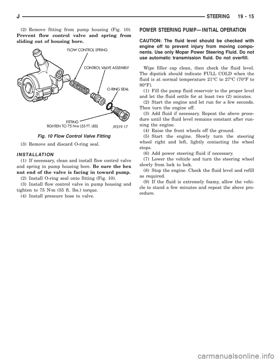
(2) Remove fitting from pump housing (Fig. 10).
Prevent flow control valve and spring from
sliding out of housing bore.
(3) Remove and discard O-ring seal.
INSTALLATION
(1) If necessary, clean and install flow control valve
and spring in pump housing bore.Be sure the hex
nut end of the valve is facing in toward pump.
(2) Install O-ring seal onto fitting (Fig. 10).
(3) Install flow control valve in pump housing and
tighten to 75 Nzm (55 ft. lbs.) torque.
(4) Install pressure hose to valve.
POWER STEERING PUMPÐINITIAL OPERATION
CAUTION: The fluid level should be checked with
engine off to prevent injury from moving compo-
nents. Use only Mopar Power Steering Fluid. Do not
use automatic transmission fluid. Do not overfill.
Wipe filler cap clean, then check the fluid level.
The dipstick should indicate FULL COLD when the
fluid is at normal temperature 21ÉC to 27ÉC (70ÉF to
80ÉF).
(1) Fill the pump fluid reservoir to the proper level
and let the fluid settle for at least two (2) minutes.
(2) Start the engine and let run for a few seconds.
Then turn the engine off.
(3) Add fluid if necessary. Repeat the above proce-
dure until the fluid level remains constant after run-
ning the engine.
(4) Raise the front wheels off the ground.
(5) Start the engine. Slowly turn the steering
wheel right and left, lightly contacting the wheel
stops.
(6) Add power steering fluid if necessary.
(7) Lower the vehicle and turn the steering wheel
slowly from lock to lock.
(8) Stop the engine. Check the fluid level and refill
as required.
(9) If the fluid is extremely foamy, allow the vehi-
cle to stand a few minutes and repeat the above pro-
cedure.
Fig. 10 Flow Control Valve Fitting
JSTEERING 19 - 15
Page 1565 of 2158
happens when the container delivery mechanism is im-
properly calibrated. Always check the lubricant level af-
ter filling to avoid an under fill condition.
A correct lubricant level check can only be made
when the vehicle is level; use a drive-on hoist to en-
sure this. Also allow the lubricant to settle for a
minute or so before checking. These recommenda-
tions will ensure an accurate check and avoid an un-
der-or-overfill condition.
HARD SHIFTING
Hard shifting is usually caused by a low lubricant
level, improper or contaminated lubricants, compo-
nent damage, incorrect clutch adjustment, or by a
damaged clutch pressure plate or disc.
Substantial lubricant leaks can result in gear, shift
rail, synchro and bearing damage. If a leak goes un-
detected for an extended period, the first indications
of a problem are usually hard shifting and noise.
Incorrect or contaminated lubricants can also con-
tribute to hard shifting. The consequence of using
non-recommended lubricants is noise, excessive wear,
internal bind and hard shifting.
Improper clutch release is a frequent cause of hard
shifting. Incorrect adjustment or a worn, damaged
pressure plate or disc can cause incorrect release. If
the clutch problem is advanced, gear clash during
shifts can result.
Worn or damaged synchro rings can cause gear clash
when shifting into any forward gear. In some new or re-
built transmissions, new synchro rings may tend to
stick slightly causing hard or noisy shifts. In most
cases, this condition will decline as the rings wear-in.
TRANSMISSION NOISE
Most manual transmissions make some noise dur-
ing normal operation. Rotating gears generate a mild
whine that is audible but only at extreme speeds.
Severe, highly audible transmission noise is gener-
ally the result of a lubricant problem. Insufficient,
improper, or contaminated lubricant will promote
rapid wear of gears, synchros, shift rails, forks and
bearings. The overheating caused by a lubricant
problem, can also lead to gear breakage.
TRANSMISSION REMOVAL
(1) Shift transmission into first or third gear. Then
raise vehicle on hoist.
(2) Support engine with adjustable jack stand. Po-
sition wood block between jack and oil pan to avoid
damaging pan.
(3) Disconnect necessary exhaust system components.
(4) Remove skid plate.
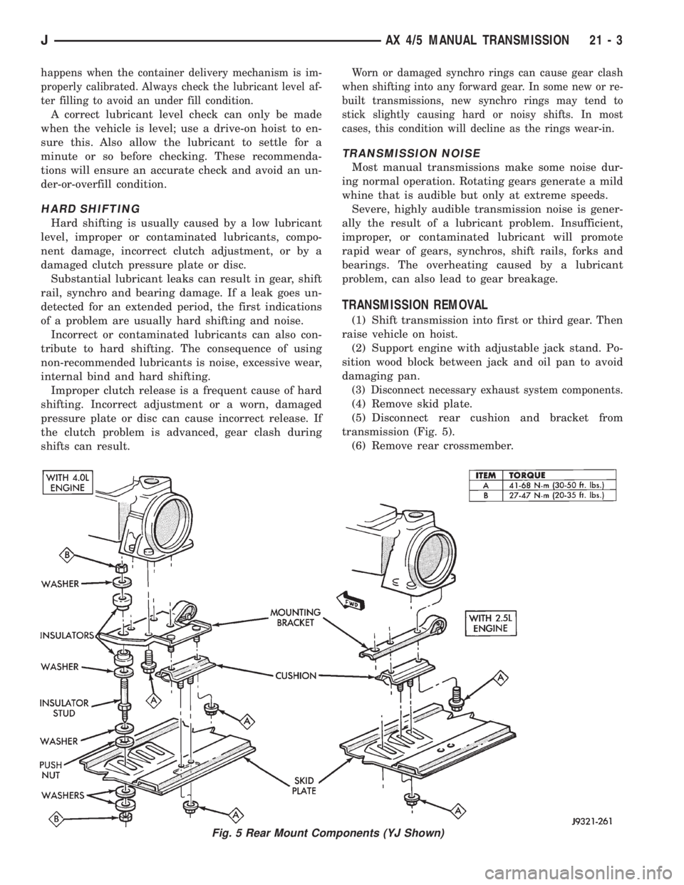
(5) Disconnect rear cushion and bracket from
transmission (Fig. 5).
(6) Remove rear crossmember.
Fig. 5 Rear Mount Components (YJ Shown)
JAX 4/5 MANUAL TRANSMISSION 21 - 3
Page 1567 of 2158
(21) Remove clutch release bearing, release fork
and retainer clip.
(22) Remove clutch housing from transmission.
TRANSMISSION INSTALLATION
(1) Install clutch housing on transmission. Tighten
housing bolts to 37 Nzm (27 ft. lbs.) torque.
(2) Lubricate contact surfaces of release fork pivot
ball stud and release fork with high temp grease.
Then install release bearing, fork and retainer clip.
(3) Mount transmission on transmission jack.
(4) Lightly lubricate pilot bearing and transmis-
sion input shaft splines with Mopar high temp
grease.
(5) Align transmission input shaft, release bearing,
and clutch disc splines. Then slide transmission into
place.
(6) Install and tighten clutch housing-to-engine
bolts to 38 Nzm (28 ft. lbs.) torque.Be sure the
housing is properly seated on engine block be-
fore tightening bolts.
(7) Lower transmission approximately 7-8 cm (3
in.) for access to shift tower. Be sure transmission is
in first or third gear.
(8) Reach up and around transmission and insert
shift lever in shift tower. Press lever retainer down-
ward and turn it clockwise to lock it in place. Then
install lever dust boot on shift tower.
(9) Install slave cylinder in clutch housing.
(10) Align and install transfer case on and trans-
mission. Tighten transfer case-to-transmission nuts
to 35 Nzm (26 ft. lbs.) torque.
(11) Connect transfer case vent hose and shift link-
age. Check and adjust linkage if necessary.
(12) Connect transfer case vent hose.
(13) Secure wire harnesses in clips/tie straps on
transmission and transfer case.
(14) Connect backup light switch wires.
(15) Connect vehicle speed sensor wires.
(16) Install and connect crankshaft position sensor.
(17) Install rear crossmember (Fig. 5). On XJ,
tighten crossmember-to-frame bolts to 41 Nzm (31 ft.
lbs.) torque. Then tighten transmission-to-rear sup-
port bolts/nuts to 45 Nzm (33 ft. lbs.) torque. On YJ,
tighten bolts/nuts to indicated torque (Fig. 5).
(18) Remove jack stand.
(19) Align and install front/rear propeller shafts.
Tighten shaft U-joint clamp bolts to 19 Nzm (170 in.
lbs.) torque.
(20) Install skid plate, if equipped. Tighten bolts to
42 Nzm (31 ft. lbs.) torque. Tighten stud nuts to 17
Nzm (150 in. lbs.) torque.
(21) Top off transmission and transfer case lubri-
cant levels.
(22) Lower vehicle.
TRANSMISSION DISASSEMBLY AND OVERHAUL
ADAPTER HOUSING AND FRONT BEARING
RETAINER REMOVAL
(1) Drain transmission lubricant.
(2) Remove release bearing and lever.
(3) Remove clutch housing bolts and remove hous-
ing.
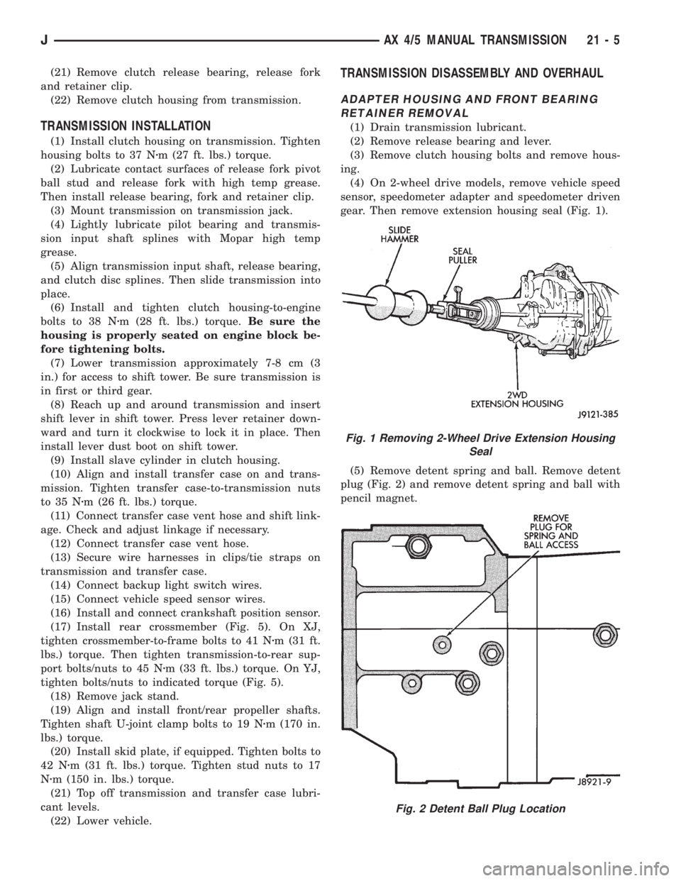
(4) On 2-wheel drive models, remove vehicle speed
sensor, speedometer adapter and speedometer driven
gear. Then remove extension housing seal (Fig. 1).
(5) Remove detent spring and ball. Remove detent
plug (Fig. 2) and remove detent spring and ball with
pencil magnet.
Fig. 1 Removing 2-Wheel Drive Extension Housing
Seal
Fig. 2 Detent Ball Plug Location
JAX 4/5 MANUAL TRANSMISSION 21 - 5
Page 1599 of 2158
(6) Install and tighten clutch housing-to-engine
bolts to 38 Nzm (28 ft. lbs.) torque.Be sure housing
is properly seated on engine before tightening
bolts.
(7) Lower transmission no more than 7.6 cm (3 in.)
for access to the shift tower.
(8) Reach up and around the transmission and in-
sert shift lever in shift tower. Press lever retainer
downward and turn it clockwise to lock it in place.
Then install lever dust boot on shift tower.
(9) Install and connect crankshaft position sensor.
(10) Align and install transfer case on transmis-
sion. Tighten transfer case attaching nuts to 35 Nzm
(26 ft. lbs.) torque.
(11) Connect transfer case vacuum and vent hoses.
(12) Install and connect transfer case shift linkage.
Check and adjust linkage if necessary.
(13) Secure wire harnesses to clips/tie straps on
transmission and transfer case.
(14) Connect backup light switch wires.
(15) Install clutch slave cylinder.
(16) Connect vehicle speed sensor wires.
(17) On XJ, install rear crossmember and attach
cushion and bracket. Tighten crossmember-to-frame
bolts to 41 Nzm (30 ft. lbs.) torque. Tighten transmis-
sion-to-rear cushion and bracket bolts/nuts to 45 Nzm
(33 ft. lbs.) torque.
(18) On YJ, install rear cushion and bracket and
skid plate. Tighten attaching bolts/nuts to indicated
torque (Fig. 1).
(19) Align and install front/rear propeller shafts.
Tighten shaft U-joint clamp bolts to 19 Nzm (170 in.
lbs.) torque.
(20) On XJ, install skid plate if removed. Tighten
bolts to 42 Nzm (31 ft. lbs.) torque. Tighten stud nuts
to 17 Nzm (150 in. lbs.) torque.
(21) Top off transmission and transfer lubricant
levels.
(22) Remove supports and lower vehicle.
TRANSMISSION DISASSEMBLY AND OVERHAUL
ADAPTER HOUSING REMOVAL
(1) Remove release bearing, release lever and re-
lease fork from clutch housing. Then remove clutch
housing from transmission.
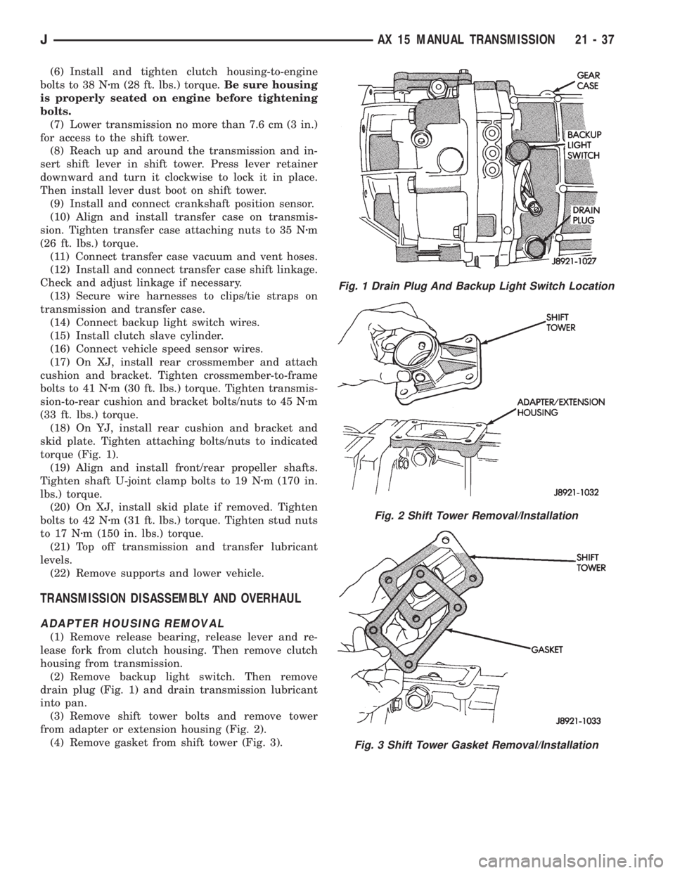
(2) Remove backup light switch. Then remove
drain plug (Fig. 1) and drain transmission lubricant
into pan.
(3) Remove shift tower bolts and remove tower
from adapter or extension housing (Fig. 2).
(4) Remove gasket from shift tower (Fig. 3).
Fig. 1 Drain Plug And Backup Light Switch Location
Fig. 2 Shift Tower Removal/Installation
Fig. 3 Shift Tower Gasket Removal/Installation
JAX 15 MANUAL TRANSMISSION 21 - 37
Page 1636 of 2158
CONVERTER STALL TEST
Stall testing involves determining maximum engine
rpm obtainable at full throttle with the rear wheels
locked and the transmission in D range. This test
checks the holding ability of the converter overrun-
ning clutch and both of the transmission clutches.
When stall testing is completed, refer to the Stall
Speed Specifications chart and Stall Speed Diagnosis
guides.
WARNING: NEVER ALLOW ANYONE TO STAND IN
FRONT OF THE VEHICLE DURING A STALL TEST.
ALWAYS BLOCK THE FRONT WHEELS AND APPLY
THE SERVICE AND PARKING BRAKES DURING
THE TEST.
STALL TEST PROCEDURE
(1) Connect tachometer to engine.
(2) Check and adjust transmission fluid level.
(3) Start and run engine until transmission fluid
reaches normal operating temperature.
(4) Block front wheels.
(5) Fully apply service and parking brakes.
(6) Open throttle completely and record maximum
engine rpm registered on tachometer. It will take
from 3 to 10 seconds to reach maximum rpm. How-
ever, once maximum rpm has been achieved,do not
hold wide open throttle for more than 5 sec-
onds.
CAUTION: Stalling the converter causes a rapid in-
crease in fluid temperature. To avoid fluid overheat-
ing, hold wide open throttle for no more than 5
seconds after reaching peak rpm. In addition, if
more than one stall test is required, run the engine
at 1000 rpm with the transmission in Neutral for at
least 20 seconds to cool the fluid.
(7) Stall speeds should be in 1700-2150 rpm range.
CAUTION: If engine exceeds 2150 rpm, release ac-
celerator pedal immediately as transmission clutch
slippage is occurring.
(8) Shift transmission into Neutral. Run engine for
20-30 seconds at 1000 rpm to cool fluid. Then stop
engine, shift transmission into Park and release
brakes.
(9) Refer to Stall Test Diagnosis.
STALL TEST DIAGNOSIS
Stall Speed Too Low
Low stall speeds with a properly tuned engine in-
dicate a torque converter overrunning clutch prob-
lem. The condition should be confirmed by road
testing prior to converter replacement.The converter overrunning clutch is slipping when
stall speeds are 250 to 350 rpm below specified min-
imum.
A converter overrunning clutch failure will result
in sluggish acceleration in all speed ranges. It will
also require greater than normal throttle opening to
maintain cruising speeds.
Stall Speed Too High
If stall speed exceeds 2150 rpm, transmission
clutch slippage is occurring.
Stall Speed Normal But Acceleration Is Sluggish
If stall speeds are within specified range but abnor-
mal throttle opening is required for acceleration, or
to maintain cruise speeds, the converter overrunning
clutch is seized. The torque converter will have to be
replaced.
Converter Noise During Test
A whining noise caused by fluid flow is normal dur-
ing a stall test. However, loud metallic noises indi-
cate a damaged converter. To confirm that noise is
originating from the converter, operate the vehicle at
light throttle in Drive and Neutral on a hoist and lis-
ten for noise from the converter housing.
AIR PRESSURE TEST
Air pressure testing can be used to check clutch
and band operation with the transmission either in
the vehicle, or on the work bench as a final check af-
ter overhaul.
Air pressure testing requires that the oil pan and
valve body be removed from the transmission.
The servo and clutch apply passages are shown in
Figure 8.
Air Test Procedure
(1) Place one or two fingers on the clutch housing
and apply air pressure through front clutch apply
passage (Fig. 8). Piston movement can be felt and a
soft thud heard as the clutch applies.
(2) Place one or two fingers on the clutch housing
and apply air pressure through rear clutch apply
passage (Fig. 8). Piston movement can be felt and a
soft thud heard as the clutch applies.
(3) Apply air pressure to the front servo apply pas-
sage. The servo rod should extend and cause the
band to tighten around the drum. Spring tension
should release the servo when air pressure is re-
moved.
(4) Apply air pressure to the rear servo apply pas-
sage. The servo rod should extend and cause the
band to tighten around the drum. Spring tension
should release the servo when air pressure is re-
moved.
21 - 74 30RH/32RH TRANSMISSION DIAGNOSISJ
Page 1675 of 2158
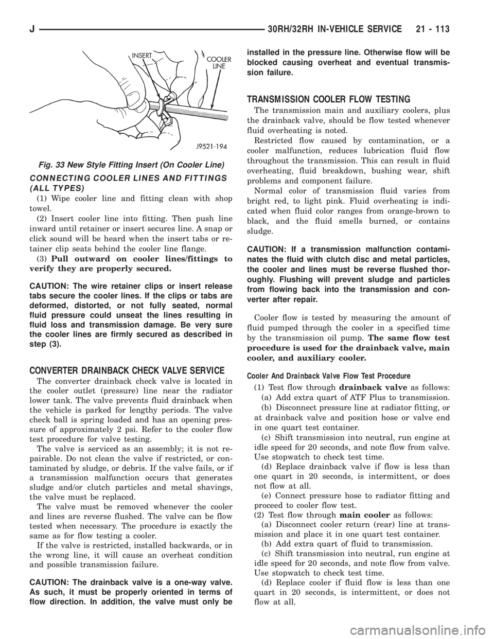
CONNECTING COOLER LINES AND FITTINGS
(ALL TYPES)
(1) Wipe cooler line and fitting clean with shop
towel.
(2) Insert cooler line into fitting. Then push line
inward until retainer or insert secures line. A snap or
click sound will be heard when the insert tabs or re-
tainer clip seats behind the cooler line flange.
(3)Pull outward on cooler lines/fittings to
verify they are properly secured.
CAUTION: The wire retainer clips or insert release
tabs secure the cooler lines. If the clips or tabs are
deformed, distorted, or not fully seated, normal
fluid pressure could unseat the lines resulting in
fluid loss and transmission damage. Be very sure
the cooler lines are firmly secured as described in
step (3).
CONVERTER DRAINBACK CHECK VALVE SERVICE
The converter drainback check valve is located in
the cooler outlet (pressure) line near the radiator
lower tank. The valve prevents fluid drainback when
the vehicle is parked for lengthy periods. The valve
check ball is spring loaded and has an opening pres-
sure of approximately 2 psi. Refer to the cooler flow
test procedure for valve testing.
The valve is serviced as an assembly; it is not re-
pairable. Do not clean the valve if restricted, or con-
taminated by sludge, or debris. If the valve fails, or if
a transmission malfunction occurs that generates
sludge and/or clutch particles and metal shavings,
the valve must be replaced.
The valve must be removed whenever the cooler
and lines are reverse flushed. The valve can be flow
tested when necessary. The procedure is exactly the
same as for flow testing a cooler.
If the valve is restricted, installed backwards, or in
the wrong line, it will cause an overheat condition
and possible transmission failure.
CAUTION: The drainback valve is a one-way valve.
As such, it must be properly oriented in terms of
flow direction. In addition, the valve must only beinstalled in the pressure line. Otherwise flow will be
blocked causing overheat and eventual transmis-
sion failure.
TRANSMISSION COOLER FLOW TESTING
The transmission main and auxiliary coolers, plus
the drainback valve, should be flow tested whenever
fluid overheating is noted.
Restricted flow caused by contamination, or a
cooler malfunction, reduces lubrication fluid flow
throughout the transmission. This can result in fluid
overheating, fluid breakdown, bushing wear, shift
problems and component failure.
Normal color of transmission fluid varies from
bright red, to light pink. Fluid overheating is indi-
cated when fluid color ranges from orange-brown to
black, and the fluid smells burned, or contains
sludge.
CAUTION: If a transmission malfunction contami-
nates the fluid with clutch disc and metal particles,
the cooler and lines must be reverse flushed thor-
oughly. Flushing will prevent sludge and particles
from flowing back into the transmission and con-
verter after repair.
Cooler flow is tested by measuring the amount of
fluid pumped through the cooler in a specified time
by the transmission oil pump.The same flow test
procedure is used for the drainback valve, main
cooler, and auxiliary cooler.
Cooler And Drainback Valve Flow Test Procedure
(1) Test flow throughdrainback valveas follows:
(a) Add extra quart of ATF Plus to transmission.
(b) Disconnect pressure line at radiator fitting, or
at drainback valve and position hose or valve end
in one quart test container.
(c) Shift transmission into neutral, run engine at
idle speed for 20 seconds, and note flow from valve.
Use stopwatch to check test time.
(d) Replace drainback valve if flow is less than
one quart in 20 seconds, is intermittent, or does
not flow at all.
(e) Connect pressure hose to radiator fitting and
proceed to cooler flow test.
(2) Test flow throughmain cooleras follows:
(a) Disconnect cooler return (rear) line at trans-
mission and place it in one quart test container.
(b) Add extra quart of fluid to transmission.
(c) Shift transmission into neutral, run engine at
idle speed for 20 seconds, and note flow from valve.
Use stopwatch to check test time.
(d) Replace cooler if fluid flow is less than one
quart in 20 seconds, is intermittent, or does not
flow at all.
Fig. 33 New Style Fitting Insert (On Cooler Line)
J30RH/32RH IN-VEHICLE SERVICE 21 - 113
Page 1732 of 2158
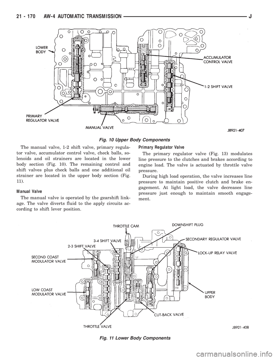
The manual valve, 1-2 shift valve, primary regula-
tor valve, accumulator control valve, check balls, so-
lenoids and oil strainers are located in the lower
body section (Fig. 10). The remaining control and
shift valves plus check balls and one additional oil
strainer are located in the upper body section (Fig.
11).
Manual Valve
The manual valve is operated by the gearshift link-
age. The valve diverts fluid to the apply circuits ac-
cording to shift lever position.Primary Regulator Valve
The primary regulator valve (Fig. 13) modulates
line pressure to the clutches and brakes according to
engine load. The valve is actuated by throttle valve
pressure.
During high load operation, the valve increases line
pressure to maintain positive clutch and brake en-
gagement. At light load, the valve decreases line
pressure just enough to maintain smooth engage-
ment.
Fig. 10 Upper Body Components
Fig. 11 Lower Body Components
21 - 170 AW-4 AUTOMATIC TRANSMISSIONJ
Page 2126 of 2158
ANTENNA........................8F-2,8F-5
ANTENNA, POWER; RADIO (XJ-RHD) . . . 8W-47-1
ANTENNA REMOVE/INSTALL - XJ.........8F-8
ANTENNA REMOVE/INSTALL - YJ........8F-10
ANTILOCK BRAKES (ABS)................5-1
ANTILOCK BRAKING MODE, ABS
OPERATION IN.......................5-36
ANTILOCK ECU AND HCU DIAGNOSIS......5-3
APPLICATION CHARTS, GEARTRAIN
OPERATION........................21-169
APPLICATION, TRANSMISSION..........21-67
APPLICATIONÐXJ VEHICLES, BULB......8L-18
APPLICATIONÐYJ VEHICLES, BULB......8L-32
APPLIQUEÐXJ, QUARTER WINDOW.....23-25
APPLIQUEÐYJ, RADIATOR GRILLE.....23-104
APRONSÐYJ, FENDER SPLASH........23-115
ARM, LOWER SUSPENSION.............2-13
ARM, PITMAN..................19-17,19-20
ARM REMOVE/INSTALL, LIFTGATE
WIPER.............................8K-17
ARM REMOVE/INSTALL, WINDSHIELD
WIPER.............................8K-17
ARM, UPPER SUSPENSION.............2-12
ARMING/DISARMING MECHANISM;
RESTRAINT SYSTEMS.................8M-2
ARMING/DISARMING MECHANISM;
STEERING..........................19-48
ARMS AND PUSH RODS, ROCKER....9-23,9-65
ASH RECEIVER TRAY LAMPÐXJ, I/P.....23-80
ASSEMBLY....................19-63,19-71
ASSEMBLY AND ADJUSTMENT, VALVE
BODY.............................21-153
ASSEMBLY, CALIPER...................5-50
ASSEMBLY, COMPRESSOR CLUTCH......24-20
ASSEMBLY, DIFFERENTIAL; FRONT
SUSPENSION AND AXLE................2-38
ASSEMBLY, DIFFERENTIAL; REAR
SUSPENSION AND AXLES...............3-21
ASSEMBLY, FINAL; FRONT SUSPENSION
AND AXLE...........................2-46
ASSEMBLY, FINAL; REAR SUSPENSION
AND AXLES..........................3-29
ASSEMBLY, FUEL RAIL................14-62
ASSEMBLY, GEAR....................19-43
ASSEMBLY, IMPACT SENSOR/INFLATOR . . . 8M-2
ASSEMBLY, PINION MEASUREMENT.......3-22
ASSEMBLY REMOVE/INSTALL, CLUSTER . . 8E-17,
8E-35
ASSEMBLY REPLACEMENT, ADJUSTER
PLUG..............................19-29
ASSEMBLY REPLACEMENT, COLUMN.....19-52
ASSEMBLY REPLACEMENTÐXJ
VEHICLES, DRIVE AXLE; FRONT
SUSPENSION AND AXLE................2-23
ASSEMBLY REPLACEMENTÐXJ
VEHICLES, DRIVE AXLE; REAR
SUSPENSION AND AXLES...........3-14,3-31
ASSEMBLY REPLACEMENTÐYJ
VEHICLES, DRIVE AXLE; FRONT
SUSPENSION AND AXLE................2-24
ASSEMBLY REPLACEMENTÐYJ
VEHICLES, DRIVE AXLE; REAR
SUSPENSION AND AXLES...............3-14
ASSEMBLY (SHORT BLOCK), SERVICE
ENGINE..............................9-4
ASSEMBLY TIPS, TRANSMISSION......21-155
ASSEMBLY, TRANSFER CASE
....21-294,21-319
ASSEMBLY/INSTALLATION, PINION GEAR
. . 2-42
ASSEMBLYÐXJ VEHICLES, ENGINE
. . . 9-18,9-59
ASSEMBLYÐYJ VEHICLES, ENGINE
. . . 9-20,9-62
ASSIST HANDLEÐXJ
.................23-89
ASSIST HANDLEÐYJ, FULL-METAL
DOOR
............................23-136
AUTO SHUTDOWN (ASD) RELAYÐPCM
OUTPUT
............................14-26
AUTOMATIC BELT TENSIONERÐXJ
MODELS WITH RIGHT HAND DRIVE
.......7-42
AUTOMATIC SHUT DOWN (ASD) RELAY;
FUEL/IGNITION (XJ)
................8W-30-1
AUTOMATIC SHUT DOWN (ASD) RELAY;
FUEL/IGNITION (YJ)
................8W-30-1
AUTOMATIC SHUT DOWN (ASD) RELAY;
FUEL/IGNITION (XJ-RHD)
............8W-30-1
AUTOMATIC SHUTDOWN (ASD) RELAY;
FUEL SYSTEM
.......................14-59
AUTOMATIC SHUTDOWN (ASD) RELAY;
IGNITION SYSTEMS
..............8D-17,8D-1AUTOMATIC SHUTDOWN (ASD) RELAY
TEST...............................8D-6
AUTOMATIC SHUTDOWN (ASD) RELAY
TESTING...........................14-46
AUTOMATIC SHUTDOWN (ASD)
SENSEÐPCM INPUT..................14-21
AUTOMATIC TRANSMISSION............0-23
AUTOMATIC TRANSMISSION, 30RH/
32RH..............................21-67
AUTOMATIC TRANSMISSION, AW-4.....21-165
AUTOMATIC TRANSMISSION SHIFTER/
IGNITION INTERLOCK MECHANISM......19-55
AUXILIARY ELECTRIC COOLING FANÐXJ
MODELS WITH 4.0L 6-CYLINDER
ENGINE.............................7-35
AW-4 ACCUMULATOR COMPONENT
IDENTIFICATION....................21-342
AW-4 AUTOMATIC TRANSMISSION......21-165
AW-4 BUSHING AND PISTON
CLEARANCE........................21-339
AW-4 CLUTCH AND BRAKE PACK
REQUIREMENTS....................21-341
AW-4 CLUTCH DISC AND PLATE
THICKNESS........................21-338
AW-4 GENERAL SPECIFICATIONS.......21-337
AW-4 IN-VEHICLE SERVICE............21-182
AW-4 OIL PUMP WEAR LIMITS........21-338
AW-4 RETAINER AND PISTON
SPECIFICATIONS....................21-340
AW-4 TORQUE SPECIFICATIONS........21-344
AW-4 TRANSMISSION DIAGNOSIS......21-176
AW-4 TRANSMISSION OVERHAUL......21-201
AW-4 TRANSMISSION REMOVAL AND
INSTALLATION......................21-198
AW-4 VALVE AND SPRING
IDENTIFICATION....................21-343
AW-4 VALVE BODY CHECK BALL
DIMENSIONS.......................21-341
AWAY, PEDAL FALLS....................5-5
AX 15 MANUAL TRANSMISSION........21-33
AX 4/5 MANUAL TRANSMISSION.........21-1
AXLE (2WD), MODEL 30 AXLE AND
TUBE...............................2-22
AXLE, 8 1/4......................3-30,3-51
AXLE ALIGNMENT, REAR...............3-10
AXLE AND TUBE AXLE (2WD), MODEL
30 .................................2-22
AXLE ASSEMBLY REPLACEMENTÐXJ
VEHICLES, DRIVE; FRONT
SUSPENSION AND AXLE................2-23
AXLE ASSEMBLY REPLACEMENTÐXJ
VEHICLES, DRIVE; REAR SUSPENSION
AND AXLES......................3-14,3-31
AXLE ASSEMBLY REPLACEMENTÐYJ
VEHICLES, DRIVE; FRONT
SUSPENSION AND AXLE................2-24
AXLE ASSEMBLY REPLACEMENTÐYJ
VEHICLES, DRIVE; REAR SUSPENSION
AND AXLES..........................3-14
AXLE BUSHING REPLACEMENT......2-12,2-34
AXLE, FRONT DRIVE....................2-3
AXLE, MODEL 30.....................2-49
AXLE, MODEL 30 FRONT...............2-49
AXLE, MODEL 35.................3-13,3-51
AXLE NOISE/VIBRATION DIAGNOSIS;
FRONT SUSPENSION AND AXLE..........2-18
AXLE NOISE/VIBRATION DIAGNOSIS;
REAR SUSPENSION AND AXLES
..........3-9
AXLE SHAFT
.........................3-16
AXLE SHAFT, HUB BEARING
.............2-25
AXLE SHAFT OIL SEAL REPLACEMENT,
INNER
..............................2-35
AXLE SHAFT SEAL AND BEARING
........3-17
AXLE SHAFT, SEAL AND BEARING
SERVICE
............................3-32
AXLE SPECIFICATIONS; FRONT
SUSPENSION AND AXLE
................2-49
AXLE SPECIFICATIONS; REAR
SUSPENSION AND AXLES
...............3-51
AXLEÐYJ VEHICLES, VACUUM
DISCONNECT
.........................2-27
AXLES
...............................3-1
AXLES, FRONT AND REAR
..............0-24
AXLE/SHIFT MOTOR DIAGNOSIS
(CONT'D), DISCONNECT
................2-30
AXLE/SHIFT MOTOR DIAGNOSIS,
DISCONNECT
.........................2-29BACKLASH AND CONTACT PATTERN
ANALYSIS; FRONT SUSPENSION AND
AXLE...............................2-45
BACKLASH AND CONTACT PATTERN
ANALYSIS; REAR SUSPENSION AND
AXLES..............................3-27
BACK-UP LAMPS; REAR LIGHTING (XJ) . 8W-51-1
BACK-UP LAMPS; REAR LIGHTING
(XJ-RHD).........................8W-51-1
BACK-UP LAMPS; REAR LIGHTING (YJ) . 8W-51-1
BACK-UP/REAR TURN SIGNAL/TAIL
LAMP BULB REPLACEMENTÐXJ........8L-12
BACK-UP/REAR TURN SIGNAL/TAIL
LAMP BULB REPLACEMENTÐYJ........8L-28
BALANCE, TIRE AND WHEEL............22-6
BALL DIMENSIONS, AW-4 VALVE BODY
CHECK............................21-341
BALL STUD REPLACEMENTÐXJ,
LIFTGATE SUPPORT ROD..............23-63
BALL STUDS, STEERING KNUCKLE.......2-32
BAR, STABILIZER; FRONT SUSPENSION
AND AXLE.......................2-11,2-15
BAR, STABILIZER; REAR SUSPENSION
AND AXLES...........................3-5
BAR, TRACK; FRONT SUSPENSION AND
AXLE...........................2-11,2-15
BAR, TRACK; REAR SUSPENSION AND
AXLES...............................3-8
BARÐXJ, SOUND....................23-94
BARÐYJ, SPORT...................23-132
BARRIERÐXJ, CARGO...............23-101
BASE COAT/CLEAR COAT FINISH.........23-158
BATTERY; BATTERY/STARTER/
GENERATOR SERVICE..................8B-1
BATTERY; BATTERY/STARTING/
CHARGING SYSTEMS DIAGNOSTICS......8A-2
BATTERY; LUBRICATION AND
MAINTENANCE.......................0-20
BATTERY CHARGING...................8A-7
BATTERY CHARGING TIME TABLE........8A-8
BATTERY CLASSIFICATIONS AND
RATINGS...........................8A-23
BATTERY DIAGNOSIS..................8A-4
BATTERY FEED; FUEL/IGNITION (XJ) . . . 8W-30-1
BATTERY FEED; FUEL/IGNITION (YJ) . . . 8W-30-2
BATTERY FEED; FUEL/IGNITION
(XJ-RHD).........................8W-30-1
BATTERY RATINGS....................8A-3
BATTERY REMOVE/INSTALL.............8B-1
BATTERY SPECIFICATIONS; BATTERY/
STARTER/GENERATOR SERVICE..........8B-8
BATTERY SPECIFICATIONS; BATTERY/
STARTING/CHARGING SYSTEMS
DIAGNOSTICS.......................8A-23
BATTERY TRAYÐXJ..................23-14
BATTERY TRAYÐYJ.................23-110
BATTERY VOLTAGEÐPCM INPUT........14-21
B/C-PILLAR AND LIFTGATE PILLAR TRIM
COVERSÐXJ........................23-88
BEARING AND AXLE SHAFT, HUB.........2-25
BEARING, AXLE SHAFT SEAL............3-17
BEARING LUBRICANTS, CHASSIS
COMPONENT AND WHEEL..............0-28
BEARING NOISE, GEAR; FRONT
SUSPENSION AND AXLE................2-18
BEARING NOISE, GEAR; REAR
SUSPENSION AND AXLES................3-9
BEARING REPLACEMENT, PILOT..........6-12
BEARING REPLACEMENT, PITMAN
SHAFT SEALS.......................19-34
BEARING REPLACEMENT, RELEASE.......6-11
BEARING SERVICE, AXLE SHAFT, SEAL....3-32
BEARINGS, CRANKSHAFT MAIN......9-45,9-87
BEARINGS, FRONT WHEEL..............0-28
BELT, ACCESSORY DRIVE...............0-21
BELT DIAGNOSIS......................7-38
BELT INDICATOR WARNING LAMP, SEAT;
INSTRUMENT CLUSTER (XJ).........8W-40-2
BELT INDICATOR WARNING LAMP, SEAT;
INSTRUMENT CLUSTER (XJ-RHD).....8W-40-2
BELT SCHEMATICS....................7-38
BELT SERVICEÐEXCEPT RIGHT HAND
DRIVE
..............................7-40
BELT SERVICEÐXJ MODELS WITH
RIGHT HAND DRIVE
...................7-42
BELT SWITCH, DRIVER'S SEAT
......8U-1,8U-3
BELT TENSION, DRIVE
.................7-45
BELT TENSION SPECIFICATIONS
..........7-38
2 INDEXJ
Description Group-Page Description Group-Page Description Group-Page