1995 JEEP XJ check engine light
[x] Cancel search: check engine lightPage 369 of 2158
Connect battery negative cable and turn ignition
switch to ON. Lamp should light. If OK, repair open
circuit to brake warning switch. If not OK, replace
bulb.
(5) Turn ignition switch to OFF and remove
jumper wire. Disconnect battery negative cable.
Check for continuity between cavity A (cavity B -
RHD) of brake warning switch connector and a good
ground with ignition switch in START position.
There should be continuity. If not OK, go to next
step.
(6) Turn ignition switch to OFF and remove
jumper wire. Disconnect battery negative cable. Un-
plug ignition switch connector. Check for continuity
between ignition switch connector cavity 3 and a
good ground. There should be no continuity. If OK, go
to next step. If not OK, repair short circuit between
ignition switch and brake warning switch connectors
as required.
(7) Check for continuity between ignition switch
connector cavity 3 and brake warning switch connec-
tor cavity A (cavity B - RHD). There should be conti-
nuity. If OK, go to next step. If not OK, repair open
circuit as required.
(8) Check for continuity between metal steering
column jacket and a good ground. There should be
continuity. If OK, go to next step. If not OK, refer to
Group 19 - Steering to check steering column ground
clip installation.
(9) Turn ignition switch to START position and
hold there. Check for continuity between terminal 3
of ignition switch and a good ground. There should
be continuity. If not OK, replace ignition switch.
(10) Unplug brake warning switch connector.
Check for continuity between parking brake switch
connector and a good ground. There should be no
continuity. If OK, go to next step. If not OK, repair
short circuit as required.
(11) Check for continuity between parking brake
switch connector and cavity B (cavity A - RHD) of
brake warning switch connector. There should be
continuity. If OK, replace parking brake switch. If
not OK, repair open circuit to brake warning switch
as required.
COOLANT TEMPERATURE WARNING LAMP
The diagnosis found here addresses an inoperative
lamp condition. If the problem being diagnosed is re-
lated to lamp accuracy, be certain to confirm that
problem is with lamp and not with cooling system
performance. Actual engine coolant temperature
should be checked with a test gauge or thermometer
before proceeding with lamp diagnosis. Refer to
Group 7 - Cooling System for more information.
(1) Turn ignition switch to START position. Lamp
should light. If OK, go to next step. If not OK, go to
step 3.(2) Turn ignition switch to ON. Disconnect coolant
temperature switch connector (Fig. 1). Jump switch
connector to ground. Lamp should light. If OK, re-
place switch. If not OK, go to next step.
(3) Turn ignition switch to OFF. Disconnect battery
negative cable. Unplug coolant temperature switch
connector. Remove instrument cluster bezel and clus-
ter assembly. Disconnect cluster connector A and
probe cavity A1. Check for continuity to a good
ground. There should be no continuity. If OK, go to
next step. If not OK, repair short circuit to coolant
temperature switch or ignition switch as required.
(4) Connect cluster connector A to cluster. Install a
jumper wire from cavity A1 of cluster connector A to
a good ground. Connect battery negative cable and
turn ignition switch to ON. Lamp should light. If OK,
repair open circuit to coolant temperature switch or
ignition switch as required. If not OK, replace bulb.
FOUR-WHEEL DRIVE INDICATOR LAMPS
(1) Apply parking brake, start engine, vehicle in
4WD Lock or 4WD.
(2) Unplug switch and touch harness side of wire
to ground. Lamp should light. If OK, check switch
operation, replace if bad. If bulb is OK, repair open
to indicator.
GENERATOR WARNING LAMP
(1) Disconnect battery negative cable and unplug
PCM connector. Install a jumper wire between cavity
36 of PCM connector (Fig. 5) and a good ground. Con-
nect battery negative cable and turn ignition switch
to ON. Lamp should light. Unplug jumper wire and
lamp should go off. If OK, refer to Powertrain Diag-
nostic Procedures to check PCM. If not OK, go to
next step.
(2) Turn ignition switch to OFF and disconnect
battery negative cable. Remove instrument cluster
bezel and cluster assembly. Install a jumper wire be-
tween cavity B8 of cluster connector A and a good
ground. Connect battery negative cable and turn ig-
nition switch to ON. Lamp should light. If OK, go to
next step. If not OK, replace bulb.
(3) Turn ignition switch to OFF and disconnect
battery negative cable. Unplug cluster connector A.
Probe cavity B8 of cluster connector A and check for
continuity to a good ground. There should be no con-
tinuity. If OK, go to next step. If not OK, repair short
circuit as required.
(4) Check for continuity between cavity B8 of clus-
ter connector A and cavity 36 of PCM connector.
There should be continuity. If not OK, repair open
circuit as required.
HEADLAMP HIGH BEAM INDICATOR LAMP
(1) Check that headlamp high beams are func-
tional. If OK, go to next step. If not OK, refer to
Group 8L - Lamps for diagnosis of headlamp system.
JINSTRUMENT PANEL AND GAUGESÐXJ 8E - 13
Page 370 of 2158
(2) Disconnect battery negative cable. Remove in-
strument cluster bezel and cluster assembly. Unplug
cluster connector A. Connect battery negative cable.
Turn headlamps on and select high beam. Check for
battery voltage at cavity A4 of cluster connector A. If
OK, replace indicator bulb. If not OK, repair circuit
to headlamp dimmer (multi-function) switch as re-
quired.
LOW FUEL WARNING LAMP
(1) Check that fuel gauge is operating as designed.
See Fuel Gauge Calibration chart in Specifications. If
OK, go to next step. If not OK, see Fuel Gauge in
this section for diagnosis.
(2) With at least 10 gallons of fuel in fuel tank, un-
plug fuel tank sending unit connector. Turn ignition
switch to ON and wait 10 seconds. Lamp (LED)
should light. Reconnect fuel tank sending unit and
wait 20 seconds. Lamp (LED) should go off. If not
OK, replace low fuel warning lamp module.
LOW OIL PRESSURE WARNING LAMP
The diagnosis found here addresses an inoperative
lamp condition. If the problem being diagnosed is re-
lated to lamp accuracy, be certain to confirm that
problem is with lamp and not with engine oiling sys-
tem. Actual engine oil pressure should be checked
with a test gauge before you proceed with lamp diag-
nosis. Refer to Group 9 - Engines for more informa-
tion.
(1) Turn ignition switch to ON. Lamp should light.
Start engine. Lamp should go off. If not OK, turn en-
gine off and go to next step.
(2) Unplug connector at oil pressure switch (Fig.
3). The switch is located on right side of engine block.
On 2.5L engine, it is just forward of ignition distrib-
utor and just to the rear of generator mounting
bracket. On 4.0L engine, it is just to the rear of igni-
tion distributor and above oil filter adapter. Install a
jumper wire from connector to a good ground. Turn
ignition switch to ON. Lamp should light. Unplug
jumper wire. Lamp should go out. If OK, replace oil
pressure switch. If not OK, go to next step.
(3) Turn ignition switch to OFF. Disconnect battery
negative cable. Remove instrument cluster bezel and
cluster assembly. Install a jumper wire from cavity
B7 (cavity B8 - RHD) of cluster connector A to a good
ground. Connect battery negative cable and turn ig-
nition switch to ON. Lamp should light. If OK, go to
next step. If not OK, replace lamp bulb.
(4) Turn ignition switch to OFF. Disconnect battery
negative cable. Unplug instrument cluster connector
A. Check continuity between cavity B7 (cavity B8 -
RHD) of cluster connector A and a good ground.
There should be no continuity. If OK, go to next step.
If not OK, repair short circuit as required.
(5) Check continuity between cavity B7 (cavity B8
- RHD) of cluster connector A and oil pressure switchconnector. There should be continuity. If not OK, re-
pair open circuit as required.
LOW WASHER FLUID WARNING LAMP
(1) Unplug washer fluid level switch connector.
Turn ignition switch to ON. Check for battery voltage
at connector cavity A. If OK, turn ignition switch to
OFF and go to next step. If not OK, repair open cir-
cuit to fuse F6 in PDC.
(2) Install a jumper wire from cavity A to cavity B
of washer fluid level switch connector. Turn ignition
switch to ON. Lamp should light. Unplug jumper and
lamp should go OFF. If OK, replace washer fluid
level switch. If not OK, go to next step.
(3) Turn ignition switch to OFF. Disconnect battery
negative cable. Remove instrument cluster bezel and
cluster assembly. Unplug instrument cluster (tell-
tale) connector B. Check continuity between cavity 16
(cavity 1 - RHD) of cluster connector B and a good
ground. There should be continuity. If OK, plug clus-
ter connector B back into cluster and go to next step.
If not OK, repair open circuit to ground as required.
(4) Connect battery negative cable. Install a
jumper wire from a 12-volt battery feed to cavity 1
(cavity 16 - RHD) of cluster connector B. Lamp
should light. If OK, go to next step. If not OK, re-
place bulb.
(5) Disconnect battery negative cable. Unplug clus-
ter connector B. Check continuity between cavity 1
(cavity 16 - RHD) of cluster connector B and a good
ground. There should be no continuity. If OK, go to
next step. If not OK, repair short circuit to switch as
required.
(6) Check continuity between cavity 1 (cavity 16 -
RHD) of cluster connector B and cavity B of washer
fluid level switch connector. There should be continu-
ity. If not OK, repair open circuit to switch as re-
quired.
MALFUNCTION INDICATOR LAMP
The diagnosis found here addresses an inoperative
lamp condition. If the lamp comes on and stays on
with engine running, refer to Group 14 - Fuel System
for diagnosis. If no fuel or emission system problem
is found, the following procedure will help locate a
short or open in the lamp circuit.
(1) Disconnect battery negative cable. Unplug PCM
connector. Install a jumper wire from cavity 32 of
PCM connector (Fig. 5) to a good ground. Connect
battery negative cable. Turn ignition switch to ON.
Lamp should light. Remove jumper wire and lamp
should go OFF. If OK, refer to Powertrain Diagnostic
Procedures to check PCM. If not OK, go to next step.
(2) Turn ignition switch to OFF. Disconnect battery
negative cable. Remove instrument cluster bezel and
cluster assembly. Install a jumper wire from cavity 2
(cavity 15 - RHD) of cluster (tell-tale) connector B to
a good ground. Connect battery negative cable. Turn
8E - 14 INSTRUMENT PANEL AND GAUGESÐXJJ
Page 382 of 2158
voltage is supplied to one side of the indicator bulb. A
ground path for the bulb is provided by 3 switches.
The bulb will light when:
²the brake warning switch is closed (indicating un-
equal brake system hydraulic pressures possibly due
to brake fluid leakage)
²the ignition switch is in the START position (bulb
test)
²the parking brake switch is closed (parking brake
is applied).
Refer to Group 5 - Brakes for more information.
FOUR-WHEEL DRIVE INDICATOR LAMP
This lamp lights when the transfer case is engaged
in the 4H or 4L position. Voltage is supplied to one
side of the indicator bulb. A switch on the front axle
disconnect housing is connected to the other side of
the indicator bulb. When the switch is closed, a path
to ground is provided and the indicator bulb lights.
HEADLAMP HIGH BEAM INDICATOR LAMP
The high beam indicator lamp is controlled by the
headlamp dimmer switch. One side of the indicator
bulb is grounded at all times. The other side of the
bulb receives battery feed through the contacts of the
dimmer switch when the turn signal switch lever is
actuated to turn the headlamp high beams on. Refer
to Group 8L - Lamps for more information.
MALFUNCTION INDICATOR LAMP
The CHECK ENGINE or Malfunction Indicator
Lamp (MIL) lights each time the ignition switch is
turned ON, and stays on for 3 seconds as a bulb test.
If the Powertrain Control Module (PCM) receives an
incorrect signal or no signal from certain fuel or
emission system related circuits or components, the
lamp is turned on. This will indicate that the PCM
has recorded a Diagnostic Trouble Code (DTC) in
electronic memory for a circuit or component mal-
function. Refer to Group 14 - Fuel System for more
information.
SEAT BELT REMINDER LAMP
The seat belt reminder lamp lights for 4 to 8 sec-
onds after the ignition switch is turned to the ON po-sition. A timer in the chime/buzzer module controls
ignition-switched battery feed to the lamp. Refer to
Group 8U - Chime/Buzzer Warning Systems for more
information.
TURN SIGNAL INDICATOR LAMPS
The left and right turn signal indicator lamps are
controlled by the turn signal and hazard warning
switches. One side of the bulb for each lamp is
grounded at all times. The other side of the bulb re-
ceives battery feed through the contacts of the turn
signal switch, when the turn signal lever or hazard
warning button are actuated. Refer to Group 8J -
Turn Signal and Hazard Warning Systems for more
information.
UPSHIFT INDICATOR LAMP
Vehicles equipped with manual transmissions have
an optional upshift indicator lamp. Ground feed for
the lamp is switched by the Powertrain Control Mod-
ule (PCM). The lamp lights to indicate when the
driver should shift to the next highest gear for best
fuel economy. The PCM will turn the lamp off after 3
to 5 seconds if the upshift is not performed. The lamp
will remain off until the vehicle stops accelerating
and is brought back to the range of lamp operation,
or until the transmission is shifted into another gear.
The indicator lamp is normally on when the igni-
tion switch is turned ON and is turned off when the
engine is started. The lamp will be turned on during
vehicle operation according to engine speed and load.
CLUSTER ILLUMINATION LAMPS
All cluster illumination lamps receive battery feed
from the instrument lamps fuse in the fuseblock
module through the panel dimmer switch. When the
park or headlamps are on, the cluster illumination
lamps light. Illumination brightness can be adjusted
by rotating the panel dimmer thumb-wheel, which is
next to the headlamp switch.
8E - 26 INSTRUMENT PANEL AND GAUGESÐYJJ
Page 389 of 2158
(9) Turn ignition switch to START position and
hold there. Check for continuity between terminal for
circuit G11 of ignition switch and a good ground.
There should be continuity. If not OK, replace igni-
tion switch.
(10) Unplug brake warning switch connector.
Check for continuity between parking brake switch
connector and a good ground. There should be no
continuity. If OK, go to next step. If not OK, repair
short circuit as required.
(11) Check for continuity between parking brake
switch connector and brake warning switch connector
cavity for circuit G11. There should be continuity. If
OK, replace parking brake switch. If not OK, repair
open circuit to brake warning switch as required.
FOUR-WHEEL DRIVE INDICATOR LAMP
(1) Apply parking brake, start engine, vehicle in
4WD Lock or 4WD.
(2) Unplug switch and touch harness side of wire
to ground. Lamp should light. If OK, check switch
operation, replace if bad. If bulb is OK, repair open
to indicator.
HEADLAMP HIGH BEAM INDICATOR LAMP
(1) Check that headlamp high beams are func-
tional. If OK, go to next step. If not OK, refer to
Group 8L - Lamps for diagnosis of headlamp system.
(2) Disconnect battery negative cable. Remove left
instrument cluster bezel and main cluster assembly.
Unplug cluster connector. Connect battery negative
cable. Turn headlamps on and select high beam.
Check for battery voltage at cavity 17 of cluster con-
nector. If OK, replace indicator bulb. If not OK, re-
pair circuit to headlamp dimmer switch as required.
MALFUNCTION INDICATOR LAMP
The diagnosis found here addresses an inoperative
lamp condition. If the lamp comes on and stays on
with engine running, refer to Group 14 - Fuel System
for diagnosis. If no fuel or emission system problem
is found, the following procedure will help locate a
short or open in the lamp circuit.
(1) Disconnect battery negative cable. Unplug PCM
connector. Install a jumper wire from cavity 32 of
PCM connector (Fig. 5) to a good ground. Connect
battery negative cable. Turn ignition switch to ON.
Lamp should light. Remove jumper wire and lamp
should go OFF. If OK, refer to Powertrain Diagnostic
Procedures to check PCM. If not OK, go to next step.
(2) Turn ignition switch to OFF. Disconnect battery
negative cable. Remove left instrument cluster bezel
and main cluster assembly. Install a jumper wire
from cavity 2 of cluster connector to a good ground.
Connect battery negative cable. Turn ignition switch
to ON. Lamp should light. If OK, go to next step. If
not OK, replace bulb.(3) Turn ignition switch to OFF. Disconnect battery
negative cable. Unplug cluster connector. Check for
continuity between cavity 2 of cluster connector and
a good ground. There should be no continuity. If OK,
go to next step. If not OK, repair short circuit to
PCM as required.
(4) Check continuity between cavity 2 of cluster
connector and cavity 32 of PCM connector. There
should be continuity. If not OK, repair open circuit to
PCM as required.
SEAT BELT REMINDER LAMP
(1) Refer to Group 8U - Chime/Buzzer Warning
Systems to check chime/buzzer module operation. If
OK, go to next step. If not OK, replace chime/buzzer
module.
(2) Disconnect battery negative cable. Remove left
instrument cluster bezel and main cluster assembly.
Unplug cluster connector. Check for continuity be-
tween cavity 20 of cluster connector and a good
ground. There should be continuity. If OK, plug clus-
ter connector back into cluster and go to next step. If
not OK, repair open circuit to ground as required.
(3) Connect battery negative cable. Install a
jumper wire between a 12-volt battery feed and cav-
ity 16 of cluster connector. Lamp should light. If OK,
go to next step. If not OK, replace bulb.
(4) Disconnect battery negative cable. Unplug
chime/buzzer module from fuseblock module. Unplug
cluster connector. Check for continuity between cav-
ity 16 of cluster connector and a good ground. There
should be no continuity. If OK, go to next step. If not
OK, repair short circuit to chime/buzzer module as
required.
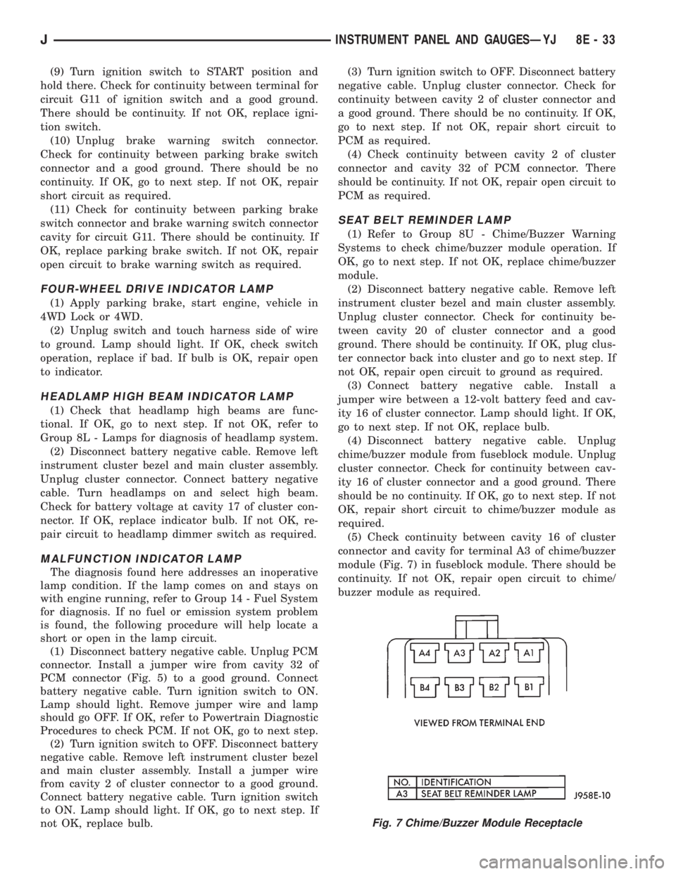
(5) Check continuity between cavity 16 of cluster
connector and cavity for terminal A3 of chime/buzzer
module (Fig. 7) in fuseblock module. There should be
continuity. If not OK, repair open circuit to chime/
buzzer module as required.
Fig. 7 Chime/Buzzer Module Receptacle
JINSTRUMENT PANEL AND GAUGESÐYJ 8E - 33
Page 430 of 2158
lamps and repair circuits or replace bulbs as re-
quired. If system still does not function properly, pro-
ceed as follows.
(1) Locate fuseblock module under driver's side of
instrument panel. Remove and inspect fuse 4. If OK,
go to next step. If not OK, replace fuse as required.
(2) Replace turn signal flasher (light blue can in
fuseblock module) with a known good unit. Test op-
eration. If OK, replace faulty turn signal flasher. If
not OK, remove test flasher and go to next step.
(3) Turn ignition switch to ACCESSORY position.
Check for battery voltage at flasher cavity on left
(closest to hazard flasher). If OK, go to next step. If
not OK, repair circuit to fuse 4 as required.
(4) Turn ignition switch to OFF position. See Turn
Signal/Hazard Warning Switch Remove/Install to lo-
cate steering column connector. Unplug connector.
(5) Turn ignition switch to ACCESSORY position.
Check for battery voltage at connector terminal L. If
OK, replace turn signal/hazard warning switch. If not
OK, repair circuit between turn signal flasher and
steering column connector.
HAZARD WARNING SYSTEM - YJ
(1) Locate Power Distribution Center (PDC) near
battery tray in engine compartment. Remove and in-
spect fuse F5. If OK, go to next step. If not OK,
replace fuse as required.(2) Replace hazard warning flasher (metal can in
fuseblock module) with a known good unit. Test op-
eration. If OK, replace faulty hazard warning flasher.
If not OK, remove test flasher and go to next step.
(3) Check for battery voltage at flasher cavity on
left (closest to hazard flasher). If OK, go to next step.
If not OK, repair circuit to fuse F5 in PDC as re-
quired.
(4) See Turn Signal/Hazard Warning Switch Re-
move/Install to locate steering column connector. Un-
plug connector.
(5) Check for battery voltage at connector terminal
K. If OK, replace turn signal/hazard warning switch.
If not OK, repair circuit between hazard warning
flasher and steering column connector.
MULTI-FUNCTION SWITCH - XJ
(1) Access multi-function switch connector and re-
move. See service procedures for Multi-Function
Switch, in this group.
(2) Using an ohmmeter, perform switch continuity
checks at the switch terminals as shown in the chart
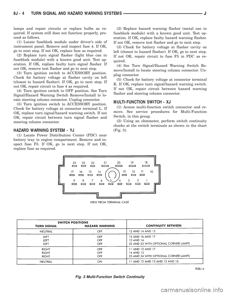
(Fig. 3).
Fig. 3 Multi-Function Switch Continuity
8J - 4 TURN SIGNAL AND HAZARD WARNING SYSTEMSJ
Page 478 of 2158
BULB APPLICATIONÐXJ VEHICLES
GENERAL INFORMATION
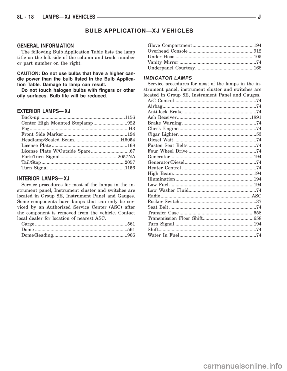
The following Bulb Application Table lists the lamp
title on the left side of the column and trade number
or part number on the right.
CAUTION: Do not use bulbs that have a higher can-
dle power than the bulb listed in the Bulb Applica-
tion Table. Damage to lamp can result.
Do not touch halogen bulbs with fingers or other
oily surfaces. Bulb life will be reduced.
EXTERIOR LAMPSÐXJ
Back-up .................................................................1156
Center High Mounted Stoplamp ..........................922
Fog ............................................................................H3
Front Side Marker .................................................194
Headlamp/Sealed Beam....................................H6054
License Plate ..........................................................168
License Plate W/Outside Spare ..............................67
Park/Turn Signal ............................................2057NA
Tail/Stop ................................................................2057
Turn Signal ...........................................................1156
INTERIOR LAMPSÐXJ
Service procedures for most of the lamps in the in-
strument panel, Instrument cluster and switches are
located in Group 8E, Instrument Panel and Gauges.
Some components have lamps that can only be ser-
viced by an Authorized Service Center (ASC) after
the component is removed from the vehicle. Contact
local dealer for location of nearest ASC.
Cargo .......................................................................561
Dome .......................................................................561
Dome/Reading.........................................................906Glove Compartment ...............................................194
Overhead Console ..................................................912
Under Hood ............................................................105
Vanity Mirror ...........................................................74
Underpanel Courtesy.............................................168
INDICATOR LAMPS
Service procedures for most of the lamps in the in-
strument panel, instrument cluster and switches are
located in Group 8E, Instrument Panel and Gauges.
A/C Control ...............................................................74
Airbag ........................................................................74
Anti-lock Brake ........................................................74
Ash Receiver .........................................................1891
Brake Warning .........................................................74
Check Engine ...........................................................74
Cigar Lighter ............................................................53
Diesel Wait ...............................................................74
Fasten Seat Belts ....................................................74
Four Wheel Drive ....................................................74
Generator ................................................................194
Generator/Diesel.......................................................74
Heater Control .........................................................74
High Beam..............................................................194
Illumination ............................................................194
Low Fuel .................................................................194
Low Washer Fluid....................................................74
Radio ......................................................................ASC
Rocker Switch...........................................................37
Seat Belt ...................................................................74
Transfer Case .........................................................658
Transmission Floor Shift.......................................658
Turn Signal.............................................................194
Shift ...........................................................................74
Water In Fuel ...........................................................74
8L - 18 LAMPSÐXJ VEHICLESJ
Page 1169 of 2158
AIR CONDITIONING AND HEATER
GENERAL INFORMATION
On vehicles built with the 2.5L engine, the electri-
cal system has provisions for dealer installed air con-
ditioning. The provisions consist of two connectors
which include circuitry for:
²Circuit C1 - Ignition feed
²Circuit C21 - Blower motor switch
²Circuit C91 - A/C request signal
²Circuit C20 - A/C select signal
²Circuit C13 - Ground for coil side of A/C compres-
sor clutch relay
²Circuit G5 - Battery voltage for coil side of A/C
compressor clutch relay
A/C COMPRESSOR
When the ignition switch is in the RUN position it
connects circuit A1 from fuse 4 in the Power Distri-
bution Center (PDC) to circuit A22. Circuit A22 sup-
plies battery voltage to fuse 12 in the fuse block.
Fuse 12 powers circuit C1.
Circuit C1 supplies battery voltage to the A/C
blower switch. Circuit C21 connects the A/C blower
switch to the A/C low pressure switch.
When the operator selects A/C operation, the A/C
blower switch provides the A/C request signal to cav-
ity 27 of the Powertrain Control Module (PCM) on
circuit C91. At the same time, the blower switch sup-
plies voltage through the A/C thermostat to circuit
C21.
Circuit C21 supplies voltage to the A/C low pres-
sure switch. When the A/C low pressure switch
closes, circuit C20 provides battery voltage to the
contact side of the A/C compressor clutch relay and
provides the A/C select signal to the PCM. Circuit
C20 is double crimped at the contact side of the re-
lay. The C20 circuit branch from the relay supplies
the A/C select input to cavity 28 of the PCM.
After receiving the A/C request signal, the PCM en-
ergizes the A/C compressor clutch relay by providing
ground for the coil side of the relay on circuit C13.
Circuit C13 connects to cavity 34 of the PCM.
Circuit G5 from fuse 9 in the fuse block supplies
voltage to the coil side of the relay. In the START or
RUN positions the ignition switch connects circuit A1
from fuse 4 in the PDC with circuit A21. Circuit A21
connects to the fuse block bus bar that powers circuit
C5 through fuse 9.
When the PCM energizes the A/C compressor
clutch relay, the relay switches from its normally
grounded position to connect circuit C20 to circuit
C3. Circuit C3 supplies voltage to the case grounded
A/C compressor clutch.
HELPFUL INFORMATION
²Circuit G5 is double crimped at the coil side of the
A/C compressor clutch relay. The G5 branch from the
relay continues to the back-up lamp switch.
²Circuit Z1 provides ground for the A/C compressor
clutch relay when the relay is in its normally
grounded position.
A/C-HEATER BLOWER MOTOR
When the ignition switch is in the RUN position it
connects circuit A1 from fuse 4 in the Power Distri-
bution Center (PDC) to circuit A22. Circuit A22 sup-
plies battery voltage to fuse 12 in the fuse block.
Fuse 12 powers circuit C1.
Circuit C1 supplies battery voltage to the A/C
blower switch. In the LOW position, the A/C blower
switch supplies voltage to the low speed brush of the
blower motor. In the MEDIUM position, the switch
supplies voltage to the medium speed bush of the
blower motor. In the HIGH position, the switch sup-
plies voltage to the high speed brush of the blower
motor.
The blower motor has a field jumper. The ground
circuit for the blower motor connects to the cigar
lighter. Circuit Z1 provides ground for the blower mo-
tor and the cigar lighter.
HELPFUL INFORMATION
²Check fuse 4 in the PDC.
²Check fuse 12 in the fuse block.
DIAGRAM INDEX
Component Page
A/C Compressor Clutch.....................8W-42-4
A/C Compressor Clutch Relay................8W-42-4
A/C Thermostat..........................8W-42-5
Blower Motor...........................8W-42-5
Blower Motor Switch......................8W-42-5
Fuse 4 (PDC).........................8W-42-4, 6
Fuse 7 (Fuse Block).......................8W-42-6
Fuse 9 (Fuse Block).....................8W-42-4, 6
Fuse 12 (Fuse Block)....................8W-42-4, 6
Ignition Switch........................8W-42-4, 6
Powertrain Control Module.................8W-42-4, 6
8W - 42 - 2 8W-42 AIR CONDITIONING/HEATERÐYJ VEHICLESJ
Page 1281 of 2158
minutes). The use of a locating dowel is recom-
mended during assembly to prevent smearing the
material off location.
Mopar Gasket Maker should be applied sparingly
to one gasket surface. The sealant diameter should
be 1.00 mm (0.04 inch) or less. Be certain the mate-
rial surrounds each mounting hole. Excess material
can easily be wiped off. Components should be
torqued in place within 15 minutes. The use of a lo-
cating dowel is recommended during assembly to pre-
vent smearing the material off location.
ENGINE PERFORMANCE
To provide best vehicle performance and lowest ve-
hicle emissions, it is most important that the tune-up
be done accurately. Use the specifications listed on
the Vehicle Emission Control Information label found
on the engine compartment hood.
(1) Test battery specific gravity. Add water, if nec-
essary. Clean and tighten battery connections.
(2) Test cranking amperage draw (refer to Group
8B, Battery/Starter Service for the proper proce-
dures).
(3) Tighten the intake manifold bolts (refer to
Group 11, Exhaust System and Intake Manifold for
the proper specifications).
(4) Perform cylinder compression test:
(a) Check engine oil level and add oil, if neces-
sary.
(b) Drive the vehicle until engine reaches normal
operating temperature.
(c) Select a route free from traffic and other
forms of congestion, observe all traffic laws and
briskly accelerate through the gears several times.
The higher engine speed may help clean out valve
seat deposits which can prevent accurate compres-
sion readings.
CAUTION: DO NOT overspeed the engine.
(d) Remove all spark plugs from engine. As spark
plugs are being removed, check electrodes for ab-
normal firing indicatorsÐfouled, hot, oily, etc.
Record cylinder number of spark plug for future
reference.
(e) Disconnect coil wire from distributor and se-
cure to good ground to prevent a spark from start-
ing a fire.
(f) Be sure throttle blades are fully open during
the compression check.
(g) Insert compression gage adaptor into the
No.1 spark plug hole. Crank engine until maximum
pressure is reached on gauge. Record this pressure
as No.1 cylinder pressure.
(h) Repeat Step 4g for all remaining cylinders.
(i) Compression should not be less than 689 kPa
(100 psi) and not vary more than 172 kPa (25 psi)
from cylinder to cylinder.(j) If cylinder(s) have abnormally low compres-
sion pressures, repeat steps 4a through 4h.
(k) If the same cylinder(s) repeat an abnormally
low reading, it could indicate the existence of a
problem in the cylinder.
The recommended compression pressures are
to be used only as a guide to diagnosing engine
problems. An engine should NOT be disassem-
bled to determine the cause of low compression
unless some malfunction is present.
(5) Clean or replace spark plugs as necessary. Ad-
just gap (refer to Group 8D, Ignition System for gap
adjustment and torque).
(6) Test resistance of spark plug cables (refer to
Group 8D, Ignition System).
(7) Inspect the primary wire. Test coil output volt-
age, primary and secondary resistance. Replace parts
as necessary (refer to Group 8D, Ignition System and
make necessary adjustment).
(8) Perform a combustion analysis.
(9) Test fuel pump for pressure (refer to Group 14,
Fuel System for the proper specifications).
(10) Inspect air filter element (refer to Group 0,
Lubrication and Maintenance for the proper proce-
dure).
(11) Inspect crankcase ventilation system (refer to
Group 0, Lubrication and Maintenance for the proper
procedure).
(12) For emission controls refer to Group 25, Emis-
sion Controls System for service procedures.
(13) Inspect and adjust accessory belt drives (refer
to Group 7, Cooling System for the proper adjust-
ments).
(14) Road test vehicle as a final test.
HONING CYLINDER BORES
Before honing, stuff plenty of clean shop towels un-
der the bores and over the crankshaft to keep abra-
sive materials from entering the crankshaft area.
(1) Used carefully, the Cylinder Bore Sizing Hone
C-823 equipped with 220 grit stones, is the best tool
for this job. In addition to deglazing, it will reduce
taper and out-of-round as well as removing light
scuffing, scoring or scratches. Usually a few strokes
will clean up a bore and maintain the required lim-
its.
CAUTION: DO NOT use rigid type hones to remove
cylinder wall glaze.
(2) Deglazing of the cylinder walls may be done if
the cylinder bore is straight and round. Use a cylin-
der surfacing hone, Honing Tool C-3501, equipped
with 280 grit stones (C-3501-3810). 20-60 strokes, de-
pending on the bore condition, will be sufficient to
provide a satisfactory surface. Using honing oil
C-3501-3880 or a light honing oil available from ma-
jor oil distributors.
9 - 2 ENGINESJ