1995 JEEP XJ towing
[x] Cancel search: towingPage 273 of 2158
VISCOUS FAN DRIVE
DESCRIPTION AND OPERATION
Also refer to the previous section on Cooling Sys-
tem Fans.
The thermal viscous fan drive (Fig. 38 or 39) is a
silicone-fluid-filled coupling used to connect the fan
blades to either the engine or the water pump shaft.
The coupling allows the fan to be driven in a normal
manner. This is done at low engine speeds while lim-
iting the top speed of the fan to a predetermined
maximum level at higher engine speeds.
A thermostatic bimetallic spring coil is located on
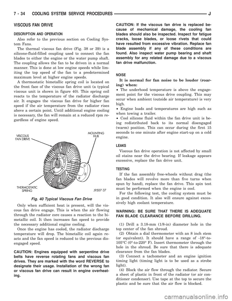
the front face of the viscous fan drive unit (a typical
viscous unit is shown in figure 40). This spring coil
reacts to the temperature of the radiator discharge
air. It engages the viscous fan drive for higher fan
speed if the air temperature from the radiator rises
above a certain point. Until additional engine cooling
is necessary, the fan will remain at a reduced rpm re-
gardless of engine speed.
Only when sufficient heat is present, will the vis-
cous fan drive engage. This is when the air flowing
through the radiator core causes a reaction to the bi-
metallic coil. It then increases fan speed to provide
the necessary additional engine cooling.
Once the engine has cooled, the radiator discharge
temperature will drop. The bimetallic coil again re-
acts and the fan speed is reduced to the previous dis-
engaged speed.
CAUTION: Engines equipped with serpentine drive
belts have reverse rotating fans and viscous fan
drives. They are marked with the word REVERSE to
designate their usage. Installation of the wrong fan
or viscous fan drive can result in engine overheat-
ing.CAUTION: If the viscous fan drive is replaced be-
cause of mechanical damage, the cooling fan
blades should also be inspected. Inspect for fatigue
cracks, loose blades, or loose rivets that could
have resulted from excessive vibration. Replace fan
blade assembly if any of these conditions are
found. Also inspect water pump bearing and shaft
assembly for any related damage due to a viscous
fan drive malfunction.
NOISE
It is normal for fan noise to be louder (roar-
ing) when:
²The underhood temperature is above the engage-
ment point for the viscous drive coupling. This may
occur when ambient (outside air temperature) is very
high.
²Engine loads and temperatures are high such as
when towing a trailer.
²Cool silicone fluid within the fan drive unit is be-
ing redistributed back to its normal disengaged
(warm) position. This can occur during the first 15
seconds to one minute after engine start-up on a cold
engine.
LEAKS
Viscous fan drive operation is not affected by small
oil stains near the drive bearing. If leakage appears
excessive, replace the fan drive unit.
TESTING
If the fan assembly free-wheels without drag (the
fan blades will revolve more than five turns when
spun by hand), replace the fan drive. This spin test
must be performed when the engine is cool.
For the following test, the cooling system must be
in good condition. It also will ensure against exces-
sively high coolant temperature.
WARNING: BE SURE THAT THERE IS ADEQUATE
FAN BLADE CLEARANCE BEFORE DRILLING.
(1) Drill a 3.18-mm (1/8-in) diameter hole in the
top center of the fan shroud.
(2) Obtain a dial thermometer with an 8 inch stem
(or equivalent). It should have a range of -18É-to-
105ÉC (0É-to-220É F). Insert thermometer through the
hole in the shroud. Be sure that there is adequate
clearance from the fan blades.
(3) Connect a tachometer and an engine ignition
timing light (timing light is to be used as a strobe
light).
(4) Block the air flow through the radiator. Secure
a sheet of plastic in front of the radiator (or air con-
ditioner condenser). Use tape at the top to secure the
plastic and be sure that the air flow is blocked.
Fig. 40 Typical Viscous Fan Drive
7 - 34 COOLING SYSTEM SERVICE PROCEDURESJ
Page 427 of 2158
TURN SIGNAL AND HAZARD WARNING SYSTEMS
CONTENTS
page page
DIAGNOSIS............................. 3
GENERAL INFORMATION.................. 1SERVICE PROCEDURES................... 5
GENERAL INFORMATION
Following are general descriptions of the major
components in the XJ (Cherokee)/YJ (Wrangler)
model turn signal and hazard warning systems. Refer
to Group 8W - Wiring Diagrams for complete circuit
descriptions and diagrams.
TURN SIGNAL SYSTEM
With the ignition switch in the ON or ACCESSORY
position and the turn signal switch lever (YJ) or
multi-function switch control lever (XJ) moved up
(right turn) or down (left turn), the turn signal sys-
tem is activated.
When the turn signal system is activated, the se-
lected (right or left) turn signal indicator lamp, front
park/turn signal lamp and rear tail/stop/turn signal
lamp bulb filaments will flash. With the headlamp
switch in the OFF position, the turn and front side
marker lamps flash in unison. With the headlamp
switch in the ON position, the turn and front side
marker lamps flash alternately.
HAZARD WARNING SYSTEM
The hazard warning is activated by a switch button
located below the ignition lock cylinder (YJ) or on the
top of the steering column (XJ) between the steering
wheel and the instrument panel. The hazard warning
flasher (YJ) or combination flasher (XJ) receives bat-
tery feed at all times, and the system is functional
regardless of ignition switch position. The hazard
warning switch button is identified with a double
triangle. On YJ models, push the switch button in to
activate the hazard warning system and pull the
button out to turn system off. On XJ models, push in
on the switch button to latch the switch and activate
the hazard warning system, and push in on the
switch button again to unlatch the switch and turn
the system off.
When the hazard warning system is activated, all
(right and left) turn signal indicator, front park/turn
signal lamp and rear tail/stop/turn signal lamp bulb
filaments will flash.
TURN SIGNAL FLASHER (YJ ONLY)
The turn signal flasher is located in the fuseblock
module. It contains one fixed contact point and one
contact point attached to a flexible bimetal arm. The
contact points are normally closed. When a turn sig-
nal is activated, current flows through the flasher. As
current flows through the bimetal arm it heats and
flexes to pull the contact points open, stopping cur-
rent flow. As the bimetal arm cools it straightens,
until the contact points close and the cycle repeats.
The standard flasher is designed to handle the cur-
rent flow requirements of the factory installed light-
ing. If supplemental lighting is added to the turn
signal circuits such as when towing a trailer with
lights, the current flow through the flasher increases.
This causes the flash rate to increase. It is recom-
mended that the standard flasher be replaced with a
heavy-duty (hazard warning) flasher when supple-
mental lighting is added.
However, when a turn signal bulb fails with a stan-
dard flasher, the remaining bulbs in that circuit will
light, but not flash. This will give the driver an indi-
cation to check the turn signal bulbs. Because a
heavy-duty flasher has different internal circuitry, a
failed bulb will not prevent the remaining bulbs in
the circuit from flashing. Therefore, it is recom-
mended that an occasional visual inspection of exte-
rior turn signal lamp operation be performed when a
heavy-duty flasher is installed.
HAZARD WARNING FLASHER (YJ ONLY)
The hazard warning flasher is located in the fuse-
block module. The hazard warning flasher contains
two normally open contact points mounted to two
flexible arms. A bimetal strip is attached between the
two arms. When the hazard warning is activated,
current flows through the flasher. As the current
flows through the bimetal strip it heats and pulls the
flexible arms together until the contact points close,
JTURN SIGNAL AND HAZARD WARNING SYSTEMS 8J - 1
Page 428 of 2158
allowing current flow to the lamps. As the bimetal
strip cools, the contact points are pushed open and
the cycle repeats.
COMBINATION FLASHER (XJ ONLY)
The combination flasher functions as both the turn
signal and hazard warning flasher on XJ models. The
combination flasher is a smart relay that is located in
the relay center under the lower instrument panel
and inboard of the steering column. The combination
flasher can not be repaired. If faulty, it must be
replaced.
The combination flasher is designed to handle the
current flow requirements of the factory installed
lighting. If supplemental lighting is added to the turn
signal circuits such as when towing a trailer with
lights, the combination flasher will automatically
compensate. This allows the flash rate to remain the
same, regardless of electrical load increases. However,
if a bulb fails in the turn signal or hazard warning
circuits, the flash rate of the remaining bulbs in that
circuit will increase to 120 flashes per minute or
higher.
TURN SIGNAL/HAZARD WARNING SWITCH
(YJ ONLY)
The turn signal and hazard warning switches are
combined into a single unit mounted within the upper
steering column bowl and beneath the steering wheel.
The turn signal lever on the left side of the steering
column is moved up or down to select the right or left
turn signal switch position. The turn signals will only
operate with the ignition switch in the ACCESSORY
or ON position.
The hazard warning button on the right side of the
steering column is pushed in to turn the hazard
warning system on, or pulled out to turn the system
off. The hazard warning system will operate regard-
less of ignition switch position. The turn signal/haz-
ard warning switch can not be repaired. If faulty, the
entire unit must be replaced.
MULTI-FUNCTION SWITCH (XJ ONLY)
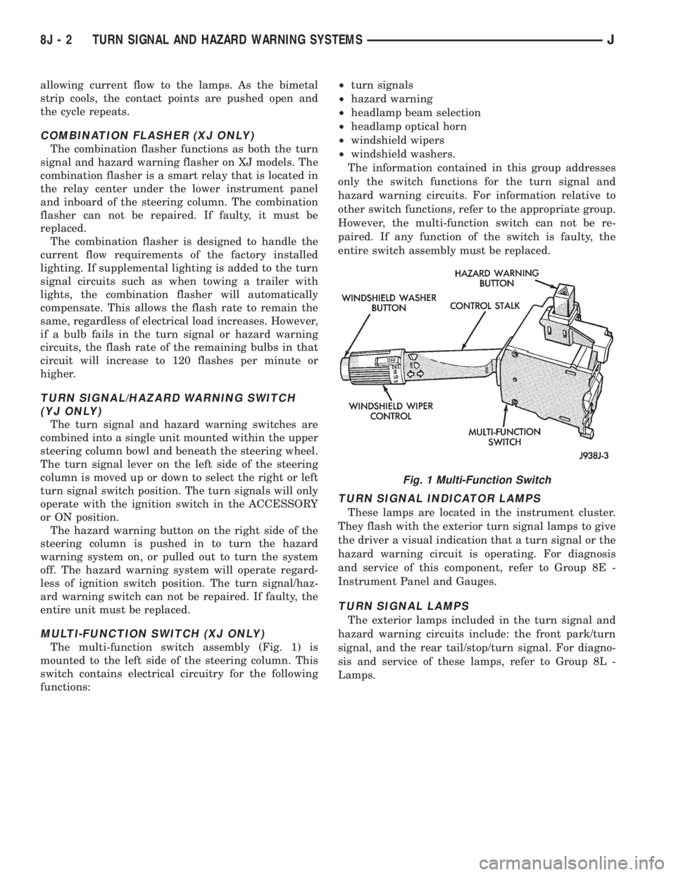
The multi-function switch assembly (Fig. 1) is
mounted to the left side of the steering column. This
switch contains electrical circuitry for the following
functions:²turn signals
²hazard warning
²headlamp beam selection
²headlamp optical horn
²windshield wipers
²windshield washers.
The information contained in this group addresses
only the switch functions for the turn signal and
hazard warning circuits. For information relative to
other switch functions, refer to the appropriate group.
However, the multi-function switch can not be re-
paired. If any function of the switch is faulty, the
entire switch assembly must be replaced.
TURN SIGNAL INDICATOR LAMPS
These lamps are located in the instrument cluster.
They flash with the exterior turn signal lamps to give
the driver a visual indication that a turn signal or the
hazard warning circuit is operating. For diagnosis
and service of this component, refer to Group 8E -
Instrument Panel and Gauges.
TURN SIGNAL LAMPS
The exterior lamps included in the turn signal and
hazard warning circuits include: the front park/turn
signal, and the rear tail/stop/turn signal. For diagno-
sis and service of these lamps, refer to Group 8L -
Lamps.
Fig. 1 Multi-Function Switch
8J - 2 TURN SIGNAL AND HAZARD WARNING SYSTEMSJ
Page 1632 of 2158
30RH/32RH TRANSMISSION DIAGNOSIS
INDEX
page page
Air Pressure Test......................... 74
Analyzing the Road Test.................... 71
Converter Housing Leak Diagnosis............ 75
Converter Stall Test........................ 74
Diagnosis Guides and Charts................ 77
Effects of Incorrect Fluid Level............... 71
Fluid Level Check......................... 70Gearshift Cable/Linkage Adjustment........... 71
General Information....................... 70
Hydraulic Pressure Test.................... 72
Preliminary Diagnosis...................... 70
Road Test............................... 71
Transmission Throttle Valve Cable Adjustment.... 71
GENERAL INFORMATION
Automatic transmission problems are generally a
result of:
²poor engine performance
²incorrect fluid level
²incorrect throttle valve cable adjustment
²incorrect band adjustment
²incorrect hydraulic control pressure adjustments
²hydraulic component malfunctions
²mechanical component malfunctions.
Begin diagnosis by checking the easily accessible
items such as fluid level, fluid condition and control
linkage adjustment. A road test will determine if fur-
ther diagnosis is necessary.
Procedures outlined in this section should be per-
formed in the following sequence to realize the most
accurate results:
²Preliminary diagnosis
²Check fluid level and condition
²Check control linkage Adjustment
²Road test
²Stall test
²Hydraulic pressure test
²Air pressure tests
²Leak test
²Analyze test results and consult diagnosis charts
PRELIMINARY DIAGNOSIS
Two basic procedures are required. One procedure
for vehicles that are driveable and an alternate pro-
cedure for disabled vehicles (will not back up or move
forward).
Vehicle Is Driveable
(1) Check fluid level and condition.
(2) Adjust throttle cable and gearshift linkage if
complaint was based on delayed, erratic, or harsh
shifts.
(3) Road test vehicle and note transmission operat-
ing characteristics.(4) Perform stall test if complaint is based on slug-
gish, low speed acceleration or abnormal throttle
opening needed to maintain normal speeds with
properly tuned engine.
(5) Perform hydraulic pressure tests.
(6) Perform air pressure test to check clutch-band
operation.
Vehicle Is Disabled
(1) Check fluid level and condition.
(2) Check for broken, disconnected throttle linkage.
(3) Check for cracked, leaking cooler lines, or loose,
missing pressure port plugs.
(4) Raise vehicle, start engine, shift transmission
into gear and note following:
(a) If propeller shafts turn but wheels do not,
problem is with differential or axle shafts.
(b) If propeller shafts do not turn and transmis-
sion is noisy, stop engine. Remove oil pan, and
check for debris. If pan is clear, remove transmis-
sion and check for damaged drive plate, converter,
oil pump or input shaft.
(c) If propeller shafts do not turn and transmis-
sion is not noisy, perform hydraulic pressure test to
determine if problem is a hydraulic or mechanical.
FLUID LEVEL CHECK
Transmission fluid level should be checked monthly
under normal operation. If the vehicle is used for
trailer towing or similar heavy load hauling, check
fluid level and condition weekly.
Fluid level is checked with the engine running at
curb idle speed, the transmission in Neutral and the
transmission fluid at normal operating temperature.
FLUID LEVEL CHECK PROCEDURE
(1) Transmission fluid must be at normal operating
temperature for accurate fluid level check. Drive ve-
hicle if necessary to bring fluid temperature up to
normal hot operating temperature of 82ÉC (180ÉF).
(2) Position vehicle on level surface. This is ex-
tremely important for accurate fluid level check.
(3) Start and run engine at curb idle speed.
21 - 70 30RH/32RH TRANSMISSION DIAGNOSISJ
Page 1661 of 2158
30RH/32RH IN-VEHICLE SERVICE
INDEX
page page
Converter Drainback Check Valve Service...... 113
Fluid and Filter Replacement................. 99
Fluid Level Check......................... 99
Front Band Adjustment.................... 102
Governor and Park Gear Service............. 105
Oil Filter Replacement..................... 103
Park Interlock Cable Adjustment (XJ).......... 101
Park Lock Component Replacement.......... 108
Park/Neutral Position Switch Service.......... 109
Rear Band Adjustment.................... 103
Recommended Fluid....................... 99Refilling After Overhaul or Fluid/Filter Change . . . 100
Shift Cable Adjustment (XJ)................. 100
Shift Linkage Adjustment (YJ)............... 100
Speedometer Service..................... 109
Throttle Valve Cable Adjustment (XJ/YJ)....... 101
Transmission Cooler Flow Testing............ 113
Transmission Cooler Line and Fitting Service.... 111
Transmission Cooler Reverse Flushing......... 114
Valve Body Installation.................... 104
Valve Body Removal...................... 104
Valve Body Service....................... 104
RECOMMENDED FLUID
Recommended (and preferred) fluid for 30RH/32RH
transmissions is Mopar ATF Plus, type 7176.
Dexron II is not really recommended and should
only be used when ATF Plus is not available.
FLUID LEVEL CHECK
Transmission fluid level should be checked monthly
under normal operation. If the vehicle is used for
trailer towing or similar heavy load hauling, check
fluid level and condition weekly.
Fluid level is checked with the engine running at
curb idle speed, the transmission in Neutral and the
transmission fluid at normal operating temperature.
FLUID LEVEL CHECK PROCEDURE
(1) Transmission fluid must be at normal operating
temperature for accurate fluid level check. Drive ve-
hicle if necessary to bring fluid temperature up to
normal hot operating temperature of 82ÉC (180ÉF).
(2) Position vehicle on level surface. This is ex-
tremely important for accurate fluid level check.
(3) Start and run engine at curb idle speed.
(4) Apply parking brakes.
(5) Shift transmission momentarily into all gear
ranges. Then shift transmission back to Neutral.
(6) Clean top of filler tube and dipstick to keep dirt
from entering tube.
(7) Remove dipstick and check fluid level as fol-
lows:
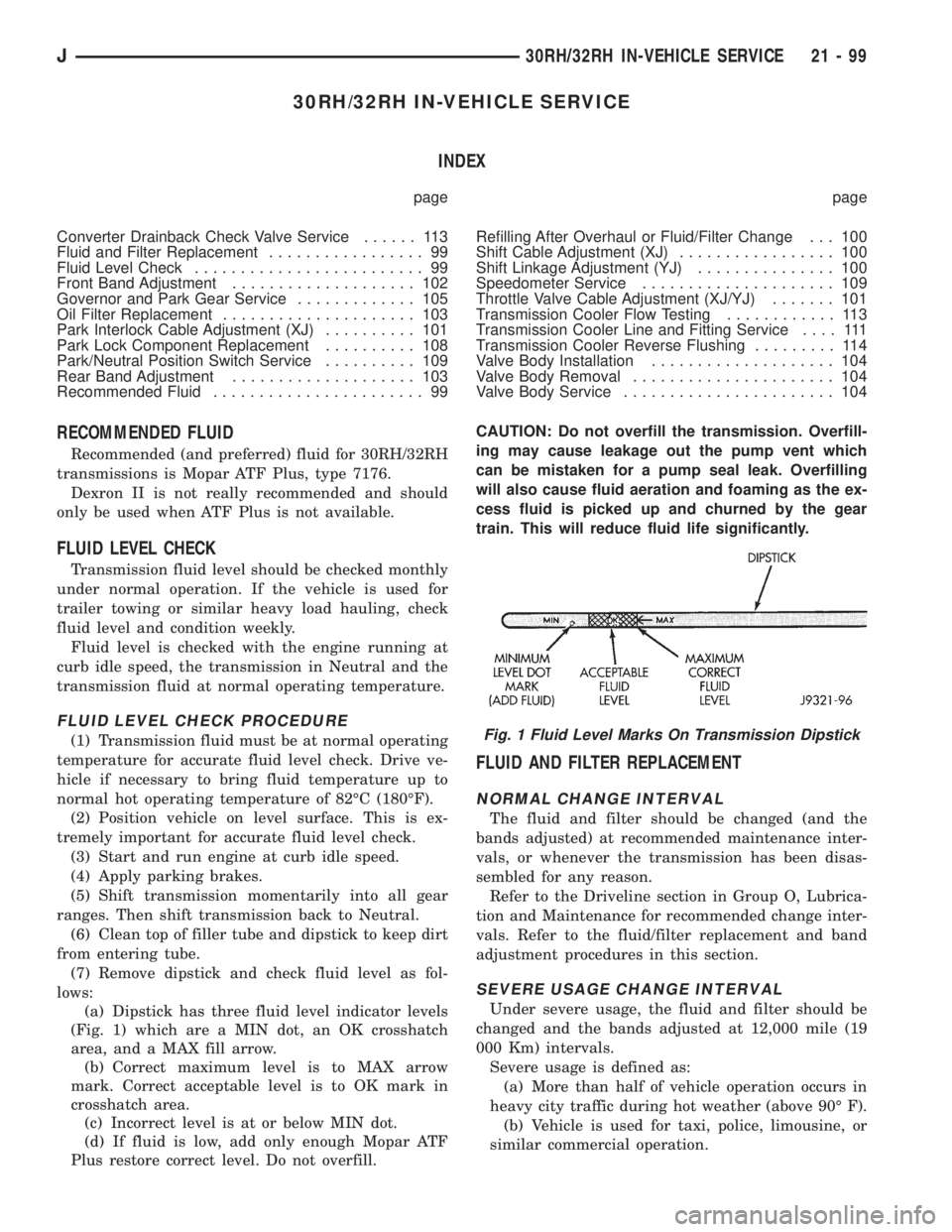
(a) Dipstick has three fluid level indicator levels
(Fig. 1) which are a MIN dot, an OK crosshatch
area, and a MAX fill arrow.
(b) Correct maximum level is to MAX arrow
mark. Correct acceptable level is to OK mark in
crosshatch area.
(c) Incorrect level is at or below MIN dot.
(d) If fluid is low, add only enough Mopar ATF
Plus restore correct level. Do not overfill.CAUTION: Do not overfill the transmission. Overfill-
ing may cause leakage out the pump vent which
can be mistaken for a pump seal leak. Overfilling
will also cause fluid aeration and foaming as the ex-
cess fluid is picked up and churned by the gear
train. This will reduce fluid life significantly.
FLUID AND FILTER REPLACEMENT
NORMAL CHANGE INTERVAL
The fluid and filter should be changed (and the
bands adjusted) at recommended maintenance inter-
vals, or whenever the transmission has been disas-
sembled for any reason.
Refer to the Driveline section in Group O, Lubrica-
tion and Maintenance for recommended change inter-
vals. Refer to the fluid/filter replacement and band
adjustment procedures in this section.
SEVERE USAGE CHANGE INTERVAL
Under severe usage, the fluid and filter should be
changed and the bands adjusted at 12,000 mile (19
000 Km) intervals.
Severe usage is defined as:
(a) More than half of vehicle operation occurs in
heavy city traffic during hot weather (above 90É F).
(b) Vehicle is used for taxi, police, limousine, or
similar commercial operation.
Fig. 1 Fluid Level Marks On Transmission Dipstick
J30RH/32RH IN-VEHICLE SERVICE 21 - 99
Page 1662 of 2158
(c) Vehicle is used for trailer towing or heavy
load hauling.
FLUID/FILTER REPLACEMENT PROCEDURE
(1) Raise vehicle.
(2) Remove oil pan and drain fluid.
(3) Clean oil pan and pan magnet. Then clean re-
maining gasket material from gasket surface of
transmission case.
(4) Remove fluid filter screws and remove filter.
(5) Position new filter on valve body and install fil-
ter screws. Tighten screws to 4 Nzm (35 in. lbs.)
torque.
(6) Adjust rear band at this time if required.
(7) Position new gasket on oil pan and install pan
on transmission. Tighten pan bolts to 150 in. lbs. (17
Nzm) torque.
(8) Adjust front band at this time if required.
(9) Lower vehicle and refill transmission with Mo-
par ATF Plus, type 7176 fluid.
REFILLING AFTER OVERHAUL OR FLUID/FILTER
CHANGE
The most effective way to avoid overfilling after a
fluid change or overhaul is as follows:
(1) Remove dipstick and insert clean funnel in
transmission fill tube.
(2) Add following initial quantity of Mopar ATF
Plus to transmission:
(a) If only fluid and filter were changed, add3
pints (1-1/2 quarts)of ATF Plus to transmission.
(b) If transmission was completely overhauled
and torque converter was replaced or drained, add
10 pints (5 quarts)of ATF Plus to transmission.
(3) Apply parking brakes.
(4) Start and run engine at normal curb idle speed.
(5) Apply service brakes, shift transmission
through all gear ranges then back to Neutral, and
leave engine running at curb idle speed.
(6) Remove funnel, insert dipstick and check fluid
level. Add only enough fluid to bring level toMIN
dot mark on dipstick.
(7) Drive vehicle until transmission fluid is at nor-
mal operating temperature. Then recheck fluid level
as described in next step.
(8) Leave engine running at curb idle speed, shift
into Neutral, and check fluid level again. This time,
add just enough fluid to bring level up toMAX ar-
row mark but do not overfill.
(9) When fluid level is correct, shut engine off, re-
lease park brake, remove funnel, and reseat dipstick
in fill tube.
SHIFT LINKAGE ADJUSTMENT (YJ)
(1) Check linkage adjustment by starting engine in
Park and Neutral.(2) Adjustment is OK if engine starts only in park
and Neutral. Adjustment is incorrect if engine starts
in one but not both positions.
(3) If engine starts in any position other than Park
or Neutral, or if engine will not start at all, park/
neutral position switch may be faulty.
(4) Shift transmission into Park.
(5) Raise vehicle.
(6) Check condition of shift rods, bellcrank,
bellcrank brackets and linkage bushings/grommets
(Fig. 2). Tighten, repair, replace worn, damaged
parts. Do not attempt adjustment if linkage compo-
nents are worn or damaged.
(7) Loosen shift rod trunnion lock bolt or nut. Be
sure upper shift rod slides freely in trunnion (Fig. 2).
Also be sure shift rods and bellcrank rotate freely
and do not bind at any point.
(8) Verify that manual lever is in Park detent (Fig.
2). Move lever all the way rearward to be sure it is in
Park.
(9) Check for positive engagement of park lock by
attempting to rotate propeller shaft. Shaft will not
turn when park pawl is engaged.
(10) Adjust shift rod trunnion to a obtain free pin
fit in bellcrank arm and tighten trunnion lock bolt or
nut. Prevent shift rod from turning while tightening
bolt or nut. Gearshift linkage lash must be elimi-
nated to obtain proper adjustment. Eliminate lash by
pulling downward on shift rod and pressing upward
on bellcrank.
(11) Confirm proper adjustment by starting engine
in Park and Neutral. Engine should start in these
positions only.If engine starts in any position
other than Park or Neutral, adjustment is in-
correct or neutral switch is faulty.
(12) Lower vehicle and verify that steering lock op-
erates correctly.
SHIFT CABLE ADJUSTMENT (XJ)
(1) Shift transmission into Park.
(2) Raise vehicle.
(3) Release cable adjuster clamp to unlock cable
(Figs. 3 and 4). Clamp is at transmission end of ca-
ble.
(4) Unsnap cable from transmission cable bracket.
(5) Move transmission shift lever fully rearward to
Park detent. Lever is on manual valve shaft at driver
side of case.
(6) Verify positive engagement of park lock by at-
tempting to rotate propeller shaft. Shaft will not ro-
tate when park lock is engaged.
(7) Snap cable into cable bracket.
(8) Lock shift cable by pressing cable adjuster
clamp down until it snaps into place.
(9) Check engine starting. Engine should start only
in Park and Neutral.
(10) Lower vehicle.
21 - 100 30RH/32RH IN-VEHICLE SERVICEJ
Page 1995 of 2158
TRAILER HITCH
TRAILER HITCHÐXJ
CLASS III HITCH
A class III weight-distributing/equalizer type hitch
can be used to tow a trailer:
²Having a maximum gross weight of 5,000 lbs/2250
kg.
²Having a maximum tongue weight of 750 lbs/332
kg).
The following vehicle basic equipment is required
for class III trailer towing:
²P205/75R15 or larger tires.
²Full size spare tire.
²Trailer sway control.
²Trailer tow wire harness and connector.
²Heavy duty turn signal flasher element.
²Heavy duty axle (with synthetic lubricant).
²Heavy duty cooling system.
²Heavy duty generator/battery.
²Auxiliary automatic transmission fluid cooler.
²I-6, 4.0L engine.
Wide-angle type door mirrors are recommended but
not required.
WIRE HARNESS CONNECTORS
CLASS I HITCH CONNECTOR
The trailer tow wire harness connector for class I
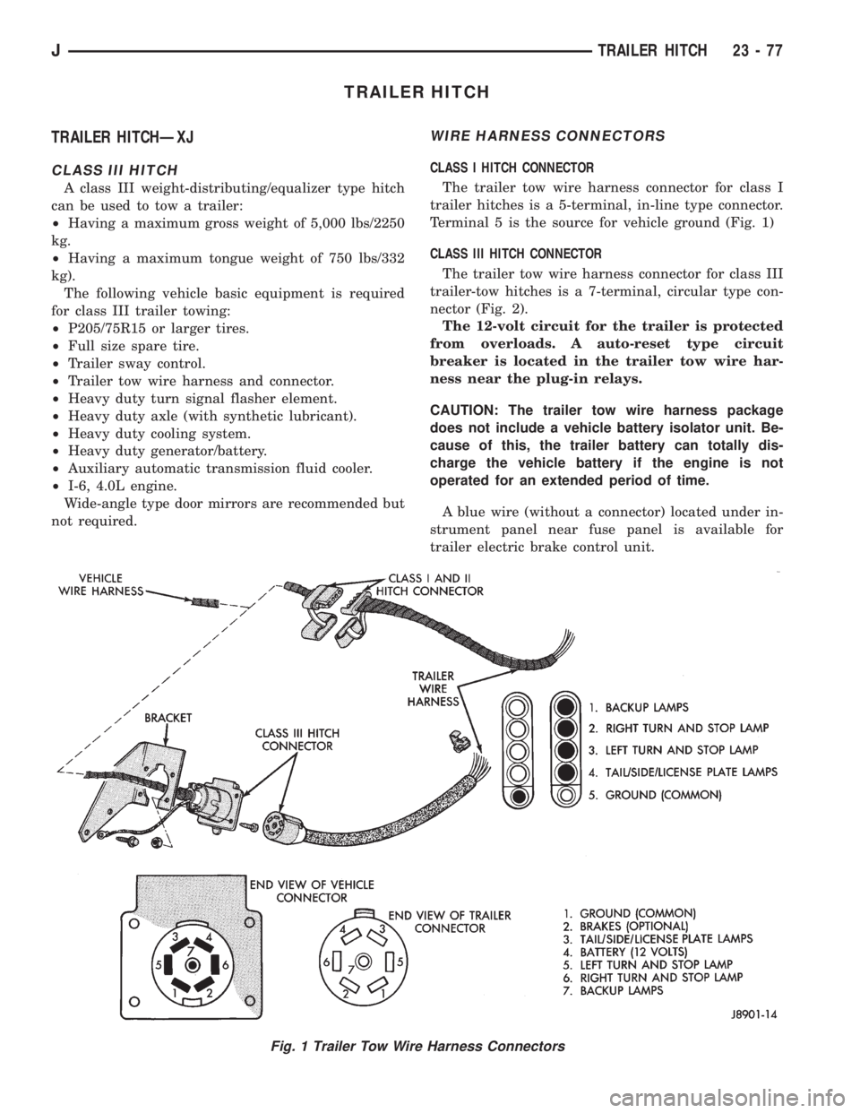
trailer hitches is a 5-terminal, in-line type connector.
Terminal 5 is the source for vehicle ground (Fig. 1)
CLASS III HITCH CONNECTOR
The trailer tow wire harness connector for class III
trailer-tow hitches is a 7-terminal, circular type con-
nector (Fig. 2).
The 12-volt circuit for the trailer is protected
from overloads. A auto-reset type circuit
breaker is located in the trailer tow wire har-
ness near the plug-in relays.
CAUTION: The trailer tow wire harness package
does not include a vehicle battery isolator unit. Be-
cause of this, the trailer battery can totally dis-
charge the vehicle battery if the engine is not
operated for an extended period of time.
A blue wire (without a connector) located under in-
strument panel near fuse panel is available for
trailer electric brake control unit.
Fig. 1 Trailer Tow Wire Harness Connectors
JTRAILER HITCH 23 - 77
Page 1996 of 2158
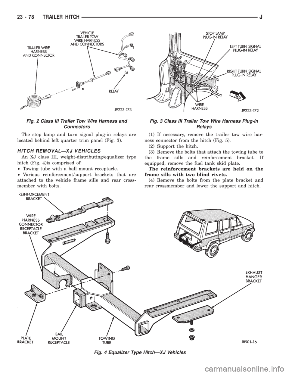
The stop lamp and turn signal plug-in relays are
located behind left quarter trim panel (Fig. 3).
HITCH REMOVALÐXJ VEHICLES
An XJ class III, weight-distributing/equalizer type
hitch (Fig. 4)is comprised of:
²Towing tube with a ball mount receptacle.
²Various reinforcement/support brackets that are
attached to the vehicle frame sills and rear cross-
member with bolts.(1) If necessary, remove the trailer tow wire har-
ness connector from the hitch (Fig. 5).
(2) Support the hitch.
(3) Remove the bolts that attach the towing tube to
the frame sills and reinforcement bracket. If
equipped, remove the fuel tank skid plate.
The reinforcement brackets are held on the
frame sills with two blind rivets.
(4) Remove the bolts from the plate bracket and
rear crossmember and lower the support and hitch.
Fig. 4 Equalizer Type HitchÐXJ Vehicles
Fig. 2 Class III Trailer Tow Wire Harness and
ConnectorsFig. 3 Class III Trailer Tow Wire Harness Plug-In
Relays
23 - 78 TRAILER HITCHJ