1995 JEEP XJ heater
[x] Cancel search: heaterPage 357 of 2158
INSTRUMENT PANEL AND GAUGES
GROUP INDEX
INSTRUMENT PANEL AND GAUGESÐXJ...... 1INSTRUMENT PANEL AND GAUGESÐYJ..... 24
INSTRUMENT PANEL AND GAUGESÐXJ
CONTENTS
page page
DIAGNOSIS............................. 5
GENERAL INFORMATION.................. 1SERVICE PROCEDURES.................. 17
SPECIFICATIONS........................ 23
GENERAL INFORMATION
Following are general descriptions of major instru-
ment panel components. Refer to Group 8W - Wiring
Diagrams for complete circuit descriptions and dia-
grams.
INSTRUMENT PANEL
Modular instrument panel construction allows all
gauges and controls to be serviced from the front of
the panel. In addition, most instrument panel wiring
or heater and air conditioning components can be ac-
cessed without complete instrument panel removal. If
necessary, the instrument panel can be rolled-down
and removed from the vehicle as an assembly.
Removal of the instrument cluster bezel allows ac-
cess to the cluster assembly, most switches, the cli-
mate controls, and the radio. Removal of the cluster
assembly allows access to the individual gauges, illu-
mination and indicator lamp bulbs, printed circuits,
and most wiring.
Removal of the lower instrument panel allows ac-
cess to heater and air conditioning components, the
fuseblock module, the relay center, and other wiring
and electrical components. Those models equipped
with a driver's-side airbag restraint have a knee
blocker and reinforcement behind the driver's-side
lower instrument panel.
The instrument panel layout is mirror image for
left-hand and right-hand drive vehicles. In most
cases, the diagnosis and service procedures found in
this group are applicable to either vehicle. Although,most illustrations represent only the typical left-hand
drive version. Exceptions are clearly identified as
Right-Hand Drive (RHD).
INSTRUMENT CLUSTERS
Two basic instrument cluster options are offered on
XJ (Cherokee) models. One is referred to as a low-
line cluster, and the other is referred to as a high-
line cluster. Each cluster is divided into two areas:
the gauge area, and the tell-tale area. Each area is
served by a separate printed circuit and wiring con-
nector. Some variations of each cluster exist due to
optional equipment and regulatory requirements.
The low-line cluster includes the following gauges:
²fuel gauge
²speedometer/odometer.
The low-line cluster includes provisions for the fol-
lowing indicator lamps:
²anti-lock brake system lamp
²brake warning lamp
²coolant temperature warning lamp
²four-wheel drive indicator lamps
²generator warning lamp
²headlamp high beam indicator lamp
²low oil pressure warning lamp
²low washer fluid warning lamp
²malfunction indicator (Check Engine) lamp
²seat belt reminder lamp
²turn signal indicator lamps
²upshift indicator lamp.
JINSTRUMENT PANEL AND GAUGES 8E - 1
Page 380 of 2158
INSTRUMENT PANEL AND GAUGESÐYJ
CONTENTS
page page
INSTRUMENT PANEL AND GAUGESÐYJ..... 22
DIAGNOSIS............................ 23
GENERAL INFORMATION................. 20SERVICE PROCEDURES.................. 31
SPECIFICATIONS........................ 39
GENERAL INFORMATION
Following are general descriptions of major instru-
ment panel components. Refer to Group 8W - Wiring
Diagrams for complete circuit descriptions and dia-
grams.
INSTRUMENT PANEL
Modular instrument panel construction allows all
gauges and controls to be serviced from the front of
the panel. In addition, most instrument panel wiring
and heater components can be accessed without com-
plete instrument panel removal.
Removal of the left instrument cluster bezel allows
access to the main cluster assembly and most
switches. Removal of the center cluster bezel allows
access to the gauge package cluster assembly, the
heater controls, and the radio. Removal of the cluster
assemblies allows access to the individual gauges, il-
lumination and indicator lamp bulbs, printed cir-
cuits, and most wiring.
INSTRUMENT CLUSTERS
The instrument cluster used on YJ (Wrangler) mod-
els consists of two separate assemblies. The main
cluster assembly is located on the left side of the in-
strument panel, centered over the steering column
opening. The gauge package cluster assembly is lo-
cated near the center of the instrument panel. Each
cluster assembly is served by a separate printed cir-
cuit and wiring connector. Some variations of each
cluster exist due to optional equipment and regula-
tory requirements.
The main cluster assembly includes a speedometer/
odometer/trip odometer and a tachometer. It also in-
cludes provisions for the following indicator lamps:
²anti-lock brake system lamp
²brake warning lamp
²headlamp high beam indicator lamp
²malfunction indicator (Check Engine) lamp
²seat belt reminder lamp²turn signal indicator lamps
²upshift indicator lamp.
The gauge package cluster assembly includes a
four-wheel drive indicator lamp and the following
gauges:
²coolant temperature gauge
²fuel gauge
²oil pressure gauge
²voltmeter.
GAUGES
With the ignition switch in the ON or START posi-
tion, voltage is supplied to all gauges through the
two cluster printed circuits. With the ignition switch
in the OFF position, voltage is not supplied to the
gauges. A gauge pointer may remain within the
gauge scale after the ignition switch is OFF. How-
ever, the gauges do not accurately indicate any vehi-
cle condition unless the ignition switch is ON.
All gauges except the odometer are air core mag-
netic units. Two fixed electromagnetic coils are lo-
cated within the gauge. These coils are wrapped at
right angles to each other around a movable perma-
nent magnet. The movable magnet is suspended
within the coils on one end of a shaft. The gauge nee-
dle is attached to the other end of the shaft.
One of the coils has a fixed current flowing through
it to maintain a constant magnetic field strength.
Current flow through the second coil changes, which
causes changes in its magnetic field strength. The
current flowing through the second coil can be
changed by:
²a variable resistor-type sending unit (fuel level,
coolant temperature, or oil pressure)
²changes in electrical system voltage (voltmeter)
²electronic control circuitry (speedometer/odometer,
tachometer).
8E - 24 INSTRUMENT PANEL AND GAUGESÐYJJ
Page 478 of 2158
BULB APPLICATIONÐXJ VEHICLES
GENERAL INFORMATION
The following Bulb Application Table lists the lamp
title on the left side of the column and trade number
or part number on the right.
CAUTION: Do not use bulbs that have a higher can-
dle power than the bulb listed in the Bulb Applica-
tion Table. Damage to lamp can result.
Do not touch halogen bulbs with fingers or other
oily surfaces. Bulb life will be reduced.
EXTERIOR LAMPSÐXJ
Back-up .................................................................1156
Center High Mounted Stoplamp ..........................922
Fog ............................................................................H3
Front Side Marker .................................................194
Headlamp/Sealed Beam....................................H6054
License Plate ..........................................................168
License Plate W/Outside Spare ..............................67
Park/Turn Signal ............................................2057NA
Tail/Stop ................................................................2057
Turn Signal ...........................................................1156
INTERIOR LAMPSÐXJ
Service procedures for most of the lamps in the in-
strument panel, Instrument cluster and switches are
located in Group 8E, Instrument Panel and Gauges.
Some components have lamps that can only be ser-
viced by an Authorized Service Center (ASC) after
the component is removed from the vehicle. Contact
local dealer for location of nearest ASC.
Cargo .......................................................................561
Dome .......................................................................561
Dome/Reading.........................................................906Glove Compartment ...............................................194
Overhead Console ..................................................912
Under Hood ............................................................105
Vanity Mirror ...........................................................74
Underpanel Courtesy.............................................168
INDICATOR LAMPS
Service procedures for most of the lamps in the in-
strument panel, instrument cluster and switches are
located in Group 8E, Instrument Panel and Gauges.
A/C Control ...............................................................74
Airbag ........................................................................74
Anti-lock Brake ........................................................74
Ash Receiver .........................................................1891
Brake Warning .........................................................74
Check Engine ...........................................................74
Cigar Lighter ............................................................53
Diesel Wait ...............................................................74
Fasten Seat Belts ....................................................74
Four Wheel Drive ....................................................74
Generator ................................................................194
Generator/Diesel.......................................................74
Heater Control .........................................................74
High Beam..............................................................194
Illumination ............................................................194
Low Fuel .................................................................194
Low Washer Fluid....................................................74
Radio ......................................................................ASC
Rocker Switch...........................................................37
Seat Belt ...................................................................74
Transfer Case .........................................................658
Transmission Floor Shift.......................................658
Turn Signal.............................................................194
Shift ...........................................................................74
Water In Fuel ...........................................................74
8L - 18 LAMPSÐXJ VEHICLESJ
Page 492 of 2158
BULB APPLICATIONÐYJ VEHICLES
GENERAL INFORMATION
The following Bulb Application Table lists the lamp
title on the left side of the column and trade number
or part number on the right.
CAUTION: Do not use bulbs that have a higher can-
dle power than the bulb listed in the Bulb Applica-
tion Table. Damage to lamp can result.
Do not touch halogen bulbs with fingers or other
oily surfaces. Bulb life will be reduced.
EXTERIOR LAMPSÐYJ
Back-up .................................................................1156
Center High Mounted Stoplamp ..........................912
Fog ............................................................................H3
Front Side Marker .................................................194
Headlamp/Sealed Beam....................................H6054
Park/Turn Signal..................................................3157
Tail/Stop ................................................................1157
INTERIOR LAMPSÐYJ
Service procedures for most of the lamps in the in-
strument panel, Instrument cluster and switches are
located in Group 8E, Instrument Panel and Gauges.
Some components have lamps that can only be ser-
viced by an Authorized Service Center (ASC) after
the component is removed from the vehicle. Contact
local dealer for location of nearest ASC.Dome/Cargo .........................................................212-2
Glove Compartment ...............................................194
Under Hood ............................................................105
Underpanel Courtesy...............................................89
INDICATOR LAMPS
Service procedures for most of the lamps in the in-
strument panel, instrument cluster and switches are
located in Group 8E, Instrument Panel and Gauges.
A/C Control ...............................................................74
Anti-lock Brake ........................................................74
Ash Receiver .........................................................1891
Brake Warning .........................................................74
Cigar Lighter ............................................................53
Fasten Seat Belts ....................................................74
Four Wheel Drive ....................................................74
Generator ................................................................194
Hazard.......................................................................74
Heater Control .......................................................194
High Beam..............................................................194
Illumination ............................................................194
Low Coolant..............................................................74
Radio ......................................................................ASC
Rocker Switch...........................................................74
Seat Belt ...................................................................74
Shift ...........................................................................74
Turn Signal.............................................................194
8L - 32 LAMPSÐYJ VEHICLESJ
Page 495 of 2158
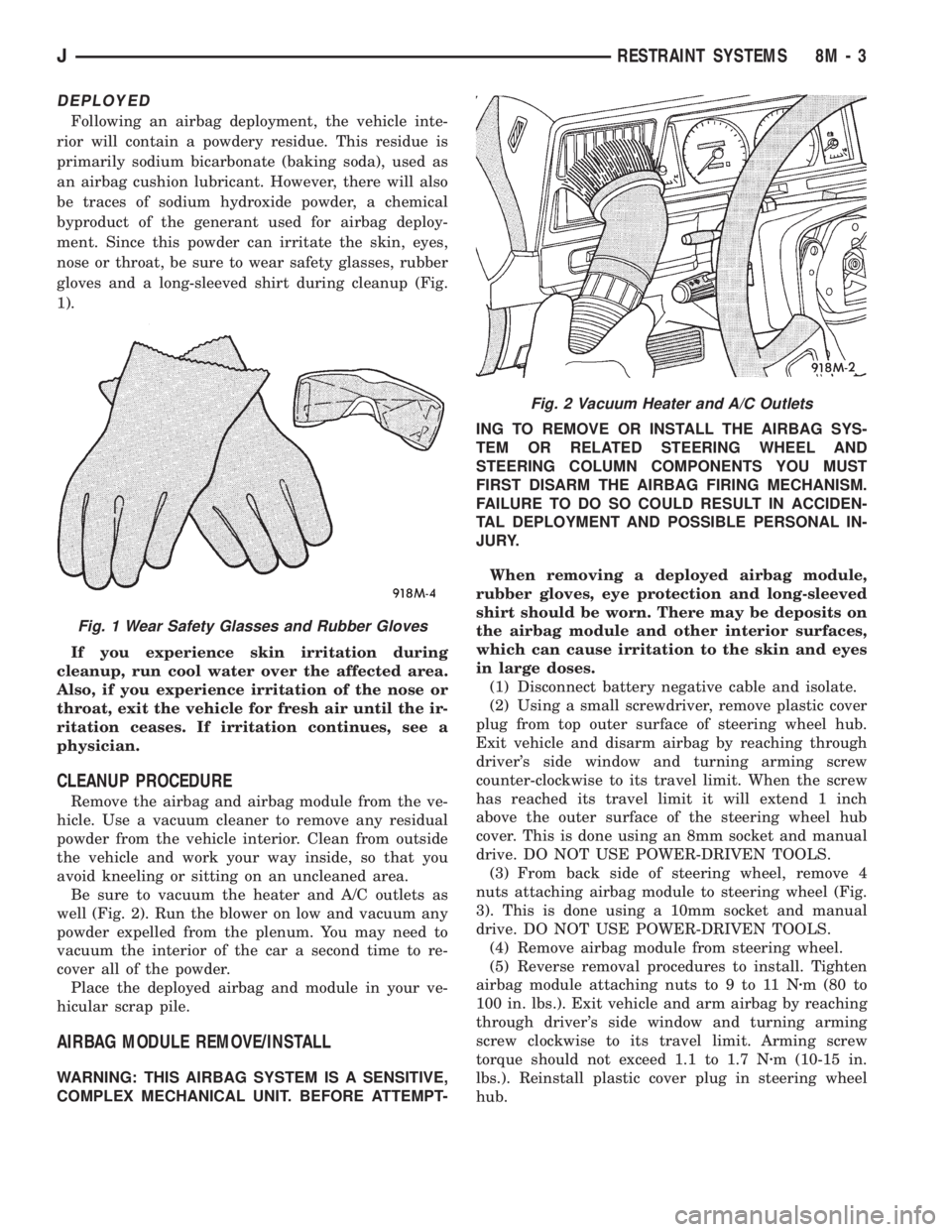
DEPLOYED
Following an airbag deployment, the vehicle inte-
rior will contain a powdery residue. This residue is
primarily sodium bicarbonate (baking soda), used as
an airbag cushion lubricant. However, there will also
be traces of sodium hydroxide powder, a chemical
byproduct of the generant used for airbag deploy-
ment. Since this powder can irritate the skin, eyes,
nose or throat, be sure to wear safety glasses, rubber
gloves and a long-sleeved shirt during cleanup (Fig.
1).
If you experience skin irritation during
cleanup, run cool water over the affected area.
Also, if you experience irritation of the nose or
throat, exit the vehicle for fresh air until the ir-
ritation ceases. If irritation continues, see a
physician.
CLEANUP PROCEDURE
Remove the airbag and airbag module from the ve-
hicle. Use a vacuum cleaner to remove any residual
powder from the vehicle interior. Clean from outside
the vehicle and work your way inside, so that you
avoid kneeling or sitting on an uncleaned area.
Be sure to vacuum the heater and A/C outlets as
well (Fig. 2). Run the blower on low and vacuum any
powder expelled from the plenum. You may need to
vacuum the interior of the car a second time to re-
cover all of the powder.
Place the deployed airbag and module in your ve-
hicular scrap pile.
AIRBAG MODULE REMOVE/INSTALL
WARNING: THIS AIRBAG SYSTEM IS A SENSITIVE,
COMPLEX MECHANICAL UNIT. BEFORE ATTEMPT-ING TO REMOVE OR INSTALL THE AIRBAG SYS-
TEM OR RELATED STEERING WHEEL AND
STEERING COLUMN COMPONENTS YOU MUST
FIRST DISARM THE AIRBAG FIRING MECHANISM.
FAILURE TO DO SO COULD RESULT IN ACCIDEN-
TAL DEPLOYMENT AND POSSIBLE PERSONAL IN-
JURY.
When removing a deployed airbag module,
rubber gloves, eye protection and long-sleeved
shirt should be worn. There may be deposits on
the airbag module and other interior surfaces,
which can cause irritation to the skin and eyes
in large doses.
(1) Disconnect battery negative cable and isolate.
(2) Using a small screwdriver, remove plastic cover
plug from top outer surface of steering wheel hub.
Exit vehicle and disarm airbag by reaching through
driver's side window and turning arming screw
counter-clockwise to its travel limit. When the screw
has reached its travel limit it will extend 1 inch
above the outer surface of the steering wheel hub
cover. This is done using an 8mm socket and manual
drive. DO NOT USE POWER-DRIVEN TOOLS.
(3) From back side of steering wheel, remove 4
nuts attaching airbag module to steering wheel (Fig.
3). This is done using a 10mm socket and manual
drive. DO NOT USE POWER-DRIVEN TOOLS.
(4) Remove airbag module from steering wheel.
(5) Reverse removal procedures to install. Tighten
airbag module attaching nuts to 9 to 11 Nzm (80 to
100 in. lbs.). Exit vehicle and arm airbag by reaching
through driver's side window and turning arming
screw clockwise to its travel limit. Arming screw
torque should not exceed 1.1 to 1.7 Nzm (10-15 in.
lbs.). Reinstall plastic cover plug in steering wheel
hub.
Fig. 1 Wear Safety Glasses and Rubber Gloves
Fig. 2 Vacuum Heater and A/C Outlets
JRESTRAINT SYSTEMS 8M - 3
Page 543 of 2158
WIRING DIAGRAMS
CONTENTS
page page
8W-01 GENERAL INFORMATIONÐWIRING
DIAGRAMS.................... 8W-01-1
8W-10 FUSE/FUSE BLOCK........... 8W-10-1
8W-11 POWER DISTRIBUTION........ 8W-11-1
8W-15 GROUND DISTRIBUTION....... 8W-15-1
8W-20 CHARGING SYSTEM.......... 8W-20-1
8W-21 STARTING SYSTEM........... 8W-21-1
8W-30 FUEL/IGNITION.............. 8W-30-1
8W-31 TRANSMISSION CONTROLS.... 8W-31-1
8W-32 ANTI-LOCK BRAKES.......... 8W-32-1
8W-33 VEHICLE SPEED CONTROL..... 8W-33-1
8W-40 INSTRUMENT CLUSTER....... 8W-40-1
8W-41 HORN/CIGAR LIGHTER......... 8W-41-1
8W-42 AIR CONDITIONING/HEATER.... 8W-42-1
8W-44 INTERIOR LIGHTING.......... 8W-44-1
8W-47 AUDIO SYSTEM.............. 8W-47-18W-48 HEATED REAR WINDOW....... 8W-48-1
8W-49 OVERHEAD CONSOLE......... 8W-49-1
8W-50 FRONT LIGHTING............. 8W-50-1
8W-51 REAR LIGHTING............. 8W-51-1
8W-52 TURN SIGNALS.............. 8W-52-1
8W-53 WIPERS..................... 8W-53-1
8W-54 TRAILER TOW................ 8W-54-1
8W-60 POWER WINDOWS.......... 8W-60-1
8W-61 POWER DOOR LOCKS......... 8W-61-1
8W-62 POWER MIRRORS............ 8W-62-1
8W-63 POWER SEAT................ 8W-63-1
8W-70 SPLICE INFORMATION........ 8W-70-1
8W-80 CONNECTOR PIN OUTS....... 8W-80-1
8W-90 CONNECTOR LOCATIONS...... 8W-90-1
8W-95 SPLICE LOCATIONS........... 8W-95-1
HOW TO USE THIS GROUP
The purpose of this group is to show the electrical
circuits in a clear, simple fashion and to make trou-
bleshooting easier. Components that work together
are shown together. All electrical components used in
a specific system are shown on one diagram. The feed
for a system is shown at the top of the page. All
wires, connectors, splices, and components are shown
in the flow of current to the bottom of the page. Wir-
ing which is not part of the circuit represented is ref-
erenced to another page/section, where the complete
circuit is shown. In addition, all switches, compo-
nents, and modules are shown in theat rest posi-
tion with the doors closed and the key removed
from the ignition.
If a component is part of several different circuits,
it is shown in the diagram for each. For example, the
headlamp switch is the main part of the exterior
lighting, but it also affects the interior lighting and
the chime warning system.
It is important to realize that no attempt is
made on the diagrams to represent components
and wiring as they appear on the vehicle. For
example, a short piece of wire is treated the
same as a long one. In addition, switches and
other components are shown as simply as pos-
sible, with regard to function only.
The wiring diagram show circuits for all wheel-
bases. If there is a difference in systems or compo-
nents between wheel-bases, an identifier is placed
next to the component.
SECTION IDENTIFICATION
Sections in Group 8W are organized by sub-sys-
tems. The sections contain circuit operation descrip-
tions, helpful information, and system diagrams. The
intention is to organize information by system, con-
sistently from year to year.
CONNECTOR LOCATIONS
Section 8W-90 contains Connector Location illus-
trations. The illustrations contain the connector
number and component identification. Connector Lo-
cation charts in Section 8W-90 reference the illustra-
tion number for components and connectors.
Section 8W-80 shows each connector and the cir-
cuits involved with that connector. The connectors
are identified using the number on the Diagram
pages.
SPLICE LOCATIONS
Splice Location charts in Section 8W-70 show the
entire splice, and provide references to other sections
the splice serves.
Section 8W-95 contains illustrations that show the
general location of the splices in each harness. The
illustrations show the splice by number, and provide
a written location.
JWIRING DIAGRAMSÐXJ VEHICLES 8W - 1 - 1
Page 591 of 2158

Circuit G7 from the vehicle speed sensor provides
an input signal to the PCM. The G7 circuit connects
to cavity 47 of the PCM.
The PCM provides a ground for the vehicle speed
sensor signal (circuit G7) through circuit K4. Circuit
K4 connects to cavity 4 of the PCM.
HELPFUL INFORMATION
²Circuit G7 splices to the speedometer, and daytime
running lights module (DRL).
²Circuit K7 splices to supply 8 volts to the camshaft
position sensor and crankshaft position sensor.
Circuit K4 splices to supply ground for the signals
from the following:
²Heated oxygen sensor
²Camshaft position sensor
²Crankshaft position sensor
²Throttle position sensor
²Manifold absolute pressure sensor
²Engine coolant temperature sensor
²Intake air temperature sensor
HEATED OXYGEN SENSOR
When the fuel pump relay contacts close, they con-
nect circuits A14 and A141. Circuit A141 splices to
supply voltage to the heated oxygen sensor.
Circuit K41 delivers the signal from the heated ox-
ygen sensor to the PCM. Circuit K41 connects to cav-
ity 41 of the PCM.
The PCM provides a ground for the heated oxygen
sensor signal (circuit K41) through circuit K4. Circuit
K4 connects to cavity 4 of the PCM connector.
Circuit Z12 provides a ground for the heater circuit
in the sensor.
Circuit Z12 terminates at the right side of the en-
gine.
HELPFUL INFORMATION
²Circuit A141 also supplies battery voltage to the
fuel pump.
Circuit K4 splices to supply ground for the signals
from the following:
²Heated oxygen sensor
²Camshaft position sensor
²Crankshaft position sensor
²Intake air temperature sensor
²Throttle position sensor
²Manifold absolute pressure sensor
²Engine coolant temperature sensor
²Vehicle speed sensor
CAMSHAFT POSITION SENSOR
The Powertrain Control Module (PCM) supplies 8
volts to the camshaft position sensor (in distributor)
on circuit K7. Circuit K7 connects to cavity 7 of the
PCM.The PCM receives the camshaft position sensor sig-
nal on circuit K44. Circuit K44 connects to cavity 44
of the PCM.
The PCM provides a ground for the camshaft posi-
tion sensor signal (circuit K44) through circuit K4.
Circuit K4 connects to cavity 4 of the PCM.
HELPFUL INFORMATION
²Circuit K7 splices to supply 8 volts to the crank-
shaft position sensor and the vehicle speed sensor.
Circuit K4 splices to supply ground for the signals
from the following:
²Heated oxygen sensor
²Camshaft position sensor
²Crankshaft position sensor
²Intake air temperature sensor
²Throttle position sensor
²Manifold absolute pressure sensor
²Engine coolant temperature sensor
²Vehicle speed sensor
CRANKSHAFT POSITION SENSOR
The Powertrain Control Module (PCM) supplies 8
volts to the crankshaft position sensor on circuit K7.
Circuit K7 connects to cavity 7 of the PCM.
The PCM receives the crankshaft position sensor
signal on circuit K24. Circuit K24 connects to cavity
24 of the PCM.
The PCM provides a ground for the crankshaft po-
sition sensor (circuit K24) through circuit K4. Circuit
K4 connects to cavity 4 of the PCM.
HELPFUL INFORMATION
²Circuit K7 splices to supply 8 volts to the camshaft
position sensor and the vehicle speed sensor.
Circuit K4 splices to supply ground for the signals
from the following:
²Heated oxygen sensor
²Camshaft position sensor
²Crankshaft position sensor
²Intake air temperature sensor
²Throttle position sensor
²Manifold absolute pressure sensor
²Engine coolant temperature sensor
²Vehicle speed sensor
ENGINE COOLANT TEMPERATURE SENSOR
The engine coolant temperature sensor provides an
input to the Powertrain Control Module (PCM) on
circuit K2. From circuit K2, the engine coolant tem-
perature sensor draws up to 5 volts from the PCM.
The sensor is a variable resistor. As coolant temper-
ature changes, the resistance in the sensor changes,
causing a change in current draw. The K2 circuit
connects to cavity 2 of the PCM.
J8W-30 FUEL/IGNITIONÐXJ VEHICLES 8W - 30 - 3
Page 638 of 2158
AIR CONDITIONING/HEATER
CONTENTS
page page
A/C-HEATER SYSTEM...................... 1 HEATERSYSTEM......................... 1
GENERAL INFORMATION
This section of the wiring diagrams is divided into
two sub-sections; Heater, and A/C and Heater. When
referring to the circuit descriptions or wiring dia-
grams, ensure that you use the correct sub-section.
HEATER SYSTEM
BLOWER MOTOR
In the RUN or ACCESSORY position, the ignition
switch connects circuit A1 from fuse 6 in the Power
Distribution Center (PDC) to circuit A48. Circuit A48
supplies battery voltage to fuse 5 in the fuse block.
Fuse 5 supplies power to the heat mode switch on
circuit C7.
Circuit C43 from the heat mode switch splices to
supply voltage to the blower motor switch and the
blower motor resistor block. The blower motor switch
sets blower motor speed to HIGH, M1, M2, or LOW.
When the blower motor switch is in the LOW posi-
tion, circuit C43 from the heat mode supplies voltage
to the resistor block. Voltage does not pass through
the blower motor switch in the LOW position.In the M1 position, the blower motor switch sup-
plies voltage to the resistor block on circuit C4. From
circuit C4, voltage passes through three resistors in
the resistor block to the blower motor on circuit C1.
In the M2 position, the blower motor supplies volt-
age to the resistor block on circuit C6. From circuit
C6 voltage flows through two resistors to the blower
motor on circuit C1.
In the HIGH position, the blower motor switch con-
nects directly to the blower motor on circuit C1. Volt-
age does not pass through the resistor block.
Circuit Z1 provides ground for the blower motor.
A/C-HEATER SYSTEM
GENERAL INFORMATION
Several fuses supply power for the air conditioning/
heater system. In the START or RUN positions, the
ignition switch connects circuit A1 from fuse 6 in the
Power Distribution Center (PDC) to circuit A21. Cir-
cuit A21 powers a bus bar in the PDC that feeds cir-
cuit F12 through fuse 11. Circuit F12 feeds the
contact side of the A/C compressor clutch relay and
the coil side of the radiator fan relay (4.0L engine).
In the RUN or ACCESSORY position, the ignition
switch connects circuit A1 from fuse 11 in the PDC to
circuit A48. Circuit A48 supplies battery voltage to
fuse 5 in the fuse block. Fuse 5 supplies power to the
A/C-Heater control switch on circuit C7.
Fuse 13 in the PDC supplies battery voltage to the
contact side of the radiator fan relay on circuit F141.
Circuit A14 from fuse 15 in the PDC powers PDC
fuse 4.
BLOWER MOTOR
In the RUN or ACCESSORY position, the ignition
switch connects circuit A1 from fuse 6 in the PDC to
circuit A48. Circuit A48 supplies battery voltage to
fuse 5 in the fuse block. Fuse 5 supplies power to the
A/C-Heater control switch on circuit C7.
Circuit C43 from the A/C-heater switch splices to
supply voltage to the blower motor switch and the
blower motor resistor block. The blower motor switch
sets blower motor speed to HIGH, M1, M2, or LOW.
When the blower motor switch is in the LOW posi-
tion, circuit C43 from the A/C-Heater switch supplies
voltage to the resistor block. Voltage does not pass
through the blower motor switch in the LOW position
In the M1 position, the blower motor switch sup-
plies voltage to the resistor block on circuit C4. From
circuit C4, voltage passes through three resistors in
the resistor block to the blower motor on circuit C1.
J8W-42 AIR CONDITIONING/HEATERÐXJ VEHICLES 8W - 42 - 1