Page 264 of 2158
Fig. 25 Radiator Pressure Cap
JCOOLING SYSTEM SERVICE PROCEDURES 7 - 25
Page 269 of 2158
Fig. 33 Condenser-to-Radiator Mounting BracketsÐ
XJ with 4.0L 6- Cylinder Engine
Fig. 34 Radiator InstallationÐXJ Models with 4.0L
6-Cylinder Engine
7 - 30 COOLING SYSTEM SERVICE PROCEDURESJ
Page 639 of 2158
Component Page
A/C Compressor Clutch.....................8W-42-4
A/C Compressor Clutch Relay................8W-42-4
A/C Cycling Switch.......................8W-42-4
A/C Low Pressure Switch...................8W-42-4
A/C Mode Select Switch....................8W-42-5
Blower Motor...........................8W-42-3
Blower Motor Switch......................8W-42-3
Blower Motor Resistor.....................8W-42-3
Fuse 2 (PDC)...........................8W-42-5
Fuse 5 (Fuse Block).....................8W-42-3, 5
Fuse 6 (PDC).........................8W-42-3, 5
Fuse 11 (PDC)..........................8W-42-4
Fuse 15 (PDC)..........................8W-42-5
Heater Mode Switch.......................8W-42-3
Ignition Switch......................8W-42-3, 4, 5
Powertrain Control Module..................8W-42-4
Radiator Fan Motor.......................8W-42-5
Radiator Fan Relay.......................8W-42-5
8W - 42 - 2 8W-42 AIR CONDITIONING/HEATERÐXJ VEHICLESJ
Page 785 of 2158

Connector # Color Location Fig.
C101......BK ...Front of Left Fender Side Shield . . .1, 2
C102......BK ...Bottom Right of Radiator Closure
Panel....................8
C103......BK ...Near Left Side of Radiator......2,8
C104......BK ...Left Fender Side Shield
C105......BK ...Bottom of Left Fender Side Shield . . .2
C106......BK ...Left Fender Side Shield, Near PCM .1, 2
C107......BK ...OnABSPump Motor...........2
C108......BK ...Right Rear Corner of Engine
Compartment.............2,3
C109......BK ...Center of Dash Panel.........1,4
C110......BK ...Center of I.P., Below ABS Control
Module...............13, 14
C111......BK ...Left of Steering Column.........14
C112......BK ...AtABSControl Module.........13
C113......BK ...InHarness, Near ABS Control
Module.................13
C114......BK ...Center of I.P., Below ABS Control
Module.................14
C115......BK ...Near ABS Control Module.......14
C116......BK ...Below ABS Control Module.......14
C117......BK ...Rear of Intake Manifold........6,7
C118......BK ...OnThrottle Body............6,7
C119......BK ...Bottom Left Front of Cylinder
Block..................6,7
C120......BK ...OnThrottle Body............6,7
C121......GY ...Rear of Intake Manifold........6,7
C122......BK ...AtThermostat Housing........6,7
C123......BK ...Injector No. 1..............6,7
C124......BK ...Injector No. 2..............6,7
C125......BK ...Injector No. 3..............6,7
C126......BK ...Injector No. 4..............6,7
C127......BK ...Injector No. 5................7
C128......BK ...Injector No. 6................7
C129......GN ...Center of Dash Panel.........1,4
C130......BK ...Below Brake Master Cylinder.....1,2
C131......BK ...Distributor................6,7
C132......GN ...Lower Right Side of I.P.
C133......BK ...Right of Blower Motor..........4
C134......GY ...Right of Blower Motor..........4
C135......GY ...Right of Blower Motor..........4
C136......BR ...OnWasher Fluid Reservoir......1,4
C137......BK ...Under Side of Hood..........1,4
C138......BK ...Left of Blower Motor...........4
C139......BK ...Bottom of Washer Fluid Reservoir .3, 4
C140......BK ...Bottom of Washer Fluid Reservoir .3, 4
C141......BK ...InFront of Washer Fluid Reservoir .1, 4
C142......BK ...Between PDC and Blower Motor . .1, 4
Page 908 of 2158
Component Page
A/C Compressor Clutch.....................8W-42-4
A/C Compressor Clutch Relay................8W-42-4
A/C Cycling Switch.......................8W-42-4
A/C Low Pressure Switch...................8W-42-4
A/C Mode Select Switch....................8W-42-5
Blower Motor...........................8W-42-3
Blower Motor Switch......................8W-42-3
Blower Motor Resistor.....................8W-42-3
Fuse 2 (PDC)...........................8W-42-5
Fuse 4 (Fuse Block).....................8W-42-3, 5
Fuse 6 (PDC).......................8W-42-3, 4, 5
Fuse 11 (PDC)..........................8W-42-4
Fuse 15 (PDC)..........................8W-42-5
Heater Mode Switch.......................8W-42-3
Ignition Switch......................8W-42-3, 4, 5
Powertrain Control Module..................8W-42-4
Radiator Fan Motor.......................8W-42-5
Radiator Fan Relay.......................8W-42-5
8W - 42 - 2 8W-42 AIR CONDITIONING/HEATERÐXJ-RHDJ
Page 1067 of 2158

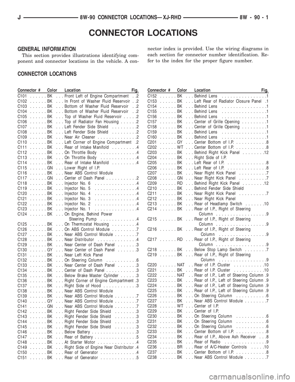
Connector # Color Location Fig.
C101......BK ...Front Left of Engine Compartment . .2
C102......BK ...InFront of Washer Fluid Reservoir . .2
C103......BK ...Bottom of Washer Fluid Reservoir . .2
C104......BK ...Bottom of Washer Fluid Reservoir . .2
C105......BK ...TopofWasher Fluid Reservoir.....2
C106......BK ...TopofRadiator Fan Housing......2
C107......BK ...Left Fender Side Shield.........2
C108......BK ...Left Fender Side Shield.........2
C109......BK ...Near Air Cleaner..............2
C110......BK ...Left Corner of Engine Compartment .2
C111......BK ...Rear of Intake Manifold.........4
C112......BK ...OnThrottle Body.............4
C113......BK ...OnThrottle Body.............4
C114......BK ...Rear of Intake Manifold.........4
C115......GN ...Lower Right of I.P.
C116......BK ...Near ABS Control Module
C117......GN ...Center of Dash Panel...........2
C118......BK ...Injector No. 6...............4
C119......BK ...Injector No. 5...............4
C120......BK ...Injector No. 4...............4
C121......BK ...Injector No. 3...............4
C122......BK ...Injector No. 2...............4
C123......BK ...Injector No. 1...............4
C124......BK ...OnEngine, Behind Power
Steering Pump.............4
C125......BK ...OnThermostat Housing.........4
C126......BK ...OnABSControl Module.........7
C127......BK ...Near ABS Control Module........7
C128......BK ...Near Distributor..............4
C129......BK ...Near Center of Dash Panel.......3
C130......GY ...Near Center of Dash Panel.......3
C131......BK ...Near Left Kick Panel
C132......BK ...OnSteering Column...........6
C133......BK ...Near Center of Dash Panel.......3
C134......BK ...Center of Dash Panel...........3
C135......BK ...Below Brake Master Cylinder......3
C136......BK ...Right Corner of Engine Compartment .3
C137......BK ...Right Side of Hood............3
C138......BK ...Near ABS Control Module
C139......BK ...Near ABS Control Module........7
C140......GY ...Near ABS Control Module........7
C141......GN ...Near ABS Control Module........7
C142......BK ...Right Fender Side Shield........3
C143......BK ...Right Fender Side Shield........3
C144......BK ...Right Fender Side Shield........3
C145......BK ...Right Fender Side Shield........3
C146......BK ...Below Battery................3
C147......BK ...Rear of Battery...............5
C148......BK ...AtStarter Motor..............4
C149......BK ...Right Side of Engine Near Distributor .4
C150......BK ...Rear of Generator.............4
C151......BK ...Rear of Generator.............5
Page 1085 of 2158

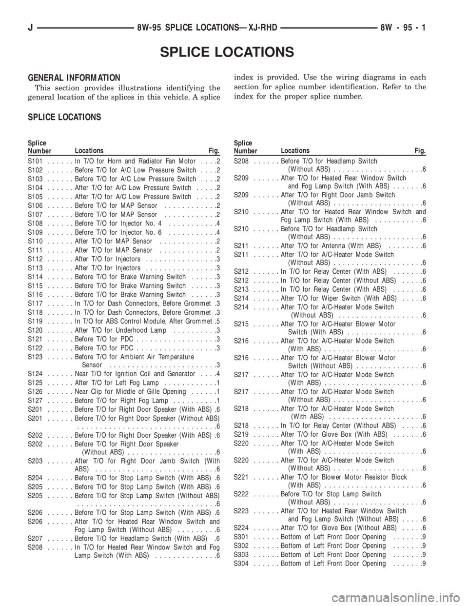
Splice
NumberLocations Fig.
S101......InT/OforHorn and Radiator Fan Motor....2
S102......Before T/O for A/C Low Pressure Switch....2
S103......Before T/O for A/C Low Pressure Switch....2
S104......After T/O for A/C Low Pressure Switch.....2
S105......After T/O for A/C Low Pressure Switch.....2
S106......Before T/O for MAP Sensor............2
S107......Before T/O for MAP Sensor............2
S108......Before T/O for Injector No. 4...........4
S109......Before T/O for Injector No. 6...........4
S110......After T/O for MAP Sensor.............2
S111......After T/O for MAP Sensor.............2
S112......After T/O for Injectors................3
S113......After T/O for Injectors................3
S114......Before T/O for Brake Warning Switch......3
S115......Before T/O for Brake Warning Switch......3
S116......Before T/O for Brake Warning Switch......3
S117......InT/OforDash Connectors, Before Grommet .3
S118......InT/OforDash Connectors, Before Grommet .3
S119......InT/OforABSControl Module, After Grommet .5
S120......After T/O for Underhood Lamp..........3
S121......Before T/O for PDC..................3
S122......Before T/O for PDC..................3
S123......Before T/O for Ambient Air Temperature
Sensor........................3
S124......Near T/O for Ignition Coil and Generator....4
S125......After T/O for Left Fog Lamp............1
S126......Near Clip for Middle of Gille Opening......1
S127......Before T/O for Right Fog Lamp..........1
S201......Before T/O for Right Door Speaker (With ABS) .6
S201......Before T/O for Right Door Speaker (Without ABS)
...............................6
S202......Before T/O for Right Door Speaker (With ABS) .6
S202......Before T/O for Right Door Speaker
(Without ABS)....................6
S203......After T/O for Right Door Jamb Switch (With
ABS)...........................6
S204......Before T/O for Stop Lamp Switch (With ABS) .6
S205......Before T/O for Stop Lamp Switch (With ABS) .6
S205......Before T/O for Stop Lamp Switch (Without ABS)
...............................6
S206......Before T/O for Stop Lamp Switch (With ABS) .6
S206......After T/O for Heated Rear Window Switch and
Fog Lamp Switch (Without ABS).........6
S207......Before T/O for Headlamp Switch (With ABS) .6
S208......InT/OforHeated Rear Window Switch and Fog
Lamp Switch (With ABS)..............6
Page 1297 of 2158
Fig. 15 Upper Radiator Hose, Coolant Recovery
Hose & Fan Shroud
9 - 18 2.5L ENGINEJ