1995 JEEP CHEROKEE FLASH RELAY
[x] Cancel search: FLASH RELAYPage 172 of 2198
ABS DIAGNOSTIC CONNECTOR
The ABS diagnostic connector is inside the vehicle.
The connector is the access point for the DRB scan
tool.
On XJ models, the connector is located under the
instrument panel to the right of the steering column.
On some models, the connecter may be tucked under
the carpeting on the transmission tunnel. The con-
necter is a black, 6-way type.
On YJ models, the connector is under the instru-
ment panel by the the driver side kick panel. The
connecter is a black, 6 or 8-way type.
The DRB scan tool kit contains adapter cords for
both types of connecter. Use the appropriate cord for
test hookup.
ACCELERATION SWITCH
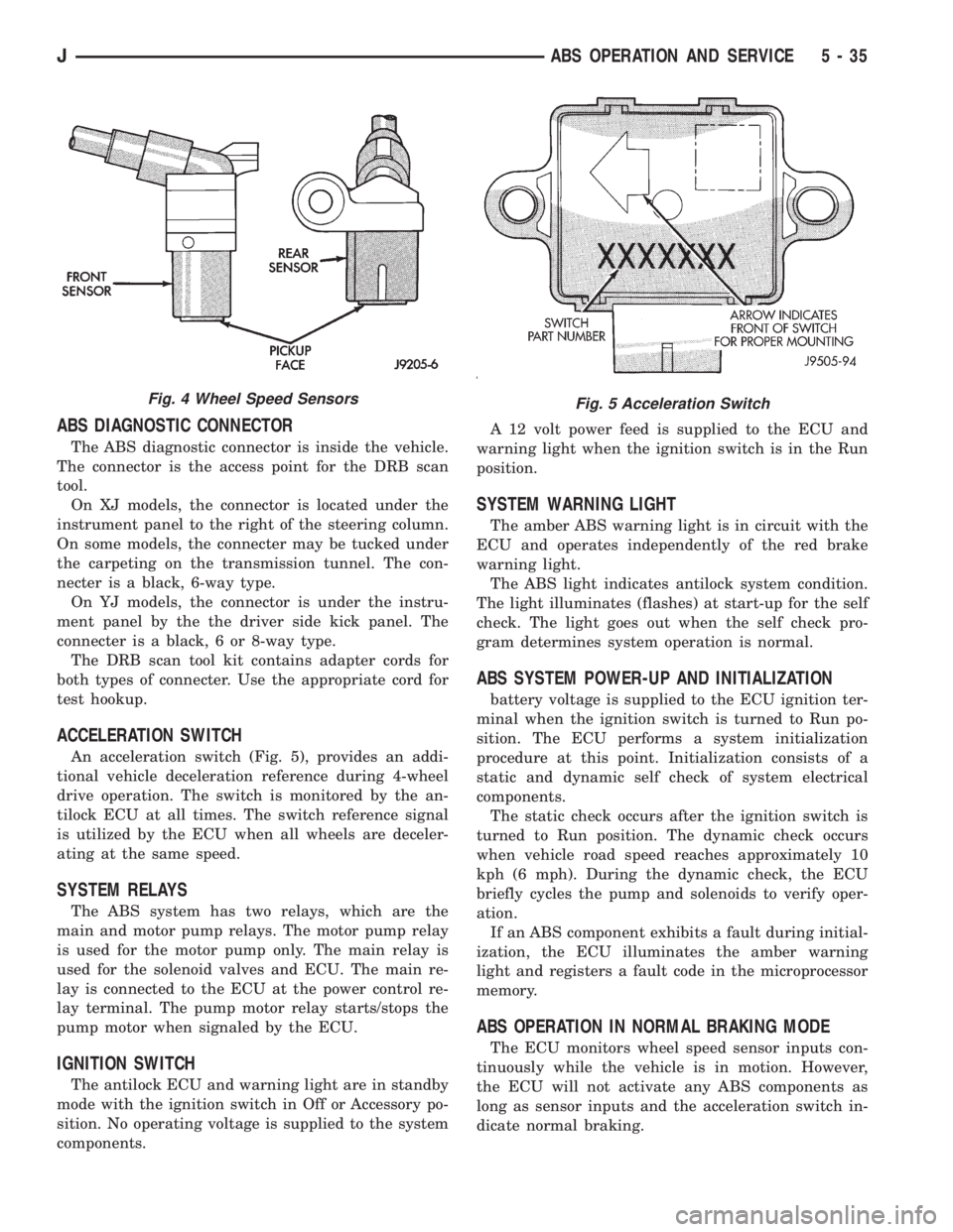
An acceleration switch (Fig. 5), provides an addi-
tional vehicle deceleration reference during 4-wheel
drive operation. The switch is monitored by the an-
tilock ECU at all times. The switch reference signal
is utilized by the ECU when all wheels are deceler-
ating at the same speed.
SYSTEM RELAYS
The ABS system has two relays, which are the
main and motor pump relays. The motor pump relay
is used for the motor pump only. The main relay is
used for the solenoid valves and ECU. The main re-
lay is connected to the ECU at the power control re-
lay terminal. The pump motor relay starts/stops the
pump motor when signaled by the ECU.
IGNITION SWITCH
The antilock ECU and warning light are in standby
mode with the ignition switch in Off or Accessory po-
sition. No operating voltage is supplied to the system
components.A 12 volt power feed is supplied to the ECU and
warning light when the ignition switch is in the Run
position.
SYSTEM WARNING LIGHT
The amber ABS warning light is in circuit with the
ECU and operates independently of the red brake
warning light.
The ABS light indicates antilock system condition.
The light illuminates (flashes) at start-up for the self
check. The light goes out when the self check pro-
gram determines system operation is normal.
ABS SYSTEM POWER-UP AND INITIALIZATION
battery voltage is supplied to the ECU ignition ter-
minal when the ignition switch is turned to Run po-
sition. The ECU performs a system initialization
procedure at this point. Initialization consists of a
static and dynamic self check of system electrical
components.
The static check occurs after the ignition switch is
turned to Run position. The dynamic check occurs
when vehicle road speed reaches approximately 10
kph (6 mph). During the dynamic check, the ECU
briefly cycles the pump and solenoids to verify oper-
ation.
If an ABS component exhibits a fault during initial-
ization, the ECU illuminates the amber warning
light and registers a fault code in the microprocessor
memory.
ABS OPERATION IN NORMAL BRAKING MODE
The ECU monitors wheel speed sensor inputs con-
tinuously while the vehicle is in motion. However,
the ECU will not activate any ABS components as
long as sensor inputs and the acceleration switch in-
dicate normal braking.
Fig. 4 Wheel Speed SensorsFig. 5 Acceleration Switch
JABS OPERATION AND SERVICE 5 - 35
Page 260 of 2198
(5) Be sure that the air conditioner (if equipped) is
turned off.
WARNING: USE EXTREME CAUTION WHEN THE
ENGINE IS OPERATING. DO NOT STAND IN A DI-
RECT LINE WITH THE FAN. DO NOT PUT YOUR
HANDS NEAR THE PULLEYS, BELTS OR FAN. DO
NOT WEAR LOOSE CLOTHING.
(6) Start the engine and operate at 2400 rpm.
Within ten minutes the air temperature (indicated on
the dial thermometer) should be up to 88É C (190É F).
Fan driveengagementshould have started to occur
at between 74É to 82É C (165É to 180É F). Engage-
ment is distinguishable by a definiteincreasein fan
flow noise (roaring). The timing light also will indi-
cate an increase in the speed of the fan.
(7) When the air temperature reaches 88É C (190É
F), remove the plastic sheet. Fan drivedisengage-
mentshould have started to occur at between 57É to
79É C (135É to 175É F). A definitedecreaseof fan
flow noise (roaring) should be noticed. If not, replace
the defective viscous fan drive unit.
VISCOUS FAN DRIVE REMOVAL/INSTALLATION
Refer to the previous section on Cooling System
Fan for removal and installation procedures of the
viscous drive unit.
Viscous Fan Drive Fluid Pump Out Require-
ment:After installing anewviscous fan drive, bring
the engine speed up to approximately 2000 rpm and
hold for approximately two minutes. This will ensure
proper fluid distribution within the drive.
AUXILIARY ELECTRIC COOLING FANÐXJ MODELS
WITH 4.0L 6-CYLINDER ENGINE
OPERATION
XJ models equipped with a 4.0L 6-cylinder engine
may also have an auxiliary electrical cooling fan.
This is with models that have air conditioning and/or
heavy duty cooling. The fan is controlled by the cool-
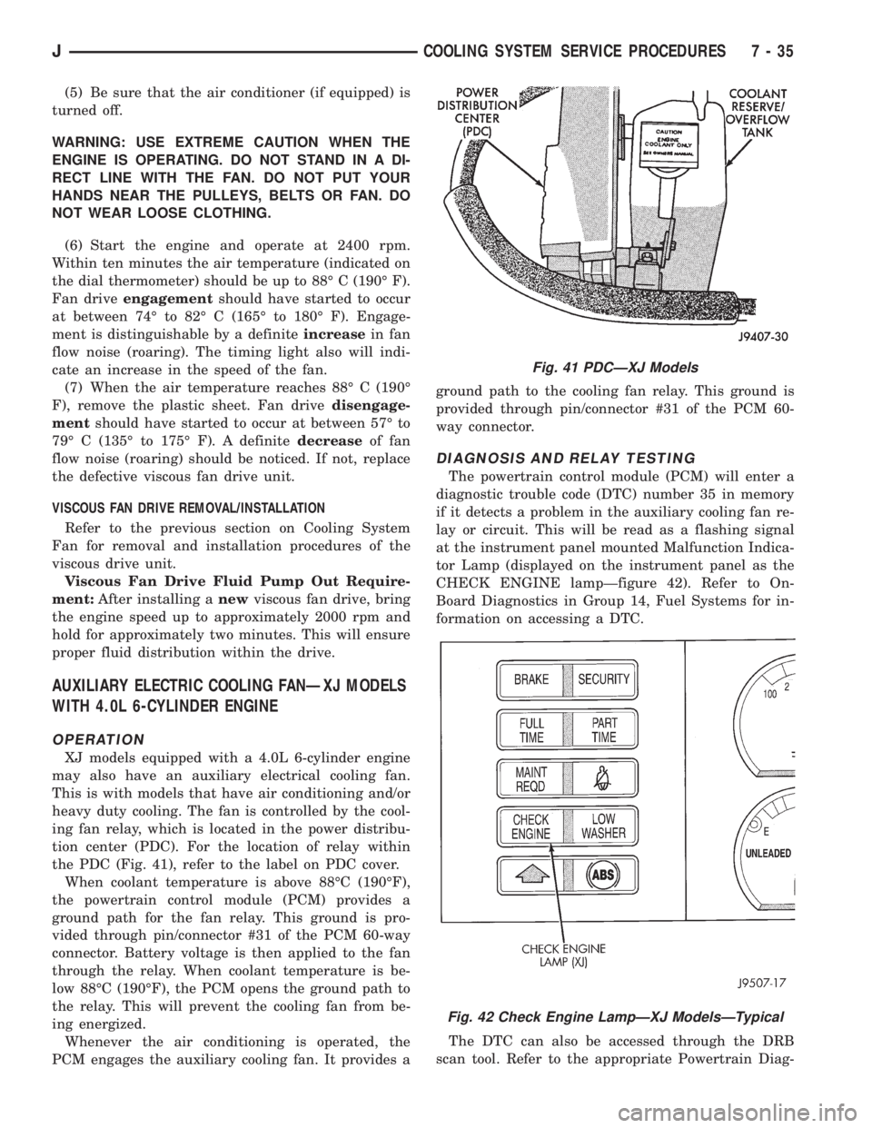
ing fan relay, which is located in the power distribu-
tion center (PDC). For the location of relay within
the PDC (Fig. 41), refer to the label on PDC cover.
When coolant temperature is above 88ÉC (190ÉF),
the powertrain control module (PCM) provides a
ground path for the fan relay. This ground is pro-
vided through pin/connector #31 of the PCM 60-way
connector. Battery voltage is then applied to the fan
through the relay. When coolant temperature is be-
low 88ÉC (190ÉF), the PCM opens the ground path to
the relay. This will prevent the cooling fan from be-
ing energized.
Whenever the air conditioning is operated, the
PCM engages the auxiliary cooling fan. It provides aground path to the cooling fan relay. This ground is
provided through pin/connector #31 of the PCM 60-
way connector.
DIAGNOSIS AND RELAY TESTING
The powertrain control module (PCM) will enter a
diagnostic trouble code (DTC) number 35 in memory
if it detects a problem in the auxiliary cooling fan re-
lay or circuit. This will be read as a flashing signal
at the instrument panel mounted Malfunction Indica-
tor Lamp (displayed on the instrument panel as the
CHECK ENGINE lampÐfigure 42). Refer to On-
Board Diagnostics in Group 14, Fuel Systems for in-
formation on accessing a DTC.
The DTC can also be accessed through the DRB
scan tool. Refer to the appropriate Powertrain Diag-
Fig. 41 PDCÐXJ Models
Fig. 42 Check Engine LampÐXJ ModelsÐTypical
JCOOLING SYSTEM SERVICE PROCEDURES 7 - 35
Page 326 of 2198
To test ignition coil-to-distributor cap cable, do not
remove the cable from the cap. Connect ohmmeter to
rotor button (center contact) of distributor cap and
terminal at ignition coil end of cable. If resistance is
not within specifications as found in the Spark Plug
Cable Resistance chart, remove the cable from the
distributor cap. Connect the ohmmeter to the termi-
nal ends of the cable. If resistance is not within spec-
ifications as found in the Spark Plug Cable
Resistance chart, replace the cable. Inspect the igni-
tion coil tower for cracks, burns or corrosion.
For removal and installation of spark plug cables,
refer to Spark Plug Secondary Cables in the Compo-
nent Removal/Installation section.
THROTTLE POSITION SENSOR TEST
For an operational description, diagnosis and re-
moval/installation procedures, refer to Group 14,
Fuel System.
OXYGEN (O2S) SENSOR TESTS
For an operational description, diagnosis or remov-
al/ installation procedures, refer to Group 14, Fuel
Systems.
ON-BOARD DIAGNOSTICS
FOR CERTAIN IGNITION SYSTEM
COMPONENTS
The powertrain control module (PCM) performs an
On-Board Diagnostic (OBD) check for certain ignition
system components on all vehicles. This is done by
setting a diagnostic trouble code (DTC).
A DTC can be obtained in two different ways. One
of the ways is by connecting the DRB scan tool to the
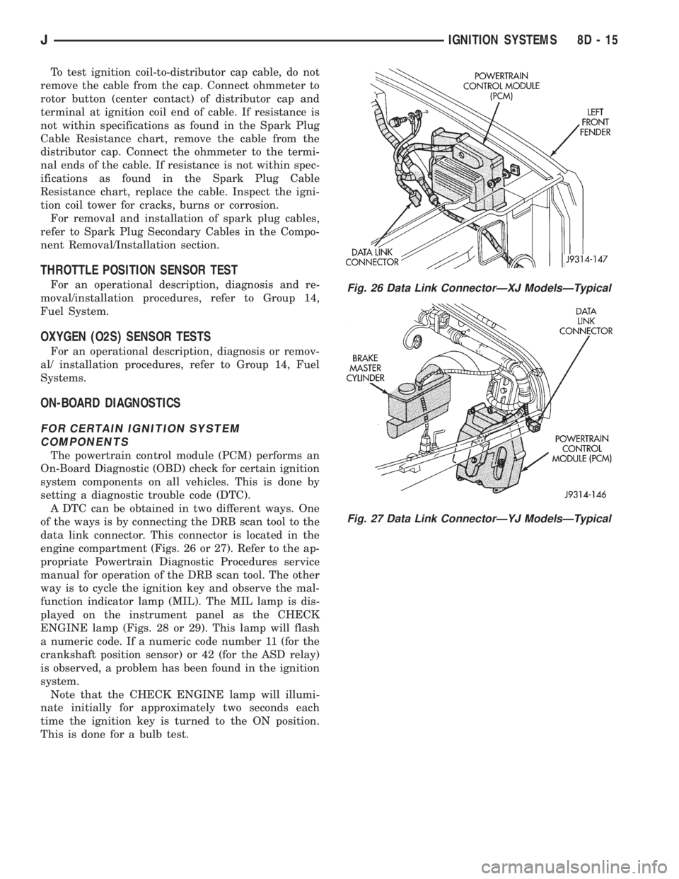
data link connector. This connector is located in the
engine compartment (Figs. 26 or 27). Refer to the ap-
propriate Powertrain Diagnostic Procedures service
manual for operation of the DRB scan tool. The other
way is to cycle the ignition key and observe the mal-
function indicator lamp (MIL). The MIL lamp is dis-
played on the instrument panel as the CHECK
ENGINE lamp (Figs. 28 or 29). This lamp will flash
a numeric code. If a numeric code number 11 (for the
crankshaft position sensor) or 42 (for the ASD relay)
is observed, a problem has been found in the ignition
system.
Note that the CHECK ENGINE lamp will illumi-
nate initially for approximately two seconds each
time the ignition key is turned to the ON position.
This is done for a bulb test.
Fig. 26 Data Link ConnectorÐXJ ModelsÐTypical
Fig. 27 Data Link ConnectorÐYJ ModelsÐTypical
JIGNITION SYSTEMS 8D - 15
Page 415 of 2198
allowing current flow to the lamps. As the bimetal
strip cools, the contact points are pushed open and
the cycle repeats.
COMBINATION FLASHER (XJ ONLY)
The combination flasher functions as both the turn
signal and hazard warning flasher on XJ models. The
combination flasher is a smart relay that is located in
the relay center under the lower instrument panel
and inboard of the steering column. The combination
flasher can not be repaired. If faulty, it must be
replaced.
The combination flasher is designed to handle the
current flow requirements of the factory installed
lighting. If supplemental lighting is added to the turn
signal circuits such as when towing a trailer with
lights, the combination flasher will automatically
compensate. This allows the flash rate to remain the
same, regardless of electrical load increases. However,
if a bulb fails in the turn signal or hazard warning
circuits, the flash rate of the remaining bulbs in that
circuit will increase to 120 flashes per minute or
higher.
TURN SIGNAL/HAZARD WARNING SWITCH
(YJ ONLY)
The turn signal and hazard warning switches are
combined into a single unit mounted within the upper
steering column bowl and beneath the steering wheel.
The turn signal lever on the left side of the steering
column is moved up or down to select the right or left
turn signal switch position. The turn signals will only
operate with the ignition switch in the ACCESSORY
or ON position.
The hazard warning button on the right side of the
steering column is pushed in to turn the hazard
warning system on, or pulled out to turn the system
off. The hazard warning system will operate regard-
less of ignition switch position. The turn signal/haz-
ard warning switch can not be repaired. If faulty, the
entire unit must be replaced.
MULTI-FUNCTION SWITCH (XJ ONLY)
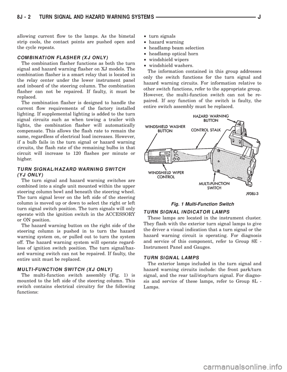
The multi-function switch assembly (Fig. 1) is
mounted to the left side of the steering column. This
switch contains electrical circuitry for the following
functions:²turn signals
²hazard warning
²headlamp beam selection
²headlamp optical horn
²windshield wipers
²windshield washers.
The information contained in this group addresses
only the switch functions for the turn signal and
hazard warning circuits. For information relative to
other switch functions, refer to the appropriate group.
However, the multi-function switch can not be re-
paired. If any function of the switch is faulty, the
entire switch assembly must be replaced.
TURN SIGNAL INDICATOR LAMPS
These lamps are located in the instrument cluster.
They flash with the exterior turn signal lamps to give
the driver a visual indication that a turn signal or the
hazard warning circuit is operating. For diagnosis
and service of this component, refer to Group 8E -
Instrument Panel and Gauges.
TURN SIGNAL LAMPS
The exterior lamps included in the turn signal and
hazard warning circuits include: the front park/turn
signal, and the rear tail/stop/turn signal. For diagno-
sis and service of these lamps, refer to Group 8L -
Lamps.
Fig. 1 Multi-Function Switch
8J - 2 TURN SIGNAL AND HAZARD WARNING SYSTEMSJ
Page 416 of 2198
DIAGNOSIS
When diagnosing the turn signal or hazard warning
circuits, remember that high generator output can
burn out bulbs rapidly and repeatedly. If this is a
problem on the vehicle being diagnosed, refer to
Group 8A - Battery/Starting/Charging Systems Diag-
nostics to test charging system.
WARNING: ON VEHICLES EQUIPPED WITH AN AIR-
BAG, REFER TO GROUP 8M - RESTRAINT SYS-
TEMS BEFORE ATTEMPTING STEERING WHEEL
COMPONENT DIAGNOSIS OR SERVICE. FAILURE
TO TAKE PROPER PRECAUTIONS COULD RESULT
IN ACCIDENTAL AIRBAG DEPLOYMENT AND POS-
SIBLE PERSONAL INJURY.
TURN SIGNAL/HAZARD WARNING SYSTEM - XJ
(1) Turn ignition switch to ON position. Actuate the
turn signal lever or hazard warning button. Observe
the turn indicator lamp(s) in the instrument cluster.
If the flash rate is very high, check for a turn signal
bulb that is not lit. Replace that bulb or repair cir-
cuits to that lamp, as required. Test operation. If turn
indicator does not light, continue to next step.
(2) Remove and inspect fuse 8 (turn signals) in
fuseblock module, or fuse F13 (hazard warning) in the
Power Distribution Center. Replace fuse, if required.
(3) Remove combination flasher from relay center
and replace with a known good unit. Test operation of
turn signal and hazard warning systems. If OK, re-place faulty combination flasher. If not OK, remove
test flasher and go to next step.
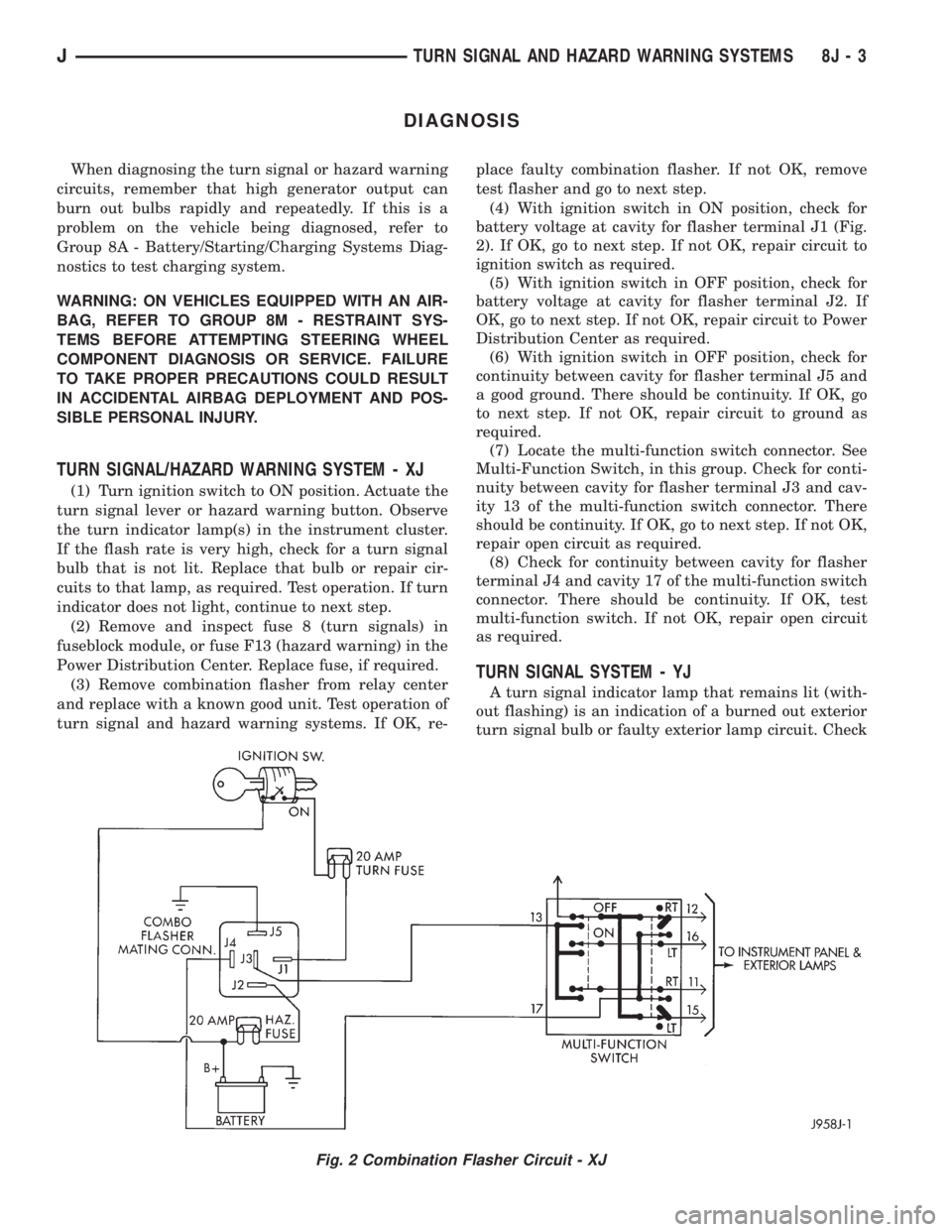
(4) With ignition switch in ON position, check for
battery voltage at cavity for flasher terminal J1 (Fig.
2). If OK, go to next step. If not OK, repair circuit to
ignition switch as required.
(5) With ignition switch in OFF position, check for
battery voltage at cavity for flasher terminal J2. If
OK, go to next step. If not OK, repair circuit to Power
Distribution Center as required.
(6) With ignition switch in OFF position, check for
continuity between cavity for flasher terminal J5 and
a good ground. There should be continuity. If OK, go
to next step. If not OK, repair circuit to ground as
required.
(7) Locate the multi-function switch connector. See
Multi-Function Switch, in this group. Check for conti-
nuity between cavity for flasher terminal J3 and cav-
ity 13 of the multi-function switch connector. There
should be continuity. If OK, go to next step. If not OK,
repair open circuit as required.
(8) Check for continuity between cavity for flasher
terminal J4 and cavity 17 of the multi-function switch
connector. There should be continuity. If OK, test
multi-function switch. If not OK, repair open circuit
as required.
TURN SIGNAL SYSTEM - YJ
A turn signal indicator lamp that remains lit (with-
out flashing) is an indication of a burned out exterior
turn signal bulb or faulty exterior lamp circuit. Check
Fig. 2 Combination Flasher Circuit - XJ
JTURN SIGNAL AND HAZARD WARNING SYSTEMS 8J - 3
Page 544 of 2198
POWER DISTRIBUTION
GENERAL INFORMATION
This section covers the Power Distribution Center
(PDC) and all circuits involved with it. For additional
information on system operation, refer to the appro-
priate section of the wiring diagrams.
DIAGRAM INDEX
Component Page
A/C Compressor Clutch Relay..............8W-11-3, 11
ABS Control Module.....................8W-11-6, 7
ABS Power Relay......................8W-11-3, 6
ABS Pump Motor Relay..................8W-11-3, 7
Automatic Shut Down Relay................8W-11-3, 9
Chime/Buzzer Module..................8W-11-10, 14
Circuit Breaker Cavity 16 (Fuse Block)..........8W-11-13
Combination Flasher......................8W-11-17
Daytime Running Lamp Module.............8W-11-5, 10
Diode D101............................8W-11-6
Engine Starter Motor Relay................8W-11-3, 4
Fuel Pump Relay.......................8W-11-3, 8
Fuse 1 (PDC)..........................8W-11-13
Fuse 3 (PDC)..........................8W-11-12
Fuse 4 (Fuse Block)......................8W-11-14
Fuse 4 (PDC)..........................8W-11-15
Fuse 5 (PDC)..........................8W-11-14
Fuse 6 (PDC)....................8W-11-4, 7, 10, 15
Fuse 7 (Fuse Block).......................8W-11-7
Fuse 7 (PDC)...........................8W-11-4
Fuse 8 (PDC)...........................8W-11-7
Fuse 9 (Fuse Block)......................8W-11-12
Fuse 9 (PDC)..........................8W-11-13
Fuse 10 (PDC)........................8W-11-6, 8
Fuse 11 (Fuse Block).....................8W-11-13
Fuse 11 (PDC).........................8W-11-10
Fuse 12 (PDC).........................8W-11-15Component Page
Fuse 13 (PDC)..........................8W-11-4
Fuse 14 (PDC)..........................8W-11-8
Fuse 15 (Fuse Block).....................8W-11-14
Fuse 15 (PDC)..........................8W-11-8
Fuse 16 (PDC).........................8W-11-12
Fuse 17 (Fuse Block).....................8W-11-10
Headlamp Delay Module.................8W-11-10, 14
Headlamp Switch........................8W-11-14
Headlamp Dimmer Switch..................8W-11-14
Horn Rear Window Relay..................8W-11-17
Horn Relay............................8W-11-17
Ignition Switch...................8W-11-4, 7, 10, 15
In-Line Circuit Breaker (Stop Lamp Relay)........8W-11-13
LCD Illumination Relay....................8W-11-17
Overhead Console.....................8W-11-10, 14
Powertrain Control Module..........8W-11-4, 5, 8, 9, 11
Power Distribution Center...................8W-11-2
Power Door Lock Relay...................8W-11-16
Power Door Unlock Relay..................8W-11-16
Radiator Fan Control Relay................8W-11-3, 11
Remote Keyless Entry Module.............8W-11-10, 12
Relay Center...........................8W-11-16
Telltale Connector (I.P. Cluster)..........8W-11-6, 10, 12
Torque Converter Clutch (TCC) Relay...........8W-11-15
Transmission Control Module...............8W-11-5, 8
J8W-11 POWER DISTRIBUTIONÐXJ VEHICLES 8W - 11 - 1
Page 660 of 2198

FRONT LIGHTING
INDEX
page page
Daytime Running Lamp (DRL) Module........... 2
Diagram Index............................ 2
Fog Lamps............................... 1Headlamp Delay Module..................... 2
Headlamps............................... 1
Parking Lamps............................ 1
HEADLAMPS
The headlamp switch has three positions: ON,
PARK (parking lamps) and OFF. Circuit A3 from fuse
5 in the PDC connects to the headlamp switch and
feeds the circuit L7 through fuse 15 in the fuse block.
Circuit L7 connects to the headlamp switch.
Circuit A3 also splices to feed circuit L11 through
fuse 4 in the fuse block. Circuit L11 connects to the
dimmer switch circuitry in the multi-function switch.
Circuit A3 from fuse 5 in the PDC supplies battery
voltage to the headlamp switch. The headlamp switch
has an internal circuit breaker that connects circuit
A3 to circuit F34. Circuit F34 connects to the dimmer
switch circuitry in the multi-function switch.
HEADLAMP SWITCH IN OFF OR PARKING
LAMP POSITION
Circuit L11 connects to the dimmer switch portion
of the multi-function switch. Circuit L11 supplies
power for the high beams on circuit L3 when the
operator flashes the headlamps with the turn signal
stalk of the multi-function switch.
HEADLAMP SWITCH IN ON POSITION
When the headlamp switch is in the ON position,
circuit A3 from fuse 5 in the Power Distribution Cen-
ter (PDC) connects to circuit F34. Circuit F34 con-
nects to the dimmer switch portion of the multi-
function switch and feeds circuit L4. Circuit L4
powers the low beam of the headlamps.
When the operator selects high beam operation
with the turn signal stalk of the multi-function
switch, circuit L11 connects to the L3 circuit. Circuit
L3 powers high beam operation.
HEADLAMP GROUND
Circuit Z1 provides ground for both the right and
left headlamps. Circuit Z1 also supplies ground for
the fog lamps, if equipped.
HELPFUL INFORMATION
²Check fuse 5 in the PDC.
²The headlamp switch has an internal circuit
breaker.
PARKING LAMPS
Circuit A3 from fuse 5 in the Power DistributionCenter (PDC) connects to a bus bar in the fuse block
which feeds circuit L7. Fuse 15 in the fuse block
protects circuit L7.
The headlamp switch has three positions: ON,
PARK (parking lamps) and OFF, plus a dimmer
switch. When the headlamp switch is in the PARK or
ON position, the switch connects circuit L7 to circuit
L90. From the headlamp switch, circuit L90 branches
to power the front parking lamps and rear tail lamps,
side marker lamps, and rear license plate lamps.
GROUND CIRCUIT
Circuit Z1 provides a ground for the parking lamps
and turn signal lamps. The Z1 circuit also provide
ground for the headlamps.
HELPFUL INFORMATION
²Check fuse 5 in the PDC.
²Check fuse 15 in the fuse block.
²When the headlamp switch is in the PARK or ON
position, the dimmer circuit, L7, also connects to cir-
cuit E2. Circuit E2 continues through fuse 19 in the
fuse block. Circuit E2 powers the illumination lamps.
FOG LAMPS
The fog lamps are controlled by the fog lamp
switch, park lamp relay and high beam relay. The fog
lamps operate only when the headlamp switch is in
the ON position, and the operator has selected low-
beam operation. When the headlamps are in high-
beam operation, the fog lamps will not operate.
Circuit F39 from fuse 5 in the Power Distribution
Center (PDC) supplies voltage to the contact side of
the park lamp relay.
Circuit L90 supplies power to the coil side of the
park lamp relay. Circuit L35 connects to the coil side
of the relay and to circuit Z1 through the fog lamp
switch. Ground for the coil side of the relay is pro-
vided on circuit Z1 through the fog lamp switch.
When the fog lamp switch closes, the park lamp
relay contacts close and circuit F39 passes through
the relay to power the contact side of the high beam
relay. When the headlamp high beams are OFF, the
high beam relay is not energized and voltage flows
through the normally closed contacts to circuit L39.
J8W-50 FRONT LIGHTINGÐXJ VEHICLES 8W - 50 - 1
Page 661 of 2198
Circuit L39 supplies voltage to the fog lamps. Cir-
cuit Z1 provides ground for the fog lamps.
If the high beam lamps are ON, circuit G465 ener-
gizes the high beam relay. When the high beam relay
energizes, the contacts open and power is not sup-
plied to the fog lamps. Circuit Z1 provides ground for
the coil side of the high beam relay.
Circuit E2 provides voltage for the illumination
lamp in the fog lamp switch.
HELPFUL INFORMATION
²Circuit L3 splices to power circuit G465. Circuit
L3 powers the high beam circuit of the headlamps.
HEADLAMP DELAY MODULE
When the operator turns off the ignition switch and
the headlamp switch, the headlamp delay module
powers the headlamps for approximately 45 seconds.
When the ignition switch is in the RUN position,
circuit A21 powers circuit F87 through fuse 17 in the
fuse block. Circuit F87 supplies the IGNITION ON/
OFF signal to the headlamp delay module. Circuit Z1
provides ground for the module.
When the headlamp delay module activates, it con-
nects circuit X4 from fuse 11 in the fuse block to cir-
cuit F34. Circuit F34 powers the headlamps through
the headlamp dimmer switch circuit L3.
HELPFUL INFORMATION
Circuit A7 from fuse 3 in the PDC supplies voltage
to the fuse block bus bar that powers circuit X4
through the fuse in cavity 11.
DAYTIME RUNNING LAMP (DRL) MODULE
On vehicles built for sale in Canada, the low-beam
headlamps operate when the ignition switch is in the
RUN position.
When the ignition switch is in the RUN position,
circuit A1 from fuse 6 in the Power Distribution Cen-
ter (PDC), connects to circuit A21. Circuit A21 splices
to supply power to the DRL module.
Circuit A3 from fuse 5 in the PDC connects to DRL
module. Circuit A3 is HOT at all times.The DRL module receives the vehicle speed sensor
input from circuit G7. Circuit G465 from the DRL
module splices to circuit L3 to provide power for the
high beam indicator lamp in the instrument cluster.
Circuit L4 powers the low beams of the left and
right headlamps. When the headlamp switch is OFF,
the DRL module powers the low beams on circuit L4.
When the headlamps are ON, the dimmer switch in
the multi-function switch powers the low beams on
circuit L4.
Circuit L3 feeds the high beams of the headlamps.
When the operator flashes the headlamps with the
stalk of the multi-function switch, the DRL senses
voltage on circuit L3. When it senses voltage on cir-
cuit L3, the DRL module stops supplying power to
the low beams on circuit L4.
Circuit Z12 provides ground for the DRL module.
DIAGRAM INDEX
Component Page
Chime/Buzzer Module......................8W-50-8
Daytime Running Lamps (DRL) Module..........8W-50-3
Fog Lamps.............................8W-50-7
Fog Lamp Switch........................8W-50-7
Fuse 3 (PDC)...........................8W-50-9
Fuse 4 (Fuse Block).......................8W-50-9
Fuse 5 (PDC).....................8W-50-2, 3, 6, 9
Fuse 6 (PDC).........................8W-50-2, 8
Fuse 7 (PDC)...........................8W-50-6
Fuse 11 (Fuse Block)......................8W-50-9
Fuse 13 (PDC)..........................8W-50-6
Fuse 15 (Fuse Block)....................8W-50-3, 6
Fuse 17 (Fuse Block)......................8W-50-8
Fuse 19 (Fuse Block)......................8W-50-6
Headlamps.............................8W-50-5
Headlamp Dimmer Switch.................8W-50-4, 9
Headlamp Switch.....................8W-50-4, 6, 9
High Beam Relay.........................8W-50-7
Ignition Switch........................8W-50-3, 8
Park Lamp Relay.........................8W-50-6
Side Marker Lamps.......................8W-50-5
Tail, Stop and Turn Signal Lamps..............8W-50-5
Telltale Connector (Instrument Cluster)...........8W-50-9
8W - 50 - 2 8W-50 FRONT LIGHTINGÐXJ VEHICLESJ