Page 1576 of 2198

TORQUE CONVERTER STATOR CLUTCH
INSPECTION
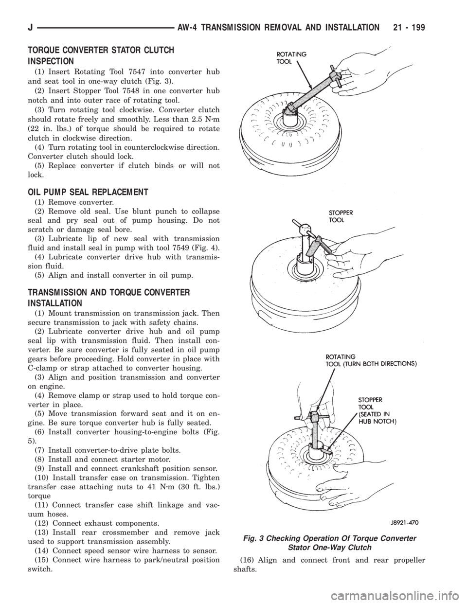
(1) Insert Rotating Tool 7547 into converter hub
and seat tool in one-way clutch (Fig. 3).
(2) Insert Stopper Tool 7548 in one converter hub
notch and into outer race of rotating tool.
(3) Turn rotating tool clockwise. Converter clutch
should rotate freely and smoothly. Less than 2.5 Nzm
(22 in. lbs.) of torque should be required to rotate
clutch in clockwise direction.
(4) Turn rotating tool in counterclockwise direction.
Converter clutch should lock.
(5) Replace converter if clutch binds or will not
lock.
OIL PUMP SEAL REPLACEMENT
(1) Remove converter.
(2) Remove old seal. Use blunt punch to collapse
seal and pry seal out of pump housing. Do not
scratch or damage seal bore.
(3) Lubricate lip of new seal with transmission
fluid and install seal in pump with tool 7549 (Fig. 4).
(4) Lubricate converter drive hub with transmis-
sion fluid.
(5) Align and install converter in oil pump.
TRANSMISSION AND TORQUE CONVERTER
INSTALLATION
(1) Mount transmission on transmission jack. Then
secure transmission to jack with safety chains.
(2) Lubricate converter drive hub and oil pump
seal lip with transmission fluid. Then install con-
verter. Be sure converter is fully seated in oil pump
gears before proceeding. Hold converter in place with
C-clamp or strap attached to converter housing.
(3) Align and position transmission and converter
on engine.
(4) Remove clamp or strap used to hold torque con-
verter in place.
(5) Move transmission forward seat and it on en-
gine. Be sure torque converter hub is fully seated.
(6) Install converter housing-to-engine bolts (Fig.
5).
(7) Install converter-to-drive plate bolts.
(8) Install and connect starter motor.
(9) Install and connect crankshaft position sensor.
(10) Install transfer case on transmission. Tighten
transfer case attaching nuts to 41 Nzm (30 ft. lbs.)
torque
(11) Connect transfer case shift linkage and vac-
uum hoses.
(12) Connect exhaust components.
(13) Install rear crossmember and remove jack
used to support transmission assembly.
(14) Connect speed sensor wire harness to sensor.
(15) Connect wire harness to park/neutral position
switch.(16) Align and connect front and rear propeller
shafts.
Fig. 3 Checking Operation Of Torque Converter
Stator One-Way Clutch
JAW-4 TRANSMISSION REMOVAL AND INSTALLATION 21 - 199
Page 1578 of 2198

AW-4 TRANSMISSION OVERHAUL
INDEX
page page
Cleaning and Inspection................... 214
Direct Clutch Overhaul.................... 228
First-Reverse Brake Piston and Transmission Case
Overhaul............................. 247
Forward Clutch Overhaul................... 232
Front Planetary Gear Overhaul.............. 237
Manual Valve Shaft Overhaul............... 215
Oil Pump Overhaul....................... 216
Overdrive Planetary Gear and Clutch Overhaul . . 218Overdrive Support Overhaul................ 226
Overhaul Service Tools.................... 201
Rear Planetary, No. 2 One-Way Clutch and Output
Shaft Overhaul......................... 244
Second Brake Overhaul................... 241
Sun Gear and No. 1 One-Way Clutch Overhaul . . 238
Transmission Assembly and Adjustment........ 265
Transmission Disassembly................. 201
Transmission Valve Body Overhaul........... 250
OVERHAUL SERVICE TOOLS
The special tools needed to overhaul the AW-4
transmission are provided in Tool Kit 6294. However,
Pressure Test Port Adapter 7554 is not included in
this kit and must be ordered separately. The over-
haul tool kit and test port adapter are available
through the parts division and dealer special tool
program.
TRANSMISSION DISASSEMBLY
(1) Remove torque converter.
(2) Remove lower half of filler tube if not previ-
ously removed.
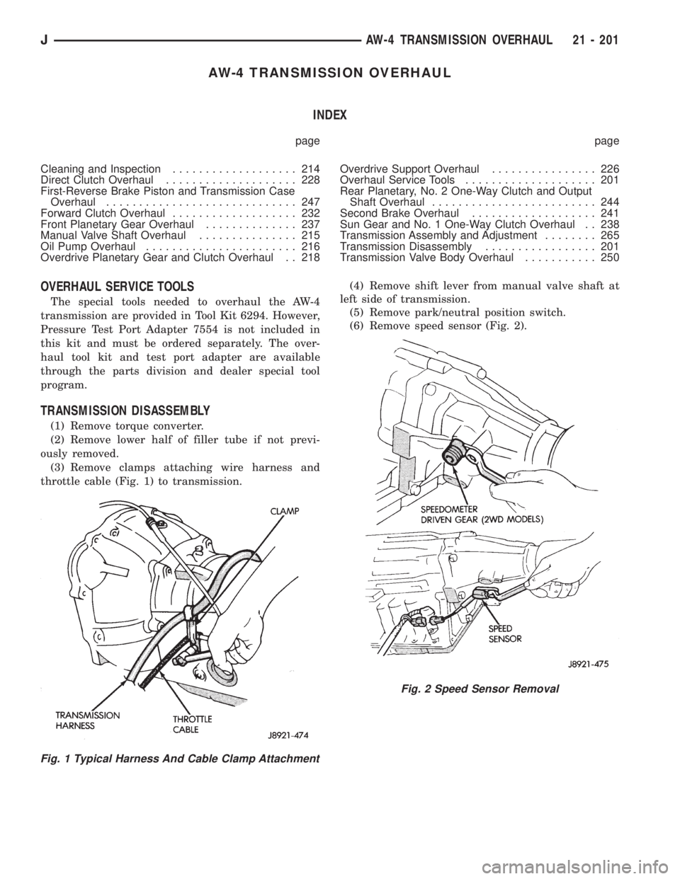
(3) Remove clamps attaching wire harness and
throttle cable (Fig. 1) to transmission.(4) Remove shift lever from manual valve shaft at
left side of transmission.
(5) Remove park/neutral position switch.
(6) Remove speed sensor (Fig. 2).
Fig. 1 Typical Harness And Cable Clamp Attachment
Fig. 2 Speed Sensor Removal
JAW-4 TRANSMISSION OVERHAUL 21 - 201
Page 1594 of 2198
rear. Replace stator shaft if bushing diameter is
greater than specified.
(7) Measure oil pump clearances (Fig. 3).
²Clearance between pump driven gear and pump
body should be maximum of 0.3 mm (0.012 in).
²Clearance between tips of pump gear teeth should
be maximum of 0.3 mm (0.012 in).
²
Clearance between rear surface of pump housing and
pump gears should be maximum of 0.1 mm (0.004 in.).
(8) Replace pump body and gears if any clearance
is greater than specified.
(9) Remove old pump seal. Install new seal with
Seal Installer 7549 (Fig. 4).
(10) Lubricate and install gears in pump body.
(11) Assemble stator shaft and pump body. Tighten
shaft-to-body bolts to 10 Nzm (7 ft. lbs.) torque.
(12) Install new O-ring on pump body and new
seal rings on stator shaft.
Fig. 3 Checking Pump Gear ClearancesFig. 5 Checking Pump Gear Rotation
Fig. 4 Installing Pump Seal
JAW-4 TRANSMISSION OVERHAUL 21 - 217
Page 1595 of 2198
(13) Install pump in torque converter and check
pump gear rotation. Gears must rotate smoothly
when turned clockwise and counterclockwise.
(14) Lubricate pump O-ring and seal rings with pe-
troleum jelly.
OVERDRIVE PLANETARY GEAR AND CLUTCH
OVERHAUL
GEAR AND CLUTCH DISASSEMBLY
(1) Check operation of one-way clutch in clutch
drum. Hold drum and turn planetary shaft clockwise
and counterclockwise. Shaft should turn clockwise
freely but lock when turned counterclockwise. Re-
place one-way clutch if necessary.(2) Replace overdrive brake clutch pack if discs are
worn below thickness of 1.84 mm (0.0724 in.). This is
clutch pack that fits on clutch drum and in case.
Fig. 1 Overdrive Planetary Gear And Clutch Components
21 - 218 AW-4 TRANSMISSION OVERHAULJ
Page 1596 of 2198
(3) Remove overdrive clutch from planetary gear
(Fig. 3).(4) Remove thrust bearing and race assembly from
clutch drum (Fig. 4).
(5) Measure stroke length of clutch piston as fol-
lows:
(a) Mount oil pump on torque converter. Then
mount clutch on oil pump (Fig. 5).
Fig. 2 Checking One-Way Clutch
Fig. 3 Removing Overdrive Clutch From Gear
Fig. 4 Removing Clutch Drum Bearing And Race
Fig. 5 Assembling Converter, Pump And Clutch For
Test
JAW-4 TRANSMISSION OVERHAUL 21 - 219
Page 1631 of 2198

use shop towels or rags. Lint or foreign material from
towels or rags can interfere with valve operation.
(13) Inspect condition of lower body components.
Replace lower body if any bores are scored or cor-
roded. Replace valves, plugs or sleeves that are
scored or worn. Replace oil strainers if cut, torn or
damaged in any way.
(14) Inspect valve body springs. Replace any spring
having rusted, distorted, or collapsed coils. Measure
length of each valve body spring. Replace any spring
if free length is less than length specified in following
chart (Fig. 11).
LOWER BODY ASSEMBLY
(1) Lubricate lower body components with auto-
matic transmission fluid.
(2) Install spring and accumulator control valve in
sleeve (Fig. 11). Then install assembled components
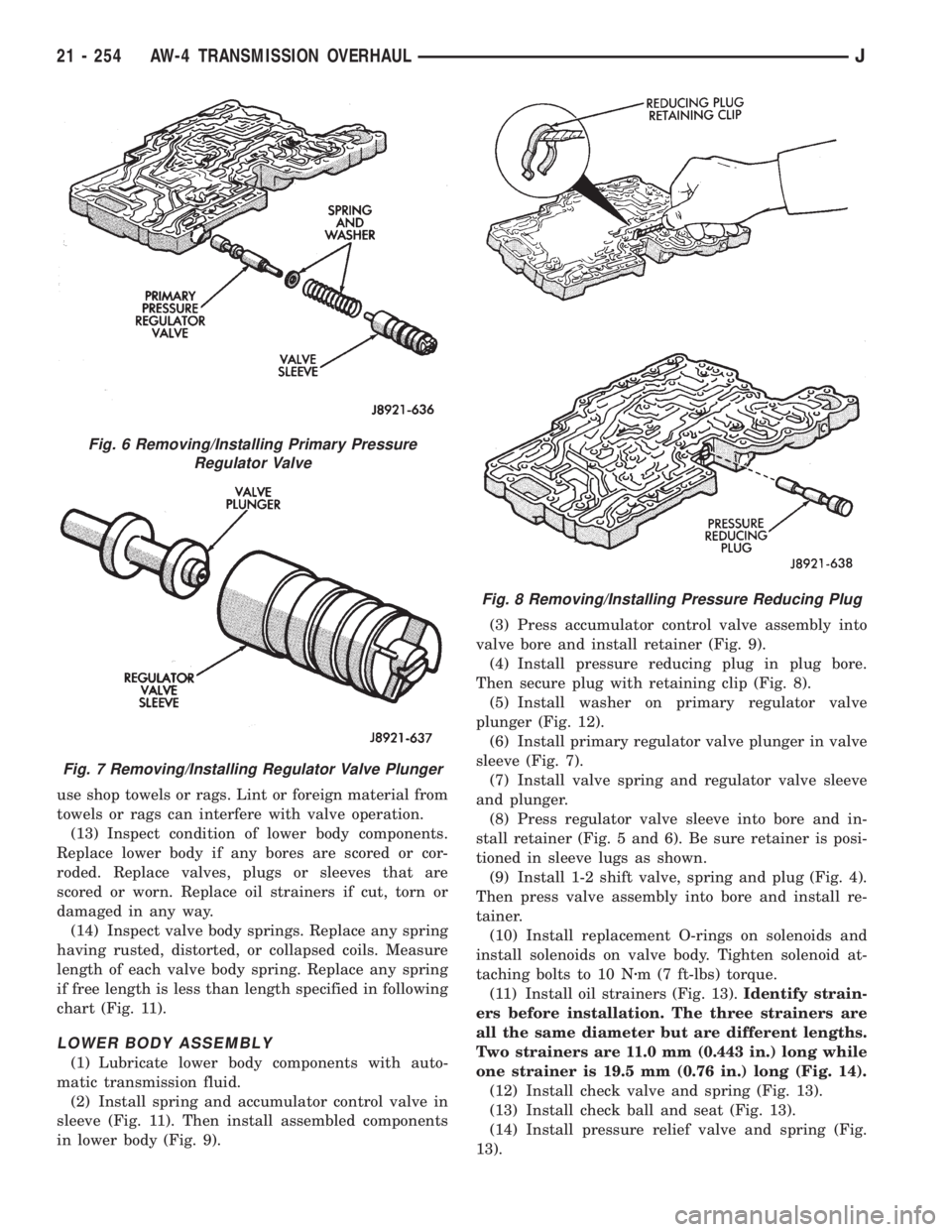
in lower body (Fig. 9).(3) Press accumulator control valve assembly into
valve bore and install retainer (Fig. 9).
(4) Install pressure reducing plug in plug bore.
Then secure plug with retaining clip (Fig. 8).
(5) Install washer on primary regulator valve
plunger (Fig. 12).
(6) Install primary regulator valve plunger in valve
sleeve (Fig. 7).
(7) Install valve spring and regulator valve sleeve
and plunger.
(8) Press regulator valve sleeve into bore and in-
stall retainer (Fig. 5 and 6). Be sure retainer is posi-
tioned in sleeve lugs as shown.
(9) Install 1-2 shift valve, spring and plug (Fig. 4).
Then press valve assembly into bore and install re-
tainer.
(10) Install replacement O-rings on solenoids and
install solenoids on valve body. Tighten solenoid at-
taching bolts to 10 Nzm (7 ft-lbs) torque.
(11) Install oil strainers (Fig. 13).Identify strain-
ers before installation. The three strainers are
all the same diameter but are different lengths.
Two strainers are 11.0 mm (0.443 in.) long while
one strainer is 19.5 mm (0.76 in.) long (Fig. 14).
(12) Install check valve and spring (Fig. 13).
(13) Install check ball and seat (Fig. 13).
(14) Install pressure relief valve and spring (Fig.
13).
Fig. 6 Removing/Installing Primary Pressure
Regulator Valve
Fig. 7 Removing/Installing Regulator Valve Plunger
Fig. 8 Removing/Installing Pressure Reducing Plug
21 - 254 AW-4 TRANSMISSION OVERHAULJ
Page 1638 of 2198

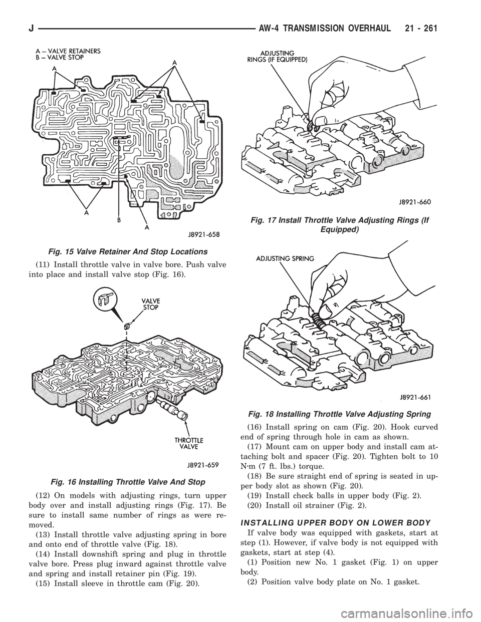
(11) Install throttle valve in valve bore. Push valve
into place and install valve stop (Fig. 16).
(12) On models with adjusting rings, turn upper
body over and install adjusting rings (Fig. 17). Be
sure to install same number of rings as were re-
moved.
(13) Install throttle valve adjusting spring in bore
and onto end of throttle valve (Fig. 18).
(14) Install downshift spring and plug in throttle
valve bore. Press plug inward against throttle valve
and spring and install retainer pin (Fig. 19).
(15) Install sleeve in throttle cam (Fig. 20).(16) Install spring on cam (Fig. 20). Hook curved
end of spring through hole in cam as shown.
(17) Mount cam on upper body and install cam at-
taching bolt and spacer (Fig. 20). Tighten bolt to 10
Nzm (7 ft. lbs.) torque.
(18) Be sure straight end of spring is seated in up-
per body slot as shown (Fig. 20).
(19) Install check balls in upper body (Fig. 2).
(20) Install oil strainer (Fig. 2).
INSTALLING UPPER BODY ON LOWER BODY
If valve body was equipped with gaskets, start at
step (1). However, if valve body is not equipped with
gaskets, start at step (4).
(1) Position new No. 1 gasket (Fig. 1) on upper
body.
(2) Position valve body plate on No. 1 gasket.
Fig. 15 Valve Retainer And Stop Locations
Fig. 16 Installing Throttle Valve And Stop
Fig. 17 Install Throttle Valve Adjusting Rings (If
Equipped)
Fig. 18 Installing Throttle Valve Adjusting Spring
JAW-4 TRANSMISSION OVERHAUL 21 - 261
Page 1639 of 2198
(3) Position new No. 2 gasket (Fig. 2) on valve
body plate and align gaskets and plate using bolt
holes as guides.
(4) Install valve body bolts.Three different
length bolts are used. Refer to the Figure 3 for
bolt locations. Chart symbols indicate bolt loca-
tion and length in millimeters.
(5) Tighten valve body bolts to 6.4 Nzm (56 in. lbs.)
torque.
Fig. 19 Installing Downshift Plug
Fig. 20 Installing Throttle Cam
Fig. 1 Valve Body Gasket No. 1
Fig. 2 Valve Body Gasket No. 2
Fig. 3 Valve Body Bolt Location/Size
21 - 262 AW-4 TRANSMISSION OVERHAULJ