1995 JEEP CHEROKEE trailer
[x] Cancel search: trailerPage 960 of 2198
TRAILER TOW
TRAILER TOW
The factory installed trailer tow system in this ve-
hicle uses three relays and a circuit breaker along
with the trailer tow wiring connector located below
the rear bumper.
Battery voltage for the trailer tow circuit breaker
and relays is supplied on circuit A11. This circuit is
HOT at all times and connects to the power accessory
tap in the fuse block. An in line 10 amp circuit pro-
tected breaker protects circuit A11 and the trailer
tow circuits. The trailer tow circuit breaker is located
in the left rear quarter panel.
STOP LAMP RELAY
Power for the coil side of the stop lamp relay is
supplied by circuit L50. This circuit connects to the
stop lamps. Ground for the coil side is supplied on
circuit Z1.
When the operator depresses the brake pedal, volt-
age flows through the coil of the relay to ground
causing the contacts in the relay to close connecting
circuits A11 and 95.
Circuit 95 connects to the left and right turn signal
relays. Voltage flows through the closed contacts in
the relays to the trailer tow connector.
RIGHT TURN RELAY
Power for the coil side of the right turn relay is
supplied by circuit L60. This circuit connects to the
right side turn signal lamps. Ground for the coil side
of the relay is supplied on circuit Z1.
When the operator turns the right turn signal ON,
power flows through the coil in the relay to ground
causing the contacts in the relay to switch from there
normally CLOSED position to connect circuits 94 and
L60.
Circuit 94 is the feed for the contact side of the re-
lay. Circuit L60 connects from the relay to the trailer
tow connector.
Circuit 94 is fed power through the normally
CLOSED side of the stop lamp relay and circuit A11.
The A11 circuit is HOT at all times and protected by
a 10 amp circuit breaker located in the left rear
quarter panel.
LEFT TURN RELAY
Power for the coil side of the left turn relay is sup-
plied by circuit L61. This circuit connects to the left
side turn signal lamps. Ground for the coil side of the
relay is supplied on circuit Z1.
When the operator turns the left turn signal ON,
power flows through the coil in the relay to ground
causing the contacts in the relay to switch from there
normally CLOSED position to connect circuits 94 and
L61.
Circuit 94 is the feed for the contact side of the re-
lay. Circuit L61 connects from the relay to the trailer
tow connector.
Circuit 94 is fed power through the normally
CLOSED side of the stop lamp relay and circuit A11.
The A11 circuit is HOT at all times and protected by
a 10 amp circuit breaker located in the right rear
quarter panel.
HELPFUL INFORMATION
²Check the In-Line circuit breaker
DIAGRAM INDEX
Component Page
Circuit Breaker (In-Line)....................8W-54-4
Electric Brake Provision....................8W-54-2
Fuse 1 (Fuse Block).......................8W-54-4
Fuse 3 (PDC)...........................8W-54-4
Left Turn Signal Relay.....................8W-54-3
Left Back-Up Lamp.......................8W-54-2
Left Side Marker Lamp.....................8W-54-2
Left Tail/Stop Lamp.......................8W-54-2
Left Turn Signal Lamp.....................8W-54-2
Right Turn Signal Relay....................8W-54-3
Stop Lamp Relay.........................8W-54-3
Trailer Tow Connector......................8W-54-2
J8W-54 TRAILER TOWÐXJ-RHD 8W - 54 - 1
Page 1079 of 2198
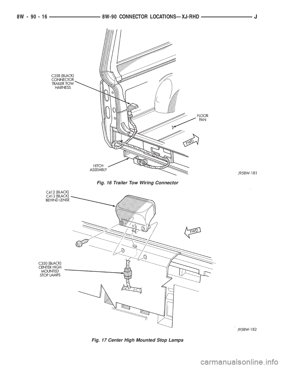
Fig. 16 Trailer Tow Wiring Connector
Fig. 17 Center High Mounted Stop Lamps
8W - 90 - 16 8W-90 CONNECTOR LOCATIONSÐXJ-RHDJ
Page 1083 of 2198
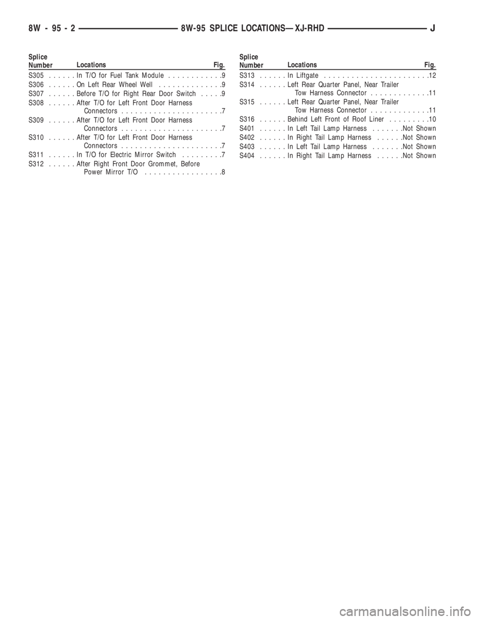
Splice
NumberLocations Fig.
S305......InT/OforFuel Tank Module............9
S306......OnLeft Rear Wheel Well..............9
S307......Before T/O for Right Rear Door Switch.....9
S308......After T/O for Left Front Door Harness
Connectors......................7
S309......After T/O for Left Front Door Harness
Connectors......................7
S310......After T/O for Left Front Door Harness
Connectors......................7
S311......InT/OforElectric Mirror Switch.........7
S312......After Right Front Door Grommet, Before
Power Mirror T/O.................8Splice
NumberLocations Fig.
S313......InLiftgate.......................12
S314......Left Rear Quarter Panel, Near Trailer
Tow Harness Connector.............11
S315......Left Rear Quarter Panel, Near Trailer
Tow Harness Connector.............11
S316......Behind Left Front of Roof Liner.........10
S401......InLeft Tail Lamp Harness.......Not Shown
S402......InRight Tail Lamp Harness......Not Shown
S403......InLeft Tail Lamp Harness.......Not Shown
S404......InRight Tail Lamp Harness......Not Shown
8W - 95 - 2 8W-95 SPLICE LOCATIONSÐXJ-RHDJ
Page 1090 of 2198
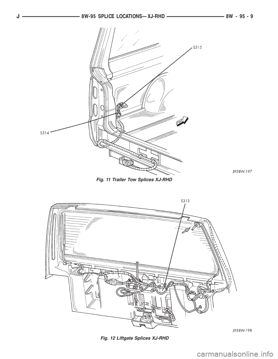
Fig. 11 Trailer Tow Splices XJ-RHD
Fig. 12 Liftgate Splices XJ-RHD
J8W-95 SPLICE LOCATIONSÐXJ-RHD 8W - 95 - 9
Page 1200 of 2198
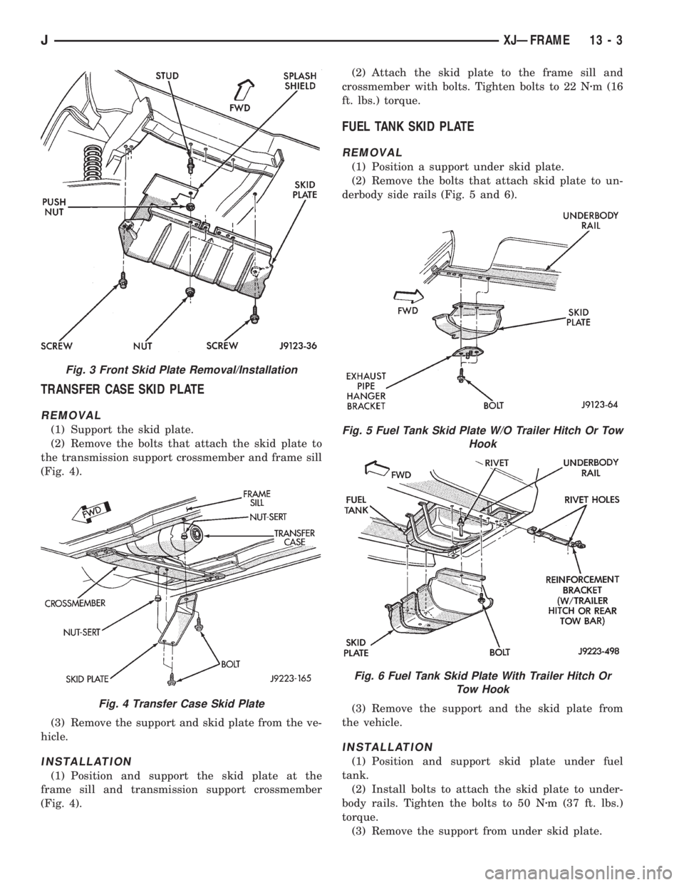
TRANSFER CASE SKID PLATE
REMOVAL
(1) Support the skid plate.
(2) Remove the bolts that attach the skid plate to
the transmission support crossmember and frame sill
(Fig. 4).
(3) Remove the support and skid plate from the ve-
hicle.
INSTALLATION
(1) Position and support the skid plate at the
frame sill and transmission support crossmember
(Fig. 4).(2) Attach the skid plate to the frame sill and
crossmember with bolts. Tighten bolts to 22 Nzm (16
ft. lbs.) torque.
FUEL TANK SKID PLATE
REMOVAL
(1) Position a support under skid plate.
(2) Remove the bolts that attach skid plate to un-
derbody side rails (Fig. 5 and 6).
(3) Remove the support and the skid plate from
the vehicle.
INSTALLATION
(1) Position and support skid plate under fuel
tank.
(2) Install bolts to attach the skid plate to under-
body rails. Tighten the bolts to 50 Nzm (37 ft. lbs.)
torque.
(3) Remove the support from under skid plate.
Fig. 3 Front Skid Plate Removal/Installation
Fig. 4 Transfer Case Skid Plate
Fig. 5 Fuel Tank Skid Plate W/O Trailer Hitch Or Tow
Hook
Fig. 6 Fuel Tank Skid Plate With Trailer Hitch Or
Tow Hook
JXJÐFRAME 13 - 3
Page 1205 of 2198
(10) Remove the support bracket from the bumper
rail.
INSTALLATION
(1) Install the bumper guard and bumper support
bracket on the bumper rail. Tighten the retaining
hardware in the sequence indicated in Figure 7.
Tighten locknuts to 20 Nzm (15 ft. lbs.) torque.
Tighten bolts to 56 Nzm (41 ft. lbs.) torque.
(2) If not equipped with bumper guards, install the
bumper support bracket on the bumper rail. Tighten
bolts to 56 Nzm (41 ft. lbs.) torque.
(3) Position the tow hook at the support bracket.
Install the bolts and nuts that attach tow hook to the
bumper support bracket. Tighten nuts to 100 Nzm (74
ft. lbs.) torque.
(4) Position and support the bumper at the front of
the vehicle.
(5) Attach the bumper support brackets to the
right and left sillmembers and reinforcement brack-
ets. Tighten screws and bolts to 56 Nzm (41 ft. lbs.)
torque.
(6) Install the Torx-head bolts and locknuts that
attach the tow hook straps to the underbody sillmem-
ber. Tighten locknuts to 30 Nzm (22 ft. lbs.) torque.
Install the steering gear skid plate and screws
after the left tow hook strap has been installed.
(7) Connect the fog lamp wire harness connectors.
Connect the vacuum reservoir tube harness connec-
tors.
(8) Remove the bumper support.
REAR BUMPER
REMOVAL
(1) For vehicles equipped with a trailer hitch, re-
move the hitch before removing the bumper. If neces-
sary, refer to the removal procedure within Group 23,
Body Components.
(2) Raise and support the rear of the vehicle.
(3) Support the bumper.
(4) Remove the bolts that attach the bumper sup-
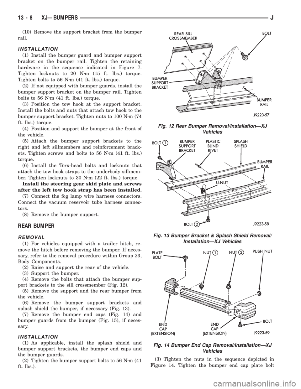
port brackets to the sill crossmember (Fig. 12).
(5) Remove the support and the rear bumper from
the vehicle.
(6) Remove the bumper support brackets and
splash shield the bumper, if necessary (Fig. 13).
(7) Remove the bumper end caps (Fig. 14) and
bumper guards from the bumper (Fig. 15), if neces-
sary.
INSTALLATION
(1) As applicable, install the splash shield and
bumper support brackets, the bumper end caps and
the bumper guards.
(2) Tighten the bumper support bolts to 56 Nzm (41
ft. lbs.).(3) Tighten the nuts in the sequence depicted in
Figure 14. Tighten the bumper end cap plate bolt
Fig. 12 Rear Bumper Removal/InstallationÐXJ
Vehicles
Fig. 13 Bumper Bracket & Splash Shield Removal/
InstallationÐXJ Vehicles
Fig. 14 Bumper End Cap Removal/InstallationÐXJ
Vehicles
13 - 8 XJÐBUMPERSJ
Page 1206 of 2198
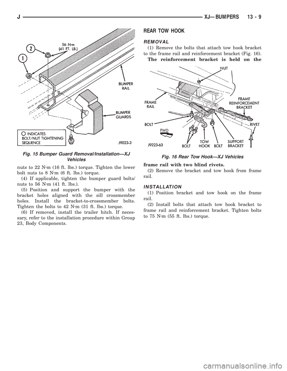
nuts to 22 Nzm (16 ft. lbs.) torque. Tighten the lower
bolt nuts to 8 Nzm (6 ft. lbs.) torque.
(4) If applicable, tighten the bumper guard bolts/
nuts to 56 Nzm (41 ft. lbs.).
(5) Position and support the bumper with the
bracket holes aligned with the sill crossmember
holes. Install the bracket-to-crossmember bolts.
Tighten the bolts to 42 Nzm (31 ft. lbs.) torque.
(6) If removed, install the trailer hitch. If neces-
sary, refer to the installation procedure within Group
23, Body Components.
REAR TOW HOOK
REMOVAL
(1) Remove the bolts that attach tow hook bracket
to the frame rail and reinforcement bracket (Fig. 16).
The reinforcement bracket is held on the
frame rail with two blind rivets.
(2) Remove the bracket and tow hook from frame
rail.
INSTALLATION
(1) Position bracket and tow hook on the frame
rail.
(2) Install bolts that attach tow hook bracket to
frame rail and reinforcement bracket. Tighten bolts
to 75 Nzm (55 ft. lbs.) torque.
Fig. 15 Bumper Guard Removal/InstallationÐXJ
VehiclesFig. 16 Rear Tow HookÐXJ Vehicles
JXJÐBUMPERS 13 - 9
Page 1447 of 2198
30RH/32RH TRANSMISSION DIAGNOSIS
INDEX
page page
Air Pressure Test......................... 74
Analyzing the Road Test.................... 71
Converter Housing Leak Diagnosis............ 75
Converter Stall Test........................ 74
Diagnosis Guides and Charts................ 77
Effects of Incorrect Fluid Level............... 71
Fluid Level Check......................... 70Gearshift Cable/Linkage Adjustment........... 71
General Information....................... 70
Hydraulic Pressure Test.................... 72
Preliminary Diagnosis...................... 70
Road Test............................... 71
Transmission Throttle Valve Cable Adjustment.... 71
GENERAL INFORMATION
Automatic transmission problems are generally a
result of:
²poor engine performance
²incorrect fluid level
²incorrect throttle valve cable adjustment
²incorrect band adjustment
²incorrect hydraulic control pressure adjustments
²hydraulic component malfunctions
²mechanical component malfunctions.
Begin diagnosis by checking the easily accessible
items such as fluid level, fluid condition and control
linkage adjustment. A road test will determine if fur-
ther diagnosis is necessary.
Procedures outlined in this section should be per-
formed in the following sequence to realize the most
accurate results:
²Preliminary diagnosis
²Check fluid level and condition
²Check control linkage Adjustment
²Road test
²Stall test
²Hydraulic pressure test
²Air pressure tests
²Leak test
²Analyze test results and consult diagnosis charts
PRELIMINARY DIAGNOSIS
Two basic procedures are required. One procedure
for vehicles that are driveable and an alternate pro-
cedure for disabled vehicles (will not back up or move
forward).
Vehicle Is Driveable
(1) Check fluid level and condition.
(2) Adjust throttle cable and gearshift linkage if
complaint was based on delayed, erratic, or harsh
shifts.
(3) Road test vehicle and note transmission operat-
ing characteristics.(4) Perform stall test if complaint is based on slug-
gish, low speed acceleration or abnormal throttle
opening needed to maintain normal speeds with
properly tuned engine.
(5) Perform hydraulic pressure tests.
(6) Perform air pressure test to check clutch-band
operation.
Vehicle Is Disabled
(1) Check fluid level and condition.
(2) Check for broken, disconnected throttle linkage.
(3) Check for cracked, leaking cooler lines, or loose,
missing pressure port plugs.
(4) Raise vehicle, start engine, shift transmission
into gear and note following:
(a) If propeller shafts turn but wheels do not,
problem is with differential or axle shafts.
(b) If propeller shafts do not turn and transmis-
sion is noisy, stop engine. Remove oil pan, and
check for debris. If pan is clear, remove transmis-
sion and check for damaged drive plate, converter,
oil pump or input shaft.
(c) If propeller shafts do not turn and transmis-
sion is not noisy, perform hydraulic pressure test to
determine if problem is a hydraulic or mechanical.
FLUID LEVEL CHECK
Transmission fluid level should be checked monthly
under normal operation. If the vehicle is used for
trailer towing or similar heavy load hauling, check
fluid level and condition weekly.
Fluid level is checked with the engine running at
curb idle speed, the transmission in Neutral and the
transmission fluid at normal operating temperature.
FLUID LEVEL CHECK PROCEDURE
(1) Transmission fluid must be at normal operating
temperature for accurate fluid level check. Drive ve-
hicle if necessary to bring fluid temperature up to
normal hot operating temperature of 82ÉC (180ÉF).
(2) Position vehicle on level surface. This is ex-
tremely important for accurate fluid level check.
(3) Start and run engine at curb idle speed.
21 - 70 30RH/32RH TRANSMISSION DIAGNOSISJ