1995 JEEP CHEROKEE tire pressure
[x] Cancel search: tire pressurePage 1489 of 2198
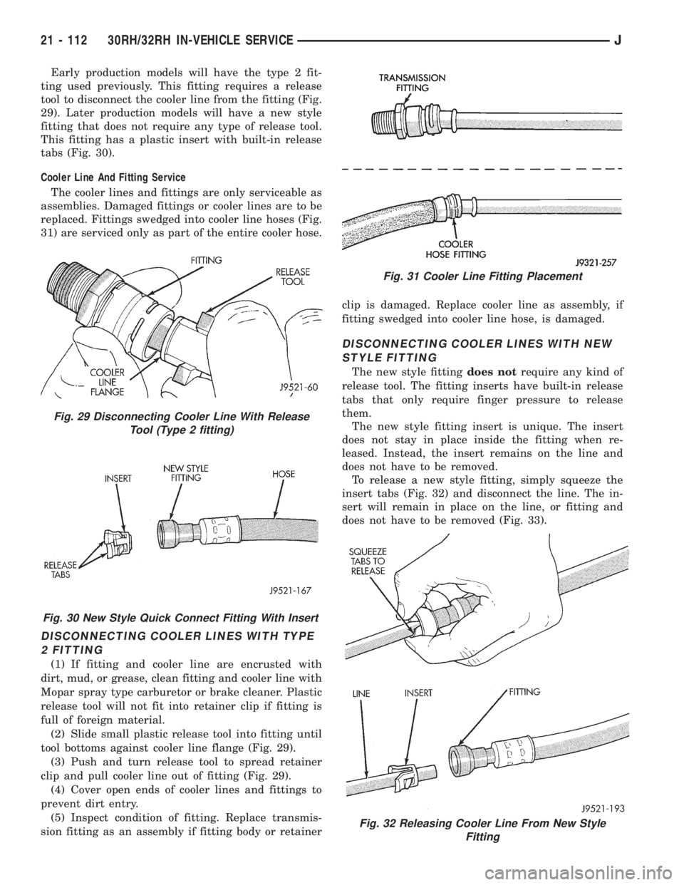
Early production models will have the type 2 fit-
ting used previously. This fitting requires a release
tool to disconnect the cooler line from the fitting (Fig.
29). Later production models will have a new style
fitting that does not require any type of release tool.
This fitting has a plastic insert with built-in release
tabs (Fig. 30).
Cooler Line And Fitting Service
The cooler lines and fittings are only serviceable as
assemblies. Damaged fittings or cooler lines are to be
replaced. Fittings swedged into cooler line hoses (Fig.
31) are serviced only as part of the entire cooler hose.
DISCONNECTING COOLER LINES WITH TYPE
2 FITTING
(1) If fitting and cooler line are encrusted with
dirt, mud, or grease, clean fitting and cooler line with
Mopar spray type carburetor or brake cleaner. Plastic
release tool will not fit into retainer clip if fitting is
full of foreign material.
(2) Slide small plastic release tool into fitting until
tool bottoms against cooler line flange (Fig. 29).
(3) Push and turn release tool to spread retainer
clip and pull cooler line out of fitting (Fig. 29).
(4) Cover open ends of cooler lines and fittings to
prevent dirt entry.
(5) Inspect condition of fitting. Replace transmis-
sion fitting as an assembly if fitting body or retainerclip is damaged. Replace cooler line as assembly, if
fitting swedged into cooler line hose, is damaged.
DISCONNECTING COOLER LINES WITH NEW
STYLE FITTING
The new style fittingdoes notrequire any kind of
release tool. The fitting inserts have built-in release
tabs that only require finger pressure to release
them.
The new style fitting insert is unique. The insert
does not stay in place inside the fitting when re-
leased. Instead, the insert remains on the line and
does not have to be removed.
To release a new style fitting, simply squeeze the
insert tabs (Fig. 32) and disconnect the line. The in-
sert will remain in place on the line, or fitting and
does not have to be removed (Fig. 33).
Fig. 30 New Style Quick Connect Fitting With Insert
Fig. 29 Disconnecting Cooler Line With Release
Tool (Type 2 fitting)
Fig. 31 Cooler Line Fitting Placement
Fig. 32 Releasing Cooler Line From New Style
Fitting
21 - 112 30RH/32RH IN-VEHICLE SERVICEJ
Page 1517 of 2198
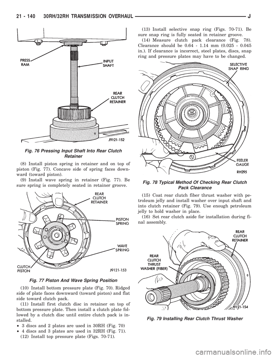
(8) Install piston spring in retainer and on top of
piston (Fig. 77). Concave side of spring faces down-
ward (toward piston).
(9) Install wave spring in retainer (Fig. 77). Be
sure spring is completely seated in retainer groove.
(10) Install bottom pressure plate (Fig. 70). Ridged
side of plate faces downward (toward piston) and flat
side toward clutch pack.
(11) Install first clutch disc in retainer on top of
bottom pressure plate. Then install a clutch plate fol-
lowed by a clutch disc until entire clutch pack is in-
stalled.
²3 discs and 2 plates are used in 30RH (Fig. 70)
²4 discs and 3 plates are used in 32RH (Fig. 71).
(12) Install top pressure plate (Figs. 70-71).(13) Install selective snap ring (Figs. 70-71). Be
sure snap ring is fully seated in retainer groove.
(14) Measure clutch pack clearance (Fig. 78).
Clearance should be 0.64 - 1.14 mm (0.025 - 0.045
in.). If clearance is incorrect, steel plates, discs, snap
ring and pressure plates may have to be changed.
(15) Coat rear clutch fiber thrust washer with pe-
troleum jelly and install washer over input shaft and
into clutch retainer (Fig. 79). Use enough petroleum
jelly to hold washer in place.
(16) Set rear clutch aside for installation during fi-
nal assembly.
Fig. 76 Pressing Input Shaft Into Rear Clutch
Retainer
Fig. 77 Piston And Wave Spring Position
Fig. 78 Typical Method Of Checking Rear Clutch
Pack Clearance
Fig. 79 Installing Rear Clutch Thrust Washer
21 - 140 30RH/32RH TRANSMISSION OVERHAULJ
Page 1722 of 2198
WHEELS AND TIRES
CONTENTS
page page
SPECIFICATIONS........................ 12
TIRES.................................. 1VEHICLE VIBRATION..................... 10
WHEELS................................ 6
TIRES
INDEX
page page
Cleaning of Tires.......................... 2
General Information........................ 1
Pressure Gauges.......................... 2
Repairing Leaks........................... 3
Replacement Tires......................... 2Rotation................................. 3
Tire Inflation Pressures...................... 2
Tire Noise or Vibration...................... 4
Tire Wear Patterns......................... 4
Tread Wear Indicators....................... 3
GENERAL INFORMATION
Tires are designed for each specific vehicle. They
provide the best overall performance for normal oper-
ation. The ride and handling characteristics match
the vehicle's requirements. With proper care they
will give excellent reliability, traction, skid resis-
tance, and tread life. These tires have specific load
carrying capacities. When correctly inflated, they will
operate properly.
Tires used in cool climates, and with light loads
will have a longer life than tires used in hot climates
with heavy loads. Abrasive road surfaces will acceler-
ate tire wear.
Driving habits have more effect on tire life than
any other factor. Careful drivers will obtain much
greater mileage than careless drivers.
Driving habits that shorten the life of any tire;
²Rapid acceleration and deceleration
²Severe application of brakes
²High-speed driving
²Taking turns at excessive speeds
²Striking curbs and other obstacles
It is very important to follow the tire rotation in-
terval
IDENTIFICATION
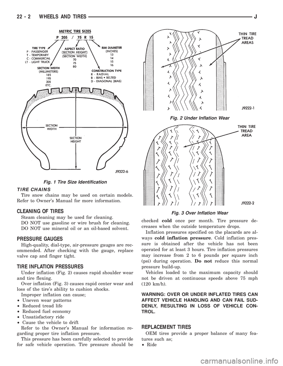
Tire type, size, aspect ratio and speed rating are
encoded in the letters and numbers imprinted on the
side wall of the tire. Refer to the chart to decipher
the tire identification code (Fig. 1).Performance tires will have a speed rating letter
after the aspect ratio number. The speed rating is not
always printed on the tire sidewall. The letterSin-
dicates that the tire is speed rated up to 112 mph.
²Qup to 100 mph
²Tup to 118 mph
²Uup to 124 mph
²Hup to 130 mph
²Vup to 149 mph
²Zmore than 149 mph (consult the tire manufac-
turer for the specific speed rating)
An All Season type tire will have eitherM+S,M
&SorMÐS(indicating mud and snow traction) im-
printed on the side wall.
RADIAL-PLY TIRES
Radial-ply tires improve handling, tread life, ride
quality and decrease rolling resistance.
Radial-ply tires must always be used in sets of
four. Under no circumstances should they be used on
the front only. They may be mixed with temporary
spare tires when necessary, but reduced speeds are
recommended.
Radial-ply tires have the same load-carrying capac-
ity as other types of tires of the same size. They use
the same recommended inflation pressures.
SPARE TIRE (TEMPORARY)
The compact spare tire is designed for emergency
use only. The original tire should be repaired and re-
installed at the first opportunity. Refer to Owner's
Manual for complete details.
JWHEELS AND TIRES 22 - 1
Page 1723 of 2198
TIRE CHAINS
Tire snow chains may be used on certain models.
Refer to Owner's Manual for more information.
CLEANING OF TIRES
Steam cleaning may be used for cleaning.
DO NOT use gasoline or wire brush for cleaning.
DO NOT use mineral oil or an oil-based solvent.
PRESSURE GAUGES
High-quality, dial-type, air-pressure gauges are rec-
ommended. After checking with the gauge, replace
valve cap and finger tight.
TIRE INFLATION PRESSURES
Under inflation (Fig. 2) causes rapid shoulder wear
and tire flexing.
Over inflation (Fig. 3) causes rapid center wear and
loss of the tire's ability to cushion shocks.
Improper inflation can cause;
²Uneven wear patterns
²Reduced tread life
²Reduced fuel economy
²Unsatisfactory ride
²Cause the vehicle to drift
Refer to the Owner's Manual for information re-
garding proper tire inflation pressure.
This pressure has been carefully selected to provide
for safe vehicle operation. Tire pressure should becheckedcoldonce per month. Tire pressure de-
creases when the outside temperature drops.
Inflation pressures specified on the placards are al-
wayscold inflation pressure. Cold inflation pres-
sure is obtained after the vehicle has not been
operated for at least 3 hours. Tire inflation pressures
may increase from 2 to 6 pounds per square inch
(psi) during operation.Do notreduce this normal
pressure build-up.
Vehicles loaded to the maximum capacity should
not be driven at continuous speeds above 75 mph
(120 km/h).
WARNING: OVER OR UNDER INFLATED TIRES CAN
AFFECT VEHICLE HANDLING AND CAN FAIL SUD-
DENLY, RESULTING IN LOSS OF VEHICLE CON-
TROL.
REPLACEMENT TIRES
OEM tires provide a proper balance of many fea-
tures such as;
²Ride
Fig. 1 Tire Size Identification
Fig. 2 Under Inflation Wear
Fig. 3 Over Inflation Wear
22 - 2 WHEELS AND TIRESJ
Page 1881 of 2198
CAUTION: Be prepared to install the windshield
glass immediately after applying the adhesive. The
adhesive begins to cure within 10-15 minutes.
(12) Align the windshield with the grease pencil
marks (or the tape strips) and position windshield on
frame flanges.
(13) Force the windshield glass inward just enough
to wet-out and set urethane. Use care to avoid exces-
sive squeeze-out of adhesive.
(14) Water test the windshield with a cold water
spray after installation. Do not direct high pressure
streams of water directly at the urethane. Use a
moderate spray only. If any leaks are detected, apply
urethane as necessary.
(15) Install the windshield reveal molding and (if
used) remove the masking tape from the inner sur-
face of the glass.
(16) Install all removed components and clean the
vehicle. If necessary, refer to the applicable installa-
tion procedures.
(17) Open windows and liftgate to prevent pres-
sure build-up while the urethane is curing.
(18) Install the rearview mirror on the bracket and
tighten the mirror setscrew with 2 Nzm (15 in-lbs)
torque.
INSTALLATIONÐEXTENDED METHOD
Normally, after a windshield is installed, the rear-
view mirror bracket also requires installation.Do
not install the bracket until after the wind-
shield installation is completed.
(1) Remove all of the original urethane from all the
frame pinchweld flanges. Use an electric hot knife
and a plow-type knife blade to remove the adhesive.
(2) Inspect and repair the windshield frame and
the pinchweld flanges as necessary.
(3) Inspect and replace the reveal molding if the
retainers are damaged.
(4) Prime the frame pinchweld flanges with a ure-
thane base primer. However, if the flange is top-
coated with paint, prime the flanges with a paint
finish primer.This is important because ure-
thane adhesive will not adhere to all top coat
paints.
(5) Install the replacement interior trim molding
(Fig. 5) on the frame pinchweld flanges (Fig. 5).
(6) Install and inspect the fit of the windshield
glass on the pinchweld flanges according to the fol-
lowing instructions:
²Position the windshield glass on the flanges and
adjust the position until it is correctly aligned within
the windshield frame.
²Measure the gap between the frame and the glass
around the entire perimeter of the glass and the
flange.
²The gap should be at least 3 mm (1/8 in) but no
more than 6 mm (1/4 in) at any point around the pe-rimeter, and the flanges should be in complete con-
tact with the glass around the perimeter of the
frame.
(7) If the pinchweld flanges require repair, remove
the windshield glass and straighten, align, or repair
the flange(s) as necessary.
(8) Position the windshield on the flanges and in-
spect the windshield fit again. If the fit is acceptable,
mark windshield final position on the glass and the
frame. The marks (or masking tape) will be used for
installation alignment reference.
(9) If the replacement windshield glass does not
have blackout primer:
²Attach a 25-mm (1-in) wide masking tape band
around the interior side of the glass 16 mm (5/8 in)
from the edge of the glass (Fig. 6).
²Attach the tape only to the interior side of
the glass.
²Thoroughly mix and apply blackout primer to the
16 mm (5/8 in) surface area around the interior side
of the glass (Fig. 6).
²Allow the primer to dry for at least 10-12 minutes.
(10) Cut the urethane adhesive applicator nozzle
(Fig. 7).
(11) Apply a 3-mm (1/8-in) diameter bead of ure-
thane to the surface area.
CAUTION: Be prepared to install the windshield
glass immediately after applying the adhesive. The
adhesive begins to cure within 10-15 minutes.
(12) Align windshield with reference marks (or the
tape strips) and position it on the frame pinchweld
flanges.
(13) Force the windshield glass inward just enough
to wet-out and set urethane. Use care to avoid exces-
sive squeeze-out of adhesive.
(14) Water test the windshield with a cold water
spray after installation. Do not direct high pressure
streams of water directly at the urethane. Use a
moderate spray only. If any leaks are detected, apply
urethane as necessary.
(15) Install the windshield reveal molding and (if
used) remove the masking tape from the inner sur-
face of the glass.
(16) Install all the other previously removed com-
ponents and clean the vehicle. If necessary, refer to
the applicable installation procedures.
(17) Open windows and liftgate to prevent pres-
sure build-up while the urethane is curing.
(18) Install the rearview mirror on the bracket and
tighten the mirror setscrew to 2 Nzm (15 in-lbs)
torque.
23 - 148 STATIONARY GLASSÐYJJ
Page 1905 of 2198
oil until you are ready to use it. Install the cap im-
mediately after using. Store the oil only in a clean
moisture-free container.
Keep service tools and the work area clean. Con-
tamination of A/C system through careless work hab-
its must be avoided.
COOLING SYSTEM
To maintain the performance level of the heating/
air conditioning system, the engine cooling system
must be properly maintained.
The use of a bug screen is not recommended. Any
obstructions in front of the radiator or condenser can
reduce the performance of the A/C and cooling sys-
tem. If a bug screen is used it must be cleaned fre-
quently.
COOLANT PRECAUTIONS
WARNING: ANTIFREEZE IS AN ETHYLENE GLYCOL
BASE COOLANT AND IS HARMFUL IF SWAL-
LOWED OR INHALED. IF SWALLOWED, DRINK
TWO GLASSES OF WATER AND INDUCE VOMIT-
ING. IF INHALED, MOVE TO FRESH AIR AREA.
SEEK MEDICAL ATTENTION IMMEDIATELY.
WARNING: WASH SKIN AND CLOTHING THOR-
OUGHLY AFTER COMING IN CONTACT WITH ETH-
YLENE GLYCOL.
WARNING: KEEP OUT OF REACH OF CHILDREN
AND PETS.
WARNING: DO NOT OPEN A COOLING SYSTEM
WHEN THE ENGINE IS AT RUNNING TEMPERA-
TURE. PERSONAL INJURY CAN RESULT.WARNING: DO NOT STORE IN OPEN OR UN-
MARKED CONTAINERS.
WARNING: HOT ENGINE COOLANT CAN CAUSE
SEVERE BURNS. DO NOT OPEN THE RADIATOR
DRAIN COCK WHEN THE COOLING SYSTEM IS
HOT AND PRESSURIZED. ALLOW THE COOLANT
TO DECREASE TO ROOM TEMPERATURE BEFORE
STARTING REPAIR OPERATIONS.
The engine cooling system is designed to develop
internal pressure of 97 to 124 kPa (14 to 18 psi). Al-
low the vehicle 15 minutes to cool down (or until a
safe temperature and pressure are attained) before
opening the cooling system. Refer to Group 7, Cooling
System.REFRIGERANT HOSES/TUBES PRECAUTIONS
Kinks or sharp bends in the refrigerant tubing or
hoses will reduce the capacity of the entire system.
High pressures are produced in the system when it is
operating. Extreme care must be exercised to make
sure that all connections are pressure tight. Dirt and
moisture can enter the system when it is opened for
repair.
A good rule for the flexible hose lines is to keep the
radius of all bends at least 10 times the diameter of
the hose. Sharp bends will reduce the flow of refrig-
erant. The flexible hose lines should be routed so
they are at least 80 mm (3 inches) from the exhaust
manifold. It is a good practice to inspect all flexible
hose lines at least once a year to make sure they are
in good condition and properly routed.
24 - 10 HEATING AND AIR CONDITIONINGJ
Page 1949 of 2198
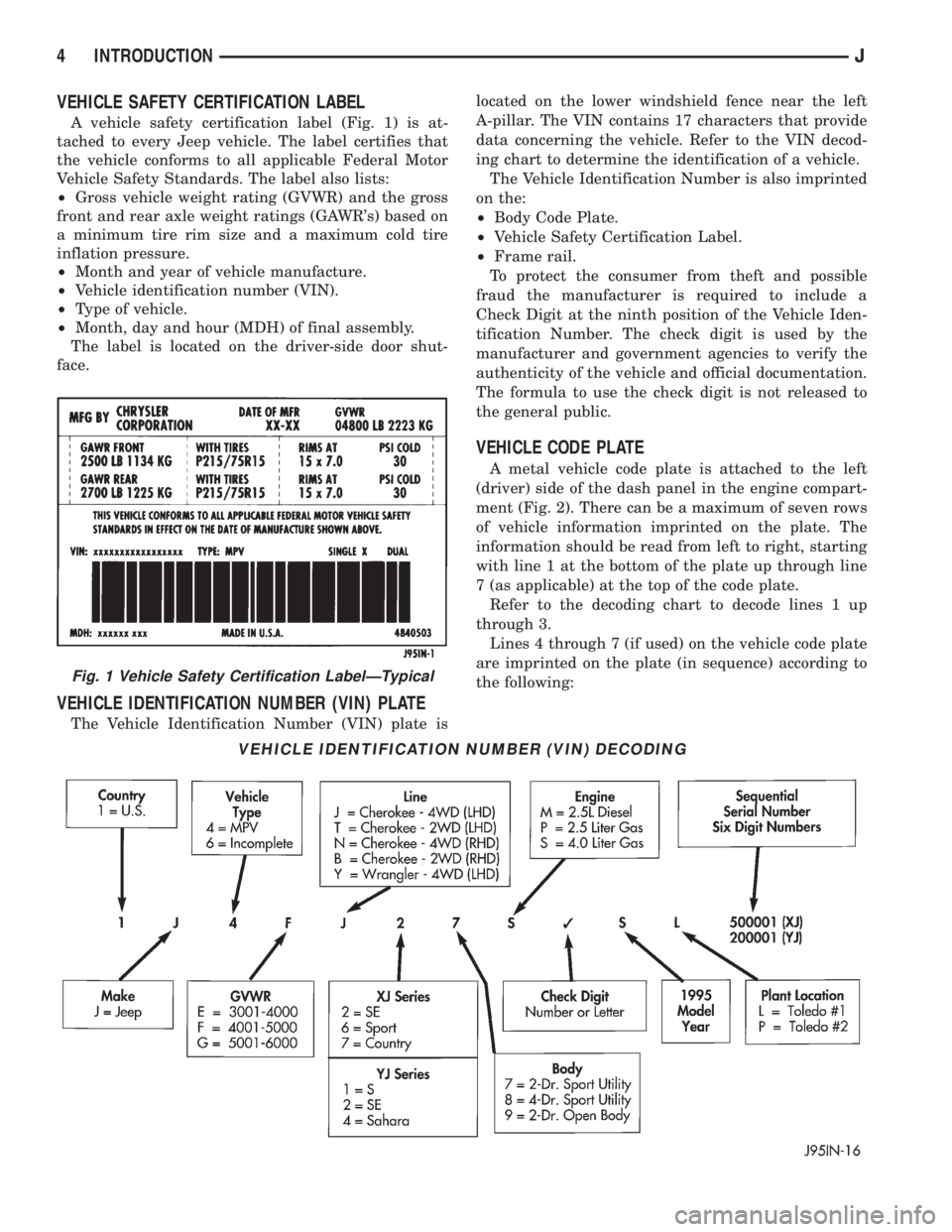
VEHICLE SAFETY CERTIFICATION LABEL
A vehicle safety certification label (Fig. 1) is at-
tached to every Jeep vehicle. The label certifies that
the vehicle conforms to all applicable Federal Motor
Vehicle Safety Standards. The label also lists:
²Gross vehicle weight rating (GVWR) and the gross
front and rear axle weight ratings (GAWR's) based on
a minimum tire rim size and a maximum cold tire
inflation pressure.
²Month and year of vehicle manufacture.
²Vehicle identification number (VIN).
²Type of vehicle.
²Month, day and hour (MDH) of final assembly.
The label is located on the driver-side door shut-
face.
VEHICLE IDENTIFICATION NUMBER (VIN) PLATE
The Vehicle Identification Number (VIN) plate islocated on the lower windshield fence near the left
A-pillar. The VIN contains 17 characters that provide
data concerning the vehicle. Refer to the VIN decod-
ing chart to determine the identification of a vehicle.
The Vehicle Identification Number is also imprinted
on the:
²Body Code Plate.
²Vehicle Safety Certification Label.
²Frame rail.
To protect the consumer from theft and possible
fraud the manufacturer is required to include a
Check Digit at the ninth position of the Vehicle Iden-
tification Number. The check digit is used by the
manufacturer and government agencies to verify the
authenticity of the vehicle and official documentation.
The formula to use the check digit is not released to
the general public.
VEHICLE CODE PLATE
A metal vehicle code plate is attached to the left
(driver) side of the dash panel in the engine compart-
ment (Fig. 2). There can be a maximum of seven rows
of vehicle information imprinted on the plate. The
information should be read from left to right, starting
with line 1 at the bottom of the plate up through line
7 (as applicable) at the top of the code plate.
Refer to the decoding chart to decode lines 1 up
through 3.
Lines 4 through 7 (if used) on the vehicle code plate
are imprinted on the plate (in sequence) according to
the following:
VEHICLE IDENTIFICATION NUMBER (VIN) DECODING
Fig. 1 Vehicle Safety Certification LabelÐTypical
4 INTRODUCTIONJ
Page 1965 of 2198
BUMPERÐXJ, LIFTGATE LICENSE PLATE
SCREW ANCHOR.....................23-65
BUMPERÐXJ, REAR SEATBACK LATCH
STRIKER...........................23-84
BUMPERS......................13-16,13-5
BUS, CCD; FUEL/IGNITION (XJ).......8W-30-5
BUSHING AND PISTON CLEARANCE,
AW-4 .............................21-339
BUSHING REPLACEMENT, AXLE......2-12,2-34
BUSHING REPLACEMENT, LEAF SPRING
EYE; FRONT SUSPENSION AND AXLE.....2-17
BUSHING REPLACEMENT, LEAF SPRING
EYE; REAR SUSPENSION AND AXLES . . . 3-5,3-7
BUSHINGS, CLUTCH AND BRAKE PEDAL . . . 0-22
BUZZER, COMBINATION; INTERIOR
LIGHTING (YJ)....................8W-44-1
BUZZER MODULE.................8U-1,8U-2
BUZZER MODULE SCHEMATIC - YJ.......8U-4
CABLE, ACCELERATOR PEDAL AND
THROTTLE.....................14-17,14-58
CABLE ADJUSTMENT, PARK INTERLOCK . 21-195
CABLE ADJUSTMENT, SHIFT...........21-195
CABLE ADJUSTMENT, TRANSMISSION
THROTTLE.........................21-194
CABLE ADJUSTMENT, TRANSMISSION
THROTTLE VALVE....................21-71
CABLE ADJUSTMENT (XJ), PARK
INTERLOCK........................21-101
CABLE ADJUSTMENT (XJ), SHIFT.......21-100
CABLE ADJUSTMENT (XJ/YJ), THROTTLE
VALVE..............................21-101
CABLE REMOVE/INSTALL, SERVO.......8H-10
CABLE REPLACEMENT, TRANSMISSION
THROTTLE.........................21-193
CABLE REPLACEMENT (XJ), PARKING
BRAKE REAR.........................5-67
CABLE REPLACEMENT (YJ), PARKING
BRAKE FRONT........................5-67
CABLE REPLACEMENT (YJ), PARKING
BRAKE REAR.........................5-68
CABLE REPLACEMENTÐXJ, LATCH
RELEASE...........................23-11
CABLE RESISTANCE, SPARK PLUG......8D-14
CABLE, SERVO.......................8H-1
CABLE, SPEEDOMETER.................0-33
CABLE TENSIONER ADJUSTMENT
(XJ/YJ), PARKING BRAKE...............5-69
CABLE TENSIONER REPLACEMENT (XJ),
PARKING BRAKE......................5-66
CABLE, THROTTLE...................14-17
CABLE/LINKAGE ADJUSTMENT,
GEARSHIFT.........................21-71
CABLES, DISTRIBUTOR CAP AND
ROTOR, IGNITION.....................0-20
CABLES, SPARK PLUG SECONDARY.....8D-14,
8D-24
CABLES, VENT DOOR CONTROL.........24-32
CALIBRATION, COMPASS...............8C-5
CALIPER ASSEMBLY...................5-50
CALIPER CLEANING AND INSPECTION.....5-50
CALIPER DISASSEMBLY................5-48
CALIPER INSTALLATION................5-51
CALIPER OPERATION AND WEAR
COMPENSATION......................5-45
CALIPER REMOVAL....................5-48
CAMSHAFT......................9-32,9-74
CAMSHAFT PIN REPLACEMENT......9-34,9-75
CAMSHAFT POSITION SENSOR; FUEL
SYSTEM............................14-60
CAMSHAFT POSITION SENSOR;
FUEL/IGNITION (XJ)................8W-30-3
CAMSHAFT POSITION SENSOR;
FUEL/IGNITION (YJ)................8W-30-3
CAMSHAFT POSITION SENSOR;
IGNITION SYSTEMS..............8D-17,8D-2
CAMSHAFT POSITION SENSOR;
FUEL/IGNITION (XJ-RHD)............8W-30-3
CAMSHAFT POSITION SENSOR TEST;
FUEL SYSTEM.......................14-46
CAMSHAFT POSITION SENSOR TEST;
IGNITION SYSTEMS
...................8D-6
CAMSHAFT POSITION SENSORÐPCM
INPUT
.............................14-22
(CANADA ONLY)ÐXJ, DAYTIME
RUNNING LIGHTS
....................8L-15
(CANADA ONLY)ÐYJ, DAYTIME
RUNNING LIGHTS
....................8L-30
CANISTER, EVAP
..................25-4,25-7CAP AND ROTOR, IGNITION CABLES,
DISTRIBUTOR........................0-20
CAP, DISTRIBUTOR....................8D-7
CAP, FUEL TANK FILLER TUBE;
EMISSION CONTROL SYSTEMS......25-4,25-7
CAP, FUEL TANK FILLER TUBE; FUEL
SYSTEM............................14-13
CAP, RADIATOR PRESSURE.............7-25
CAPACITIES, COOLING SYSTEM..........7-45
CAPACITIES, FLUID.....................0-3
CAPACITIES, FUEL TANK..........14-13,14-67
CAPACITY TEST, FUEL PUMP............14-7
CAR REPLACEMENT, PITMAN SHAFT
SEALSÐIN.........................19-23
CARDAN (CV), DOUBLE................16-11
CARDAN, SINGLE....................16-10
CARGO BARRIERÐXJ................23-101
CARGO LAMP AND DOME LAMP;
INTERIOR LIGHTING (XJ-RHD)........8W-44-1
CARGO LAMP, COURTESY LAMPS AND
DOME LAMP; INTERIOR LIGHTING (XJ) . 8W-44-1
CARGO LAMPÐXJ...................23-94
CARPET/MATÐXJ, FRONT.............23-99
CARPET/MATÐXJ, REAR.............23-100
CARPETÐYJ.......................23-156
CARPETS AND FLOOR MATSÐXJ.......23-99
CARRIERÐYJ, EXTERNAL SPARE/
WHEEL TIRE.......................23-133
CASE (4WD VEHICLES), TRANSFER........0-24
CASE ASSEMBLY, TRANSFER....21-294,21-319
CASE CHANGES, TRANSFER...........21-307
CASE CLEANING AND INSPECTION,
TRANSMISSION.....................21-125
CASE COVER OIL SEAL REPLACEMENT,
TIMING.........................9-30,9-73
CASE COVER, TIMING..............9-31,9-72
CASE DISASSEMBLY AND OVERHAUL,
TRANSFER...................21-289,21-310
CASE IDENTIFICATION, TRANSFER.....21-284,
21-307
CASE INSTALLATION, TRANSFER . 21-288,21-309
CASE LUBRICANT AND FILL LEVEL,
TRANSFER.........................21-284
CASE, NP231 TRANSFER.......21-283,21-305
CASE, NP242 TRANSFER.......21-307,21-331
CASE OVERHAUL, FIRST-REVERSE
BRAKE PISTON AND TRANSMISSION....21-247
CASE REMOVAL, TRANSFER.....21-287,21-309
CASE SKID PLATE, TRANSFER......13-15,13-3
CASE SPECIFICATIONS, TRANSMISSION/
TRANSFER.........................21-333
CATALYTIC CONVERTER............11-1,11-4
CATALYTIC CONVERTOR................25-1
CAUTIONS, AND WARNINGS, NOTES;
WIRING DIAGRAMSÐGENERAL
INFORMATION (XJ)...................8W-1
CCD BUS; FUEL/IGNITION (XJ)........8W-30-5
CENTER HIGH MOUNTED STOP LAMP
(CHMSL)ÐXJ.......................8L-12
CENTER HIGH MOUNTED STOP LAMP
(CHMSL)ÐYJ.......................8L-28
CERTIFICATION LABEL, VEHICLE SAFETY . Intro.-4
CHAIN AND SPROCKETS, TIMING....9-31,9-73
CHANGE AND FILTER REPLACEMENT,
ENGINE OIL
..........................0-16
CHANGE, LUBRICANT; FRONT
SUSPENSION AND AXLE
................2-23
CHANGE, LUBRICANT; REAR
SUSPENSION AND AXLES
...........3-13,3-31
CHANGE, REFILLING AFTER OVERHAUL
OR FLUID/FILTER
..............21-100,21-182
CHANGES AND PARTS
INTERCHANGEABILITY, TRANSMISSION
. . . 21-67
CHANGES, TRANSFER CASE
...........21-307
CHANNEL REPLACEMENTÐYJ, DOOR
FRAME GLASS
......................23-142
CHARGING, BATTERY
..................8A-7
CHARGING REFRIGERANT SYSTEM
......24-11
CHARGING SYSTEM; BATTERY/
STARTING/CHARGING SYSTEMS
DIAGNOSTICS
.......................8A-17
CHARGING SYSTEM; CHARGING
SYSTEM (XJ)
.....................8W-20-1
CHARGING SYSTEM; CHARGING
SYSTEM (XJ-RHD)
.................8W-20-1
CHARGING SYSTEM; CHARGING
SYSTEM (YJ)
.....................8W-20-1CHARGING SYSTEM INDICATOR LAMP;
INSTRUMENT CLUSTER (XJ).........8W-40-3
CHARGING SYSTEM SPECIFICATIONS....8A-23
CHARGING TIME TABLE, BATTERY........8A-8
CHART, MAIN BEARING FITTING......9-48,9-90
CHART, XJ PERFORMANCE
TEMPERATURE AND PRESSURE.........24-13
CHART, YJ PERFORMANCE
TEMPERATURE AND PRESSURE.........24-13
CHARTÐAX 15 MANUAL
TRANSMISSION, SELECTIVE SNAP
RING.............................21-334
CHARTS, BRAKELINE..................5-12
CHARTS, DIAGNOSIS GUIDES...........21-77
CHARTS, GEARTRAIN OPERATION AND
APPLICATION.......................21-169
CHARTS, INSPECTION AND DIAGNOSIS.....6-4
CHASSIS AND BODY COMPONENTS.......0-28
CHASSIS COMPONENT AND WHEEL
BEARING LUBRICANTS.................0-28
CHECK VALVE TEST, POWER BOOSTER.....5-9
CHECKING FLUID LEVEL AND
CONDITION........................21-182
CHECKS, PRELIMINARY.................7-5
CHIME/BUZZER MODULE; INTERIOR
LIGHTING (XJ)....................8W-44-2
CHIME/BUZZER MODULE; INTERIOR
LIGHTING (XJ-RHD)................8W-44-2
CHMSL LAMPS, STOP LAMPS; REAR
LIGHTING (XJ)....................8W-51-1
CHMSL LAMPS, STOP LAMPS; REAR
LIGHTING (XJ-RHD)................8W-51-1
CHMSL LAMPS, STOP LAMPS; REAR
LIGHTING (YJ)....................8W-51-1
(CHMSL)ÐXJ, CENTER HIGH MOUNTED
STOP LAMP.........................8L-12
(CHMSL)ÐYJ, CENTER HIGH MOUNTED
STOP LAMP.........................8L-28
CIGAR LIGHTER; HORN/CIGAR LIGHTER . . . 8E-1
CIGAR LIGHTER; HORN/CIGAR LIGHTER
(YJ).............................8W-41-1
CIGAR LIGHTER; INSTRUMENT CLUSTER
(XJ).............................8W-40-1
CIRCUIT IDENTIFICATION; WIRING
DIAGRAMSÐGENERAL INFORMATION
(XJ)...............................8W-1
CIRCUIT REMOVE/INSTALL, PRINTED....8E-19,
8E-40
CIRCUIT SENSEÐPCM INPUT, IGNITION . . 14-23
CIRCUIT VOLTAGE, OPEN...............8A-6
CLAMPS, FUEL TUBES/LINES/HOSES . 14-62,14-9
CLASSIFICATION OF LUBRICANTS.........0-2
CLASSIFICATIONS AND RATINGS,
BATTERY...........................8A-23
CLEANER, AIR.......................14-29
CLEANER ELEMENT, AIR; EMISSION
CONTROL SYSTEMS...................25-7
CLEANER ELEMENT, AIR; FUEL SYSTEM . . 14-59
CLEANER ELEMENT, AIR; LUBRICATION
AND MAINTENANCE...................0-18
CLEANER HOUSING, AIR...............14-58
CLEANING AND INSPECTION, CALIPER....5-50
CLEANING AND INSPECTION, GEAR......19-42
CLEANING AND INSPECTION,
TRANSMISSION CASE................21-125
CLEANING OF TIRES...................22-2
CLEANING/INSPECTION; FRONT
SUSPENSION AND AXLE
................2-37
CLEANING/INSPECTION; REAR
SUSPENSION AND AXLES
...............3-20
CLEANING/REVERSE FLUSHING,
COOLING SYSTEM
....................7-22
CLEARANCE AND RAMP ANGLE,
GROUND
............................0-11
CLEARANCE, AW-4 BUSHING AND
PISTON
...........................21-339
CLOCKSPRING
.......................19-51
CLUSTER AND GAUGE HOUSINGSÐYJ,
INSTRUMENT
......................23-151
CLUSTER ASSEMBLY REMOVE/INSTALL
. . 8E-17,
8E-35
CLUSTER BEZELÐXJ, INSTRUMENT
.....23-80
CLUSTER BEZELÐYJ, INSTRUMENT
....23-151
CLUSTER CONNECTORS (RHD)
.........8E-11
CLUSTER, GAUGE PACKAGE
.......8E-31,8E-43
CLUSTER GROUND; INSTRUMENT
CLUSTER (XJ)
.....................8W-40-3
4 INDEXJ
Description Group-Page Description Group-Page Description Group-Page