1995 JEEP CHEROKEE remove seats
[x] Cancel search: remove seatsPage 1814 of 2198
INSTALLATION
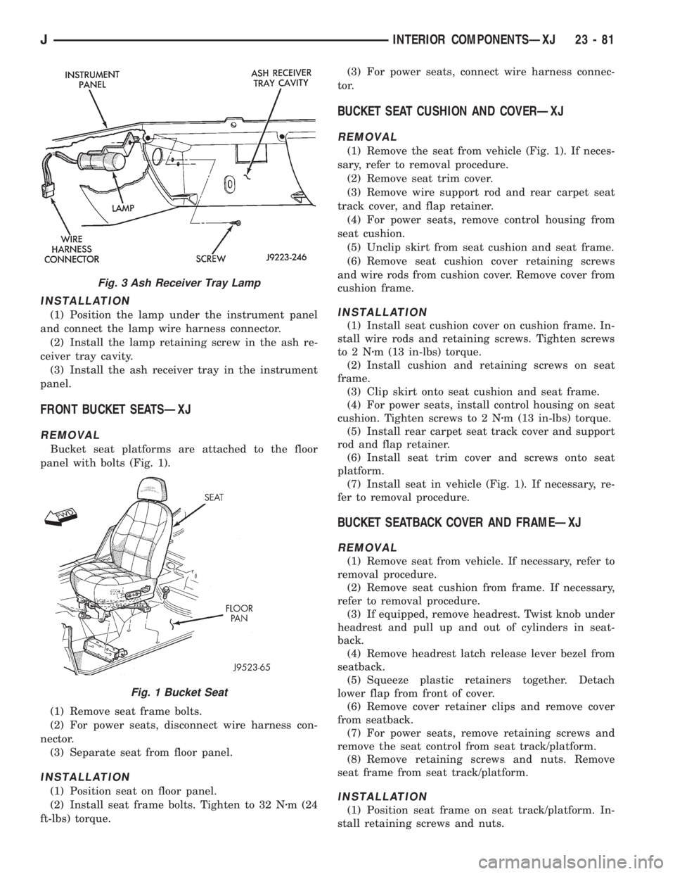
(1) Position the lamp under the instrument panel
and connect the lamp wire harness connector.
(2) Install the lamp retaining screw in the ash re-
ceiver tray cavity.
(3) Install the ash receiver tray in the instrument
panel.
FRONT BUCKET SEATSÐXJ
REMOVAL
Bucket seat platforms are attached to the floor
panel with bolts (Fig. 1).
(1) Remove seat frame bolts.
(2) For power seats, disconnect wire harness con-
nector.
(3) Separate seat from floor panel.
INSTALLATION
(1) Position seat on floor panel.
(2) Install seat frame bolts. Tighten to 32 Nzm (24
ft-lbs) torque.(3) For power seats, connect wire harness connec-
tor.
BUCKET SEAT CUSHION AND COVERÐXJ
REMOVAL
(1) Remove the seat from vehicle (Fig. 1). If neces-
sary, refer to removal procedure.
(2) Remove seat trim cover.
(3) Remove wire support rod and rear carpet seat
track cover, and flap retainer.
(4) For power seats, remove control housing from
seat cushion.
(5) Unclip skirt from seat cushion and seat frame.
(6) Remove seat cushion cover retaining screws
and wire rods from cushion cover. Remove cover from
cushion frame.
INSTALLATION
(1) Install seat cushion cover on cushion frame. In-
stall wire rods and retaining screws. Tighten screws
to2Nzm (13 in-lbs) torque.
(2) Install cushion and retaining screws on seat
frame.
(3) Clip skirt onto seat cushion and seat frame.
(4) For power seats, install control housing on seat
cushion. Tighten screws to 2 Nzm (13 in-lbs) torque.
(5) Install rear carpet seat track cover and support
rod and flap retainer.
(6) Install seat trim cover and screws onto seat
platform.
(7) Install seat in vehicle (Fig. 1). If necessary, re-
fer to removal procedure.
BUCKET SEATBACK COVER AND FRAMEÐXJ
REMOVAL
(1) Remove seat from vehicle. If necessary, refer to
removal procedure.
(2) Remove seat cushion from frame. If necessary,
refer to removal procedure.
(3) If equipped, remove headrest. Twist knob under
headrest and pull up and out of cylinders in seat-
back.
(4) Remove headrest latch release lever bezel from
seatback.
(5) Squeeze plastic retainers together. Detach
lower flap from front of cover.
(6) Remove cover retainer clips and remove cover
from seatback.
(7) For power seats, remove retaining screws and
remove the seat control from seat track/platform.
(8) Remove retaining screws and nuts. Remove
seat frame from seat track/platform.
INSTALLATION
(1) Position seat frame on seat track/platform. In-
stall retaining screws and nuts.
Fig. 3 Ash Receiver Tray Lamp
Fig. 1 Bucket Seat
JINTERIOR COMPONENTSÐXJ 23 - 81
Page 1815 of 2198
(2) For power seats, position seat control on seat
track/platform. Install retaining screws. Tighten
screws securely.
(3) Position cover on seatback. Install cover re-
tainer clips.
(4) Attach cover bottom elastic band or attach Vel-
cro flap to front of cover.
(5) Install seatback insert.
(6) Install headrest latch release lever bezel.
(7) Install headrest by pushing it down into seat-
back cylinders.
(8) Install cushion on frame. If necessary, refer to
installation procedure.
(9) Install seat in the vehicle. If necessary, refer to
the installation procedure.
(10) For power seats, test seat operation.
BUCKET SEAT PLATFORMÐXJ
REPLACEMENT
Bucket seat platforms are not repairable. If the
seat platform is damaged, replace platform as a unit.
REAR SEAT CUSHIONÐXJ
REMOVAL
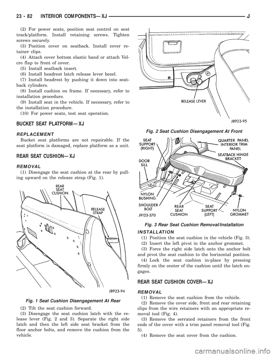
(1) Disengage the seat cushion at the rear by pull-
ing upward on the release strap (Fig. 1).
(2) Tilt the seat cushion forward.
(3) Disengage the seat cushion latch with the re-
lease lever (Fig. 2 and 3). Separate the right side
latch and then the left side seat bracket from the
floor anchor bolts, and remove the cushion from the
vehicle.
INSTALLATION
(1) Position the seat cushion in the vehicle (Fig. 3).
(2) Insert the left pivot in the anchor grommet.
(3) Force the right side latch onto the anchor bolt
and pivot the seat cushion to the horizontal position.
(4) Lock the seat cushion in-place by pressing
firmly on the center of the cushion until the latch en-
gages.
REAR SEAT CUSHION COVERÐXJ
REMOVAL
(1) Remove the seat cushion from the vehicle.
(2) Remove the cover side, front and rear retaining
clips from the wire retainers with an appropriate re-
moval tool (Fig. 4).
(3) Remove the serrated retainers from the front
ends of the cover with a trim panel removal tool (Fig.
5).
(4) Remove the seat cover from the cushion.Fig. 1 Seat Cushion Disengagement At Rear
Fig. 2 Seat Cushion Disengagement At Front
Fig. 3 Rear Seat Cushion Removal/Installation
23 - 82 INTERIOR COMPONENTSÐXJJ
Page 1823 of 2198
(3) Remove the assist handle from the trim mold-
ing.
INSTALLATION
(1) Position the handle on the trim molding and in-
stall the retaining screws. Tighten the retaining
screws to 3 Nzm (22 in-lbs) torque.
(2) Install the covers over the retaining screws.
FRONT SHOULDER BELT/BUCKLEÐXJ
REMOVAL
(1) Slide the front seats all the way forward for ac-
cess to the belt anchor bolt.
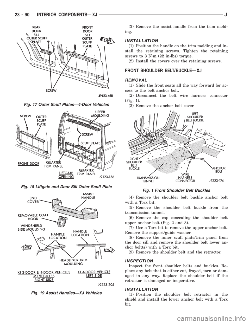
(2) Disconnect the belt wire harness connector
(Fig. 1).
(3) Remove the anchor bolt cover.
(4) Remove the shoulder belt buckle anchor bolt
with a Torx bit.
(5) Remove the shoulder belt buckle from the
transmission tunnel.
(6) Remove the cap concealing the shoulder belt
upper anchor bolt (Fig. 2 and 3).
(7) Use a Torx bit to remove the upper anchor bolt.
Remove the support/guide washer.
(8) Remove the inner scuff plate/trim panel from
the door sill and remove the shoulder belt lower an-
chor bolt(s) with a Torx bit.
(9) Remove the shoulder belt and the retractor.
INSPECTION
Inspect the front shoulder belts and buckles. Re-
place any belt that is either cut, frayed, torn or dam-
aged in any way. Replace the shoulder belt if the
retractor is damaged or inoperative.
INSTALLATION
(1) Position the shoulder belt retractor in the
shield and install the lower anchor bolt with a Torx
bit.
Fig. 17 Outer Scuff PlatesÐ4-Door Vehicles
Fig. 18 Liftgate and Door Sill Outer Scuff Plate
Fig. 19 Assist HandlesÐXJ Vehicles
Fig. 1 Front Shoulder Belt Buckles
23 - 90 INTERIOR COMPONENTSÐXJJ
Page 1832 of 2198
CARPETS AND FLOOR MATSÐXJ
The carpets/mats are retained around the perime-
ter of the floor panel by the interior trim moldings
and trim panels. To remove a carpet/mat, all of the
retaining trim moldings and panels must be removed
along with all the interfering components (as appli-
cable):
²Seat(s).
²Parking brake lever cover.
²Floor console.
²Transmission and transfer case (if equipped) floor
shift cover/boot.
If necessary, refer to the applicable removal proce-
dure(s) within this manual.
FRONT CARPET/MATÐXJ
REMOVAL
(1) Remove the door sill inner scuff plates.
(2) Remove the front and rear seats (as applicable).
(3) As necessary, remove the trim panels and mold-
ings.
(4) Remove all other interfering components.
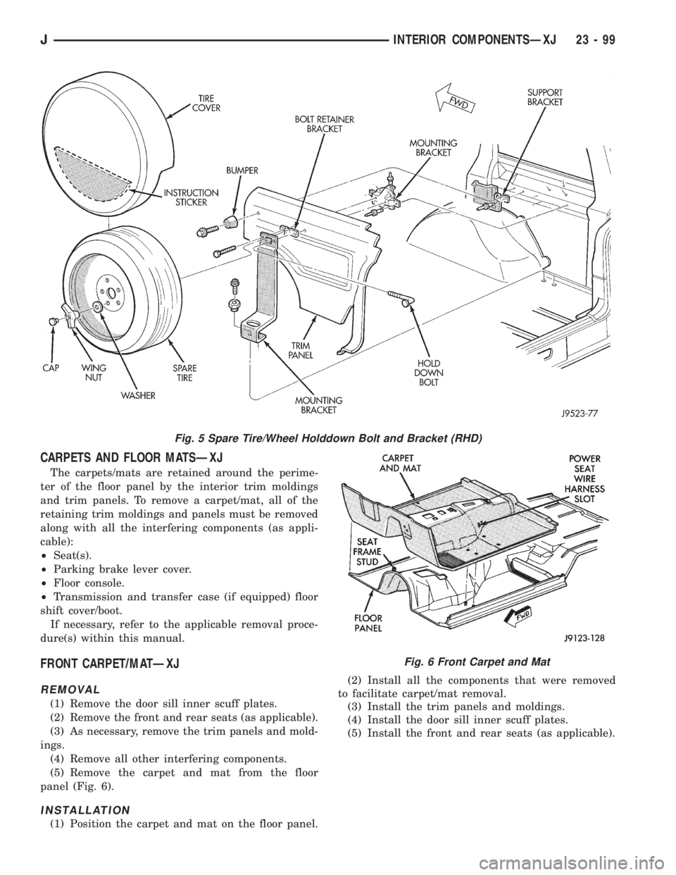
(5) Remove the carpet and mat from the floor
panel (Fig. 6).
INSTALLATION
(1) Position the carpet and mat on the floor panel.(2) Install all the components that were removed
to facilitate carpet/mat removal.
(3) Install the trim panels and moldings.
(4) Install the door sill inner scuff plates.
(5) Install the front and rear seats (as applicable).
Fig. 5 Spare Tire/Wheel Holddown Bolt and Bracket (RHD)
Fig. 6 Front Carpet and Mat
JINTERIOR COMPONENTSÐXJ 23 - 99
Page 1834 of 2198
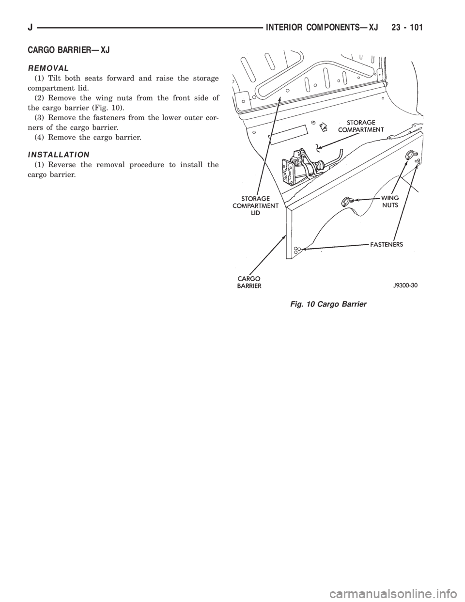
CARGO BARRIERÐXJ
REMOVAL
(1) Tilt both seats forward and raise the storage
compartment lid.
(2) Remove the wing nuts from the front side of
the cargo barrier (Fig. 10).
(3) Remove the fasteners from the lower outer cor-
ners of the cargo barrier.
(4) Remove the cargo barrier.
INSTALLATION
(1) Reverse the removal procedure to install the
cargo barrier.
Fig. 10 Cargo Barrier
JINTERIOR COMPONENTSÐXJ 23 - 101
Page 1884 of 2198
INTERIOR COMPONENTS
INDEX
page page
Add-A-TrunkÐYJ........................ 157
Bucket SeatsÐYJ........................ 153
CarpetÐYJ............................. 156
Floor ConsolesÐYJ...................... 155
Front Shoulder BeltsÐYJ.................. 154
Glove BoxÐYJ.......................... 152
Instrument Cluster and Gauge HousingsÐYJ.... 151Instrument Cluster BezelÐYJ............... 151
Instrument Panel ComponentsÐYJ........... 152
Instrument PanelÐYJ..................... 151
Rear Bench SeatÐYJ..................... 153
Rear Shoulder BeltsÐYJ................... 154
SeatsÐYJ............................. 153
SunvisorsÐYJ.......................... 155
INSTRUMENT PANELÐYJ
The instrument panel is constructed of sheet metal
and is attached to cowl panel with screws. The in-
strument panel and defroster grille pad is attached
to the instrument panel with screws.
INSTRUMENT CLUSTER AND GAUGE HOUSINGSÐ
YJ
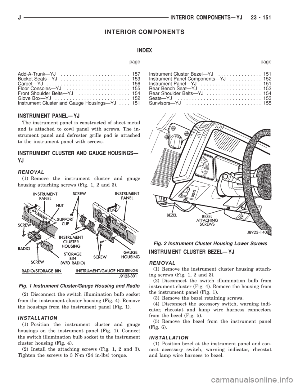
REMOVAL
(1) Remove the instrument cluster and gauge
housing attaching screws (Fig. 1, 2 and 3).
(2) Disconnect the switch illumination bulb socket
from the instrument cluster housing (Fig. 4). Remove
the housings from the instrument panel (Fig. 1).
INSTALLATION
(1) Position the instrument cluster and gauge
housings on the instrument panel (Fig. 1). Connect
the switch illumination bulb socket to the instrument
cluster housing (Fig. 4).
(2) Install the attaching screws (Fig. 1, 2 and 3).
Tighten the screws to 3 Nzm (24 in-lbs) torque.
INSTRUMENT CLUSTER BEZELÐYJ
REMOVAL
(1) Remove the instrument cluster housing attach-
ing screws (Fig. 1, 2 and 3).
(2) Disconnect the switch illumination bulb from
instrument cluster (Fig. 4). Remove the housing from
the instrument panel (Fig. 1).
(3) Remove the bezel retaining screws.
(4) Disconnect the accessory switch, warning indi-
cator, rheostat and lamp wire harness connectors
from the bezel (Fig. 5).
(5) Remove the bezel from the instrument panel
(Fig. 6).
INSTALLATION
(1) Position bezel at the instrument panel and con-
nect accessory switch, warning indicator, rheostat
and lamp wire harness to bezel.
Fig. 1 Instrument Cluster/Gauge Housing and Radio
Fig. 2 Instrument Cluster Housing Lower Screws
JINTERIOR COMPONENTSÐYJ 23 - 151
Page 1886 of 2198
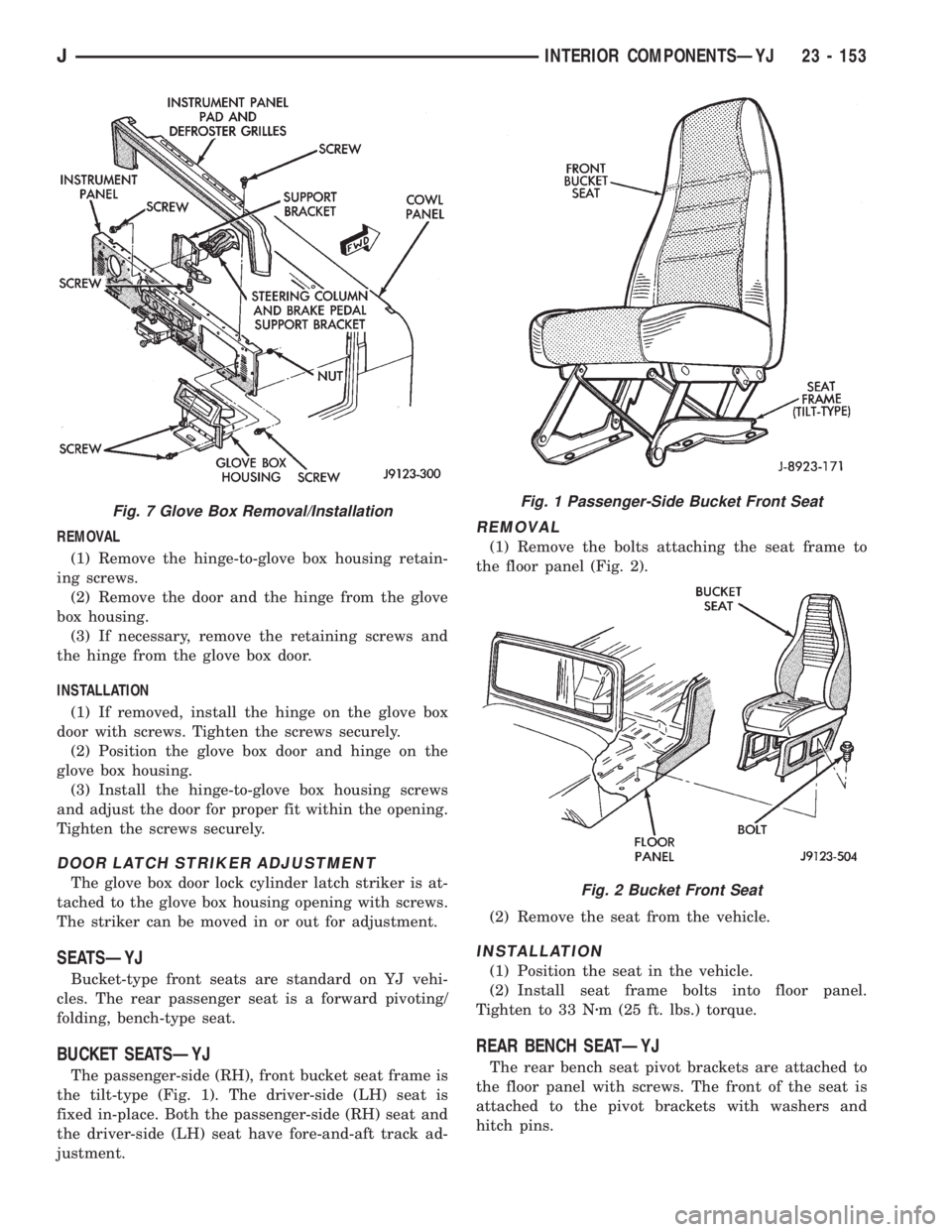
REMOVAL
(1) Remove the hinge-to-glove box housing retain-
ing screws.
(2) Remove the door and the hinge from the glove
box housing.
(3) If necessary, remove the retaining screws and
the hinge from the glove box door.
INSTALLATION
(1) If removed, install the hinge on the glove box
door with screws. Tighten the screws securely.
(2) Position the glove box door and hinge on the
glove box housing.
(3) Install the hinge-to-glove box housing screws
and adjust the door for proper fit within the opening.
Tighten the screws securely.
DOOR LATCH STRIKER ADJUSTMENT
The glove box door lock cylinder latch striker is at-
tached to the glove box housing opening with screws.
The striker can be moved in or out for adjustment.
SEATSÐYJ
Bucket-type front seats are standard on YJ vehi-
cles. The rear passenger seat is a forward pivoting/
folding, bench-type seat.
BUCKET SEATSÐYJ
The passenger-side (RH), front bucket seat frame is
the tilt-type (Fig. 1). The driver-side (LH) seat is
fixed in-place. Both the passenger-side (RH) seat and
the driver-side (LH) seat have fore-and-aft track ad-
justment.
REMOVAL
(1) Remove the bolts attaching the seat frame to
the floor panel (Fig. 2).
(2) Remove the seat from the vehicle.
INSTALLATION
(1) Position the seat in the vehicle.
(2) Install seat frame bolts into floor panel.
Tighten to 33 Nzm (25 ft. lbs.) torque.
REAR BENCH SEATÐYJ
The rear bench seat pivot brackets are attached to
the floor panel with screws. The front of the seat is
attached to the pivot brackets with washers and
hitch pins.
Fig. 7 Glove Box Removal/InstallationFig. 1 Passenger-Side Bucket Front Seat
Fig. 2 Bucket Front Seat
JINTERIOR COMPONENTSÐYJ 23 - 153
Page 1889 of 2198
CARPETÐYJ
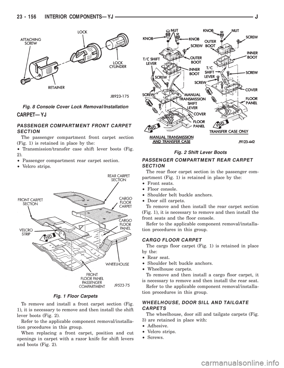
PASSENGER COMPARTMENT FRONT CARPET
SECTION
The passenger compartment front carpet section
(Fig. 1) is retained in place by the:
²Transmission/transfer case shift lever boots (Fig.
2).
²Passenger compartment rear carpet section.
²Velcro strips.
To remove and install a front carpet section (Fig.
1), it is necessary to remove and then install the shift
lever boots (Fig. 2).
Refer to the applicable component removal/installa-
tion procedures in this group.
When replacing a front carpet, position and cut
openings in carpet with a razor knife for shift levers
and boots (Fig. 2).
PASSENGER COMPARTMENT REAR CARPET
SECTION
The rear floor carpet section in the passenger com-
partment (Fig. 1) is retained in place by the:
²Front seats.
²Floor console.
²Shoulder belt buckle anchors.
²Door sill carpets.
To remove and then install the rear carpet section
(Fig. 1), it is necessary to remove and then install the
front seats and the floor console.
Refer to the applicable component removal/installa-
tion procedures in this group.
CARGO FLOOR CARPET
The cargo floor carpet (Fig. 1) is retained in place
by the:
²Rear seat.
²Shoulder belt buckle anchors.
²Wheelhouse carpets.
To remove and then install a cargo floor carpet, it
is necessary to remove and then install the rear seat.
Refer to the applicable component removal/installa-
tion procedures in this group.
WHEELHOUSE, DOOR SILL AND TAILGATE
CARPETS
The wheelhouse, door sill and tailgate carpets (Fig.
3) are retained in place with:
²Adhesive.
²Velcro strips.
²Screws.
Fig. 8 Console Cover Lock Removal/Installation
Fig. 1 Floor Carpets
Fig. 2 Shift Lever Boots
23 - 156 INTERIOR COMPONENTSÐYJJ