1995 JEEP CHEROKEE key battery
[x] Cancel search: key batteryPage 694 of 2198
POWER DOOR LOCKS
POWER DOOR LOCKS
Two relays provide power for the power door lock
motors. The Unlock relay provides power for the un-
lock circuits while the Lock relay powers the lock cir-
cuits. Either the power door lock switches or the
remote keyless entry module operate the Unlock and
Lock relays.
LOCK RELAY
Circuit M1 from fuse 9 in the fuse block powers cir-
cuit P38. When either power door lock switch is put
in the LOCK position, the switch connects circuit P38
to circuit P35. If the operator uses Remote Keyless
Entry (RKE), the RKE module powers circuit P35. In
either case, circuit P35 supplies power to the coil side
of the lock relay, causing the relay contacts to close.
Circuit Z1 provides ground for the coil side of the
lock relay.
When the lock relay contacts close, they connect
battery voltage from circuit P37 to circuit P2. Circuit
P2 then supplies battery voltage to the power door
lock motors to LOCK the doors.
When the power doors LOCK, ground for the mo-
tors is on circuit P34 through the normally closed
contacts in the door unlock relay to ground on circuit
Z1.
UNLOCK RELAY
Circuit M1 from fuse 9 in the fuse block powers cir-
cuit P38. When either power door lock switch is put
in the UNLOCK position, the switch connects circuit
P38 to circuit P36. If the operator uses Remote Key-
less Entry (RKE), the RKE module powers circuit
P36. In either case, circuit P36 supplies power to the
coil side of the unlock relay, causing the relay con-
tacts to close. Circuit Z1 provides ground for the coil
side of the unlock relay.
When the unlock relay contacts close, they connect
battery voltage from circuit P37 to circuit P34. Cir-
cuit P34 then supplies battery voltage to the power
door lock motors to UNLOCK the doors.
When the power doors UNLOCK, ground for the
motors is on circuit P2 through the normally closed
contacts in the door lock relay to ground on circuit
Z1.
REMOTE KEYLESS ENTRY MODULE
Circuit M1 from the ignition off draw (IOD) fuse in
cavity 9 of the fuse block supplies power to the Re-
mote Keyless Entry (RKE) module. Circuit F87 from
fuse 17 in the fuse block supplies power to the RKE
module when the ignition switch is in the START or
RUN position. Circuit Z1 provides ground for the
RKE module.
The RKE module UNLOCKS the doors by energiz-
ing the unlock relay on circuit P36. Refer to Unlock
Relay.
The module LOCKS the doors by energizing the
lock relay on circuit P35. Refer to Lock Relay.
HELPFUL INFORMATION
²Fuse 13 in the fuse block powers circuit P37. Cir-
cuit A7 from fuse 3 in the PDC feeds fuse 13 in the
fuse block.
²Circuit A7 from fuse 3 in the PDC also feeds fuse
16 in the PDC. PDC fuse 16 powers fuse 9 in the
fuse block. Fuse 9 protects the M1 circuit.
DIAGRAM INDEX
Component Page
Chime/Buzzer Module......................8W-61-5
Fuse 3 (PDC).........................8W-61-2, 6
Fuse 6 (PDC)...........................8W-61-5
Fuse 9 (Fuse Block).......................8W-61-2
Fuse 11 (Fuse Block)......................8W-61-2
Fuse 13 (Fuse Block)......................8W-61-2
Fuse 14 (Fuse Block)......................8W-61-2
Fuse 16 (PDC)........................8W-61-2, 6
Fuse 17 (Fuse Block)......................8W-61-5
Headlamp Delay Module....................8W-61-5
Ignition Switch..........................8W-61-5
Liftgate Lock Motor.......................8W-61-4
Power Door Lock Motors...................8W-61-4
Power Door Lock Relay....................8W-61-3
Power Door Lock Switches..................8W-61-2
Power Door Unlock Relay...................8W-61-3
Remote Keyless Entry (RKE) Module............8W-61-6
Telltale Connector........................8W-61-5
J8W-61 POWER DOOR LOCKSÐXJ VEHICLES 8W - 61 - 1
Page 854 of 2198
STARTING SYSTEM
STARTING SYSTEM
Circuit A0 from the battery is double crimped at
the positive battery post. One branch of circuit A0
(battery positive cable) connects to the engine starter
motor. The other A0 branch supplies voltage to the
bus bar in the power distribution center (PDC).
Fuse 7 in the PDC supplies battery voltage to the
contact side of the engine starter motor relay on cir-
cuit A4. When the coil side of the engine starter mo-
tor relay energizes, the contacts close and connect
circuit A4 to circuit T40. Circuit T40 supplies battery
voltage to the starter motor solenoid.
The ignition switch supplies battery voltage to the
coil side of the starter motor relay on circuit A41
when the key is moved to the START position.
Ground for the coil side of the starter motor relay is
supplied by the case grounded Park/Neutral position
switch. Circuit T41 connects the coil side of the relay
to the Park/Neutral position switch.
When the starter motor relay energizes and the
contacts close, circuit T40 supplies battery voltage to
the starter motor solenoid. Circuit A0 from the bat-
tery supplies voltage to the starter motor when the
solenoid energizes.HELPFUL INFORMATION
²The Park/Neutral switch closes when the trans-
mission is in either the PARK or NEUTRAL posi-
tions.
²Circuit T41 also connects to cavity 30 of the Pow-
ertrain Control Module (PCM). This input tells the
PCM the operator is starting the vehicle.
²Circuit A4 is double crimped at the contact side of
the starter motor relay. The A4 branch leaving the
relay powers fuse 13 in the PDC.
DIAGRAM INDEX
Component Page
Engine Starter Motor......................8W-21-2
Engine Starter Motor Relay..................8W-21-2
Ignition Switch..........................8W-21-2
PDC Fuse 6............................8W-21-2
PDC Fuse 7............................8W-21-2
PDC Fuse 13...........................8W-21-2
Powertrain Control Module..................8W-21-2
Park/Neutral Position Switch.................8W-21-2
Transmission Control Module.................8W-21-2
J8W-21 STARTING SYSTEMÐXJ-RHD 8W - 21 - 1
Page 1121 of 2198
at the engine cylinder head. Also tap the top of the
retainer to seat the valve locks.
(8) Install the engine cylinder head.
VALVE TIMING
Disconnect the spark plug wires and remove the
spark plugs.
Remove the engine cylinder head cover.
Remove the capscrews, bridge and pivot assembly,
and rocker arms from above the No.1 cylinder.
Alternately loosen each capscrew, one turn at a
time, to avoid damaging the bridge.
Rotate the crankshaft until the No.4 piston is at
top dead center (TDC) on the compression stroke.
Rotate the crankshaft counterclockwise (viewed
from the front of the engine) 90É.
Install a dial indicator on the end of the No.1 cyl-
inder intake valve push rod. Use rubber tubing to se-
cure the indicator stem on the push rod.
Set the dial indicator pointer at zero.
Rotate the crankshaft clockwise (viewed from the
front of the engine) until the dial indicator pointer
indicates 0.305 mm (0.012 inch) travel distance (lift).
The timing notch index on the vibration damper
should be aligned with the TDC mark on the timing
degree scale.
If the timing notch is more than 13 mm (1/2 inch)
away from the TDC mark in either direction, the
valve timing is incorrect.
If the valve timing is incorrect, the cause may be a
broken camshaft pin. It is not necessary to replace
the camshaft because of pin failure. A spring pin is
available for service replacement.
VIBRATION DAMPER
REMOVAL
(1) Disconnect negative cable from battery.
(2) Remove the serpentine drive belt and fan
shroud.
(3) Remove the vibration damper retaining bolt
and washer.
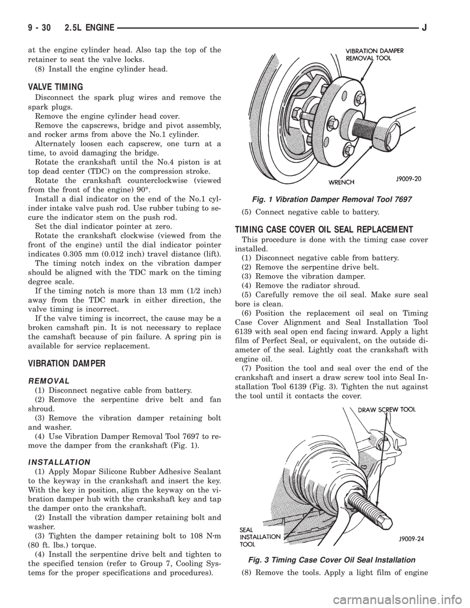
(4) Use Vibration Damper Removal Tool 7697 to re-
move the damper from the crankshaft (Fig. 1).
INSTALLATION
(1) Apply Mopar Silicone Rubber Adhesive Sealant
to the keyway in the crankshaft and insert the key.
With the key in position, align the keyway on the vi-
bration damper hub with the crankshaft key and tap
the damper onto the crankshaft.
(2) Install the vibration damper retaining bolt and
washer.
(3) Tighten the damper retaining bolt to 108 Nzm
(80 ft. lbs.) torque.
(4) Install the serpentine drive belt and tighten to
the specified tension (refer to Group 7, Cooling Sys-
tems for the proper specifications and procedures).(5) Connect negative cable to battery.
TIMING CASE COVER OIL SEAL REPLACEMENT
This procedure is done with the timing case cover
installed.
(1) Disconnect negative cable from battery.
(2) Remove the serpentine drive belt.
(3) Remove the vibration damper.
(4) Remove the radiator shroud.
(5) Carefully remove the oil seal. Make sure seal
bore is clean.
(6) Position the replacement oil seal on Timing
Case Cover Alignment and Seal Installation Tool
6139 with seal open end facing inward. Apply a light
film of Perfect Seal, or equivalent, on the outside di-
ameter of the seal. Lightly coat the crankshaft with
engine oil.
(7) Position the tool and seal over the end of the
crankshaft and insert a draw screw tool into Seal In-
stallation Tool 6139 (Fig. 3). Tighten the nut against
the tool until it contacts the cover.
(8) Remove the tools. Apply a light film of engine
Fig. 1 Vibration Damper Removal Tool 7697
Fig. 3 Timing Case Cover Oil Seal Installation
9 - 30 2.5L ENGINEJ
Page 1122 of 2198
oil on the vibration damper hub contact surface of
the seal.
(9) Apply Mopar Silicone Rubber Adhesive Sealant
to the keyway in the crankshaft and insert the key.
With the key inserted in the keyway in the crank-
shaft, install the vibration damper, washer and bolt.
Lubricate and tighten the bolt to 108 Nzm (80 ft. lbs.)
torque.
(10) Install the serpentine belt and tighten to the
specified tension (refer to Group 7, Cooling Systems
for the proper specifications and procedures).
(11) Install the radiator shroud.
(12) Connect negative cable to battery.
TIMING CASE COVER
REMOVAL
(1) Disconnect negative cable from battery.
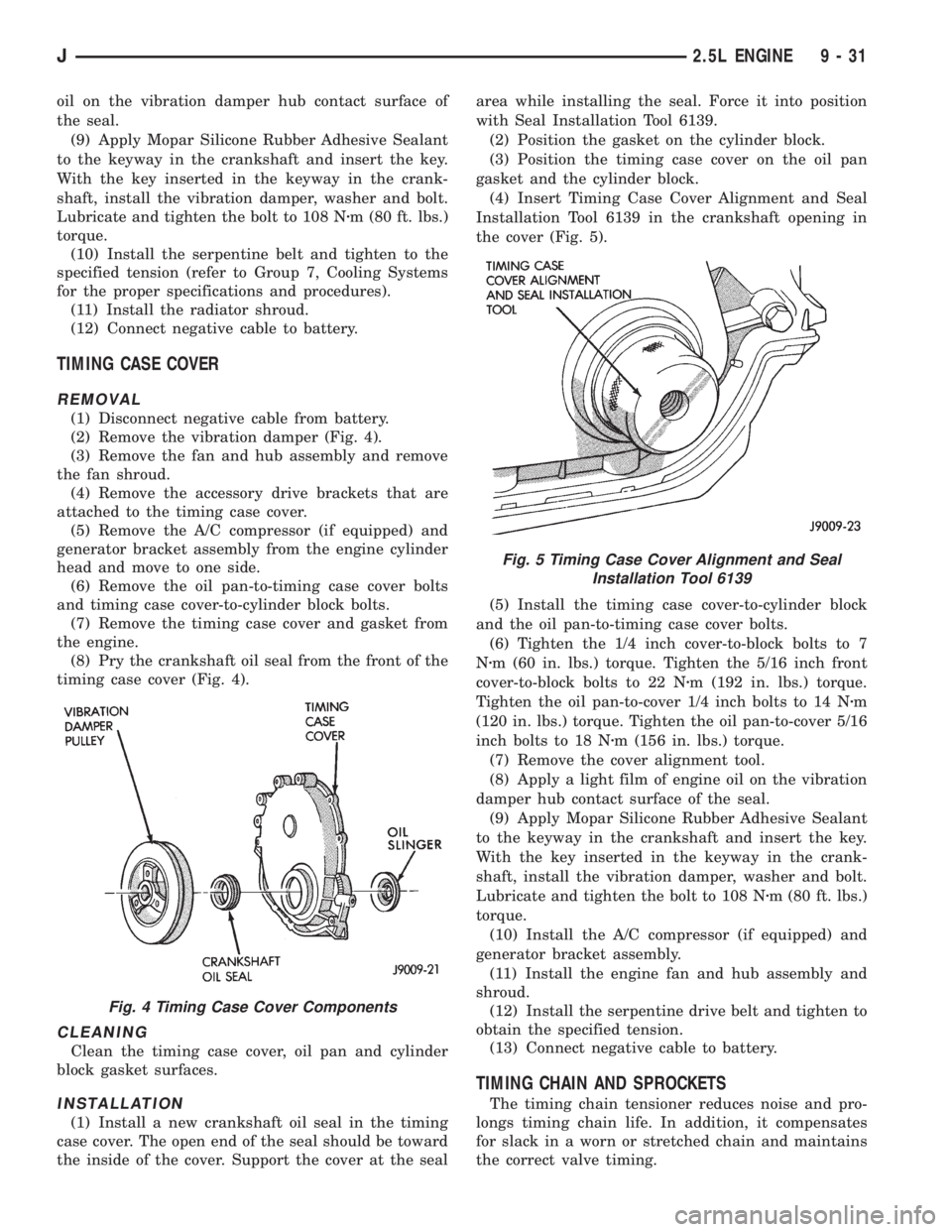
(2) Remove the vibration damper (Fig. 4).
(3) Remove the fan and hub assembly and remove
the fan shroud.
(4) Remove the accessory drive brackets that are
attached to the timing case cover.
(5) Remove the A/C compressor (if equipped) and
generator bracket assembly from the engine cylinder
head and move to one side.
(6) Remove the oil pan-to-timing case cover bolts
and timing case cover-to-cylinder block bolts.
(7) Remove the timing case cover and gasket from
the engine.
(8) Pry the crankshaft oil seal from the front of the
timing case cover (Fig. 4).
CLEANING
Clean the timing case cover, oil pan and cylinder
block gasket surfaces.
INSTALLATION
(1) Install a new crankshaft oil seal in the timing
case cover. The open end of the seal should be toward
the inside of the cover. Support the cover at the sealarea while installing the seal. Force it into position
with Seal Installation Tool 6139.
(2) Position the gasket on the cylinder block.
(3) Position the timing case cover on the oil pan
gasket and the cylinder block.
(4) Insert Timing Case Cover Alignment and Seal
Installation Tool 6139 in the crankshaft opening in
the cover (Fig. 5).
(5) Install the timing case cover-to-cylinder block
and the oil pan-to-timing case cover bolts.
(6) Tighten the 1/4 inch cover-to-block bolts to 7
Nzm (60 in. lbs.) torque. Tighten the 5/16 inch front
cover-to-block bolts to 22 Nzm (192 in. lbs.) torque.
Tighten the oil pan-to-cover 1/4 inch bolts to 14 Nzm
(120 in. lbs.) torque. Tighten the oil pan-to-cover 5/16
inch bolts to 18 Nzm (156 in. lbs.) torque.
(7) Remove the cover alignment tool.
(8) Apply a light film of engine oil on the vibration
damper hub contact surface of the seal.
(9) Apply Mopar Silicone Rubber Adhesive Sealant
to the keyway in the crankshaft and insert the key.
With the key inserted in the keyway in the crank-
shaft, install the vibration damper, washer and bolt.
Lubricate and tighten the bolt to 108 Nzm (80 ft. lbs.)
torque.
(10) Install the A/C compressor (if equipped) and
generator bracket assembly.
(11) Install the engine fan and hub assembly and
shroud.
(12) Install the serpentine drive belt and tighten to
obtain the specified tension.
(13) Connect negative cable to battery.
TIMING CHAIN AND SPROCKETS
The timing chain tensioner reduces noise and pro-
longs timing chain life. In addition, it compensates
for slack in a worn or stretched chain and maintains
the correct valve timing.
Fig. 4 Timing Case Cover Components
Fig. 5 Timing Case Cover Alignment and Seal
Installation Tool 6139
J2.5L ENGINE 9 - 31
Page 1123 of 2198
REMOVAL
(1) Disconnect negative cable from battery.
(2) Remove the fan and shroud.
(3) Remove the serpentine drive belt.
(4) Remove the crankshaft vibration damper.
(5) Remove the timing case cover.
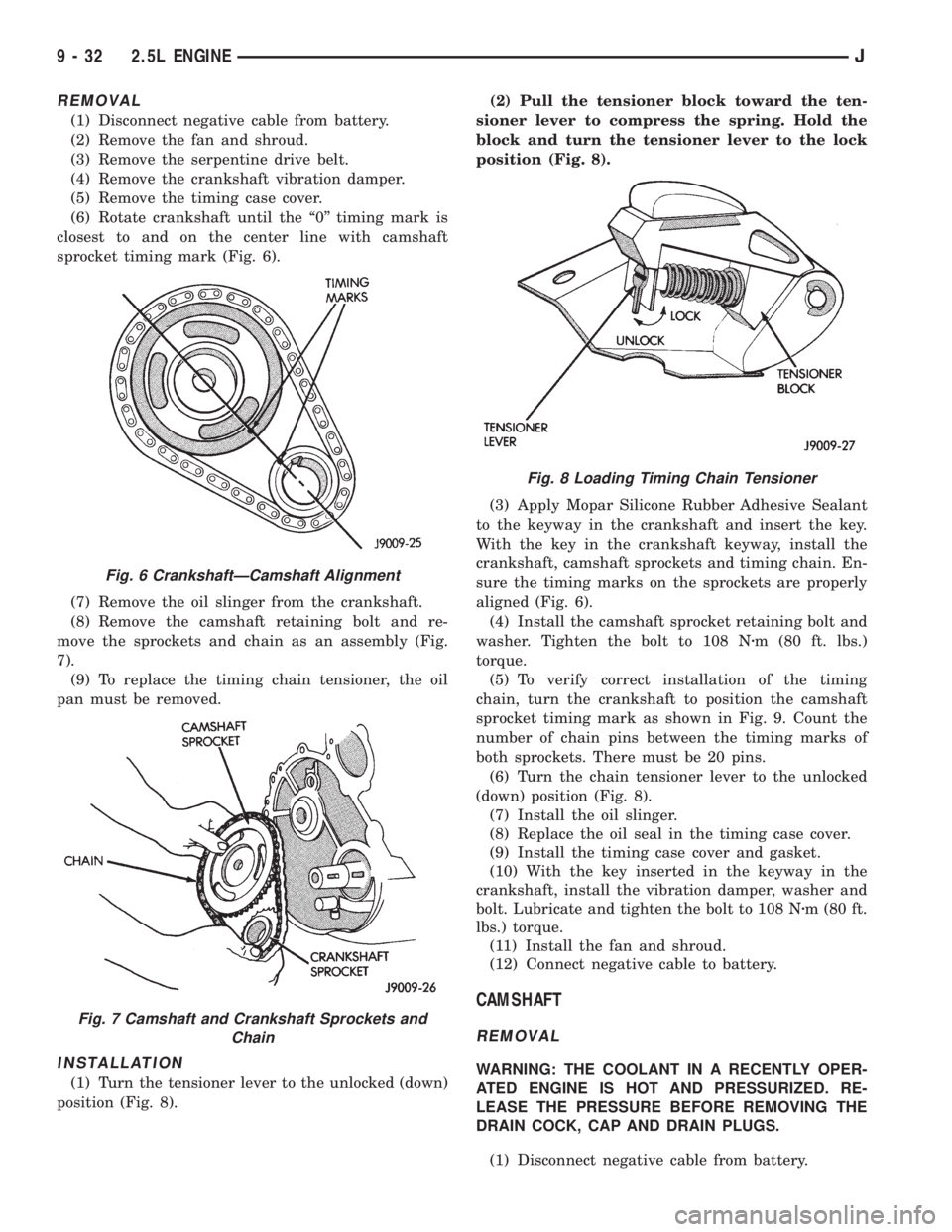
(6) Rotate crankshaft until the ``0'' timing mark is
closest to and on the center line with camshaft
sprocket timing mark (Fig. 6).
(7) Remove the oil slinger from the crankshaft.
(8) Remove the camshaft retaining bolt and re-
move the sprockets and chain as an assembly (Fig.
7).
(9) To replace the timing chain tensioner, the oil
pan must be removed.
INSTALLATION
(1) Turn the tensioner lever to the unlocked (down)
position (Fig. 8).(2) Pull the tensioner block toward the ten-
sioner lever to compress the spring. Hold the
block and turn the tensioner lever to the lock
position (Fig. 8).
(3) Apply Mopar Silicone Rubber Adhesive Sealant
to the keyway in the crankshaft and insert the key.
With the key in the crankshaft keyway, install the
crankshaft, camshaft sprockets and timing chain. En-
sure the timing marks on the sprockets are properly
aligned (Fig. 6).
(4) Install the camshaft sprocket retaining bolt and
washer. Tighten the bolt to 108 Nzm (80 ft. lbs.)
torque.
(5) To verify correct installation of the timing
chain, turn the crankshaft to position the camshaft
sprocket timing mark as shown in Fig. 9. Count the
number of chain pins between the timing marks of
both sprockets. There must be 20 pins.
(6) Turn the chain tensioner lever to the unlocked
(down) position (Fig. 8).
(7) Install the oil slinger.
(8) Replace the oil seal in the timing case cover.
(9) Install the timing case cover and gasket.
(10) With the key inserted in the keyway in the
crankshaft, install the vibration damper, washer and
bolt. Lubricate and tighten the bolt to 108 Nzm (80 ft.
lbs.) torque.
(11) Install the fan and shroud.
(12) Connect negative cable to battery.
CAMSHAFT
REMOVAL
WARNING: THE COOLANT IN A RECENTLY OPER-
ATED ENGINE IS HOT AND PRESSURIZED. RE-
LEASE THE PRESSURE BEFORE REMOVING THE
DRAIN COCK, CAP AND DRAIN PLUGS.
(1) Disconnect negative cable from battery.
Fig. 6 CrankshaftÐCamshaft Alignment
Fig. 7 Camshaft and Crankshaft Sprockets and
Chain
Fig. 8 Loading Timing Chain Tensioner
9 - 32 2.5L ENGINEJ
Page 1163 of 2198
VIBRATION DAMPER
REMOVAL
(1) Disconnect negative cable from battery.
(2) Remove the serpentine drive belt and fan
shroud.
(3) Remove the vibration damper retaining bolt
and washer.
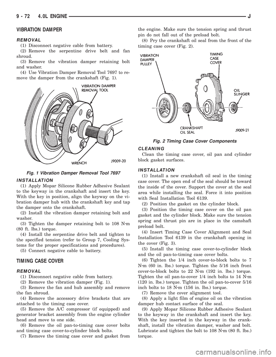
(4) Use Vibration Damper Removal Tool 7697 to re-
move the damper from the crankshaft (Fig. 1).
INSTALLATION
(1) Apply Mopar Silicone Rubber Adhesive Sealant
to the keyway in the crankshaft and insert the key.
With the key in position, align the keyway on the vi-
bration damper hub with the crankshaft key and tap
the damper onto the crankshaft.
(2) Install the vibration damper retaining bolt and
washer.
(3) Tighten the damper retaining bolt to 108 Nzm
(80 ft. lbs.) torque.
(4) Install the serpentine drive belt and tighten to
the specified tension (refer to Group 7, Cooling Sys-
tems for the proper specifications and procedures).
(5) Connect negative cable to battery.
TIMING CASE COVER
REMOVAL
(1) Disconnect negative cable from battery.
(2) Remove the vibration damper (Fig. 1).
(3) Remove the fan and hub assembly and remove
the fan shroud.
(4) Remove the accessory drive brackets that are
attached to the timing case cover.
(5) Remove the A/C compressor (if equipped) and
generator bracket assembly from the engine cylinder
head and move to one side.
(6) Remove the oil pan-to-timing case cover bolts
and timing case cover-to-cylinder block bolts.
(7) Remove the timing case cover and gasket fromthe engine. Make sure the tension spring and thrust
pin do not fall out of the preload bolt.
(8) Pry the crankshaft oil seal from the front of the
timing case cover (Fig. 2).
CLEANING
Clean the timing case cover, oil pan and cylinder
block gasket surfaces.
INSTALLATION
(1) Install a new crankshaft oil seal in the timing
case cover. The open end of the seal should be toward
the inside of the cover. Support the cover at the seal
area while installing the seal. Force it into position
with Seal Installation Tool 6139.
(2) Position the gasket on the cylinder block.
(3) Position the timing case cover on the oil pan
gasket and the cylinder block. Make sure the tension
spring and thrust pin are in place in the camshaft
preload bolt.
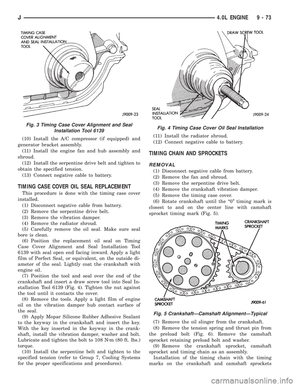
(4) Insert Timing Case Cover Alignment and Seal
Installation Tool 6139 in the crankshaft opening in
the cover (Fig. 3).
(5) Install the timing case cover-to-cylinder block
and the oil pan-to-timing case cover bolts.
(6) Tighten the 1/4 inch cover-to-block bolts to 7
Nzm (60 in. lbs.) torque. Tighten the 5/16 inch front
cover-to-block bolts to 22 Nzm (192 in. lbs.) torque.
Tighten the oil pan-to-cover 1/4 inch bolts to 14 Nzm
(120 in. lbs.) torque. Tighten the oil pan-to-cover 5/16
inch bolts to 18 Nzm (156 in. lbs.) torque.
(7) Remove the cover alignment tool.
(8) Apply a light film of engine oil on the vibration
damper hub contact surface of the seal.
(9) Apply Mopar Silicone Rubber Adhesive Sealant
to the keyway in the crankshaft and insert the key.
With the key inserted in the keyway in the crank-
shaft, install the vibration damper, washer and bolt.
Lubricate and tighten the bolt to 108 Nzm (80 ft. lbs.)
torque.Fig. 1 Vibration Damper Removal Tool 7697
Fig. 2 Timing Case Cover Components
9 - 72 4.0L ENGINEJ
Page 1164 of 2198
(10) Install the A/C compressor (if equipped) and
generator bracket assembly.
(11) Install the engine fan and hub assembly and
shroud.
(12) Install the serpentine drive belt and tighten to
obtain the specified tension.
(13) Connect negative cable to battery.
TIMING CASE COVER OIL SEAL REPLACEMENT
This procedure is done with the timing case cover
installed.
(1) Disconnect negative cable from battery.
(2) Remove the serpentine drive belt.
(3) Remove the vibration damper.
(4) Remove the radiator shroud.
(5) Carefully remove the oil seal. Make sure seal
bore is clean.
(6) Position the replacement oil seal on Timing
Case Cover Alignment and Seal Installation Tool
6139 with seal open end facing inward. Apply a light
film of Perfect Seal, or equivalent, on the outside di-
ameter of the seal. Lightly coat the crankshaft with
engine oil.
(7) Position the tool and seal over the end of the
crankshaft and insert a draw screw tool into Seal In-
stallation Tool 6139 (Fig. 4). Tighten the nut against
the tool until it contacts the cover.
(8) Remove the tools. Apply a light film of engine
oil on the vibration damper hub contact surface of
the seal.
(9) Apply Mopar Silicone Rubber Adhesive Sealant
to the keyway in the crankshaft and insert the key.
With the key inserted in the keyway in the crank-
shaft, install the vibration damper, washer and bolt.
Lubricate and tighten the bolt to 108 Nzm (80 ft. lbs.)
torque.
(10) Install the serpentine belt and tighten to the
specified tension (refer to Group 7, Cooling Systems
for the proper specifications and procedures).(11) Install the radiator shroud.
(12) Connect negative cable to battery.
TIMING CHAIN AND SPROCKETS
REMOVAL
(1) Disconnect negative cable from battery.
(2) Remove the fan and shroud.
(3) Remove the serpentine drive belt.
(4) Remove the crankshaft vibration damper.
(5) Remove the timing case cover.
(6) Rotate crankshaft until the ``0'' timing mark is
closest to and on the center line with camshaft
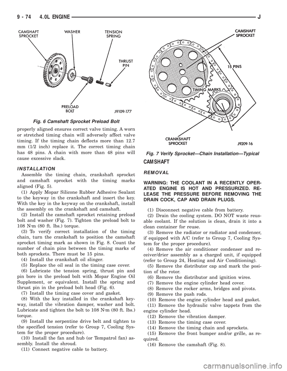
sprocket timing mark (Fig. 5).
(7) Remove the oil slinger from the crankshaft.
(8) Remove the tension spring and thrust pin from
the preload bolt (Fig. 6). Remove the camshaft
sprocket retaining preload bolt and washer.
(9) Remove the crankshaft sprocket, camshaft
sprocket and timing chain as an assembly.
Installation of the timing chain with the timing
marks on the crankshaft and camshaft sprockets
Fig. 3 Timing Case Cover Alignment and Seal
Installation Tool 6139Fig. 4 Timing Case Cover Oil Seal Installation
Fig. 5 CrankshaftÐCamshaft AlignmentÐTypical
J4.0L ENGINE 9 - 73
Page 1165 of 2198
properly aligned ensures correct valve timing. A worn
or stretched timing chain will adversely affect valve
timing. If the timing chain deflects more than 12.7
mm (1/2 inch) replace it. The correct timing chain
has 48 pins. A chain with more than 48 pins will
cause excessive slack.
INSTALLATION
Assemble the timing chain, crankshaft sprocket
and camshaft sprocket with the timing marks
aligned (Fig. 5).
(1) Apply Mopar Silicone Rubber Adhesive Sealant
to the keyway in the crankshaft and insert the key.
With the key in the keyway on the crankshaft, install
the assembly on the crankshaft and camshaft.
(2) Install the camshaft sprocket retaining preload
bolt and washer (Fig. 7). Tighten the preload bolt to
108 Nzm (80 ft. lbs.) torque.
(3) To verify correct installation of the timing
chain, turn the crankshaft to position the camshaft
sprocket timing mark as shown in Fig. 8. Count the
number of chain pins between the timing marks of
both sprockets. There must be 15 pins.
(4) Install the crankshaft oil slinger.
(5) Replace the oil seal in the timing case cover.
(6) Lubricate the tension spring, thrust pin and
pin bore in the preload bolt with Mopar Engine Oil
Supplement, or equivalent. Install the spring and
thrust pin in the preload bolt head (Fig. 6).
(7) Install the timing case cover and gasket.
(8) With the key installed in the crankshaft key-
way, install the vibration damper, washer and bolt.
Lubricate and tighten the bolt to 108 Nzm (80 ft. lbs.)
torque.
(9) Install the serpentine drive belt and tighten to
the specified tension (refer to Group 7, Cooling Sys-
tem for the proper procedure).
(10) Install the fan and hub (or Tempatrol fan) as-
sembly. Install the shroud.
(11) Connect negative cable to battery.
CAMSHAFT
REMOVAL
WARNING: THE COOLANT IN A RECENTLY OPER-
ATED ENGINE IS HOT AND PRESSURIZED. RE-
LEASE THE PRESSURE BEFORE REMOVING THE
DRAIN COCK, CAP AND DRAIN PLUGS.
(1) Disconnect negative cable from battery.
(2) Drain the cooling system. DO NOT waste reus-
able coolant. If the solution is clean, drain it into a
clean container for reuse.
(3) Remove the radiator or radiator and condenser,
if equipped with A/C (refer to Group 7, Cooling Sys-
tem for the proper procedure).
(4) Remove the air conditioner condenser and re-
ceiver/drier assembly as a charged unit, if equipped
(refer to Group 24, Heating and Air Conditioning).
(5) Remove the distributor cap and mark the posi-
tion of the rotor.
(6) Remove the distributor and ignition wires.
(7) Remove the engine cylinder head cover.
(8) Remove the rocker arms, bridges and pivots.
(9) Remove the push rods.
(10) Remove the engine cylinder head and gasket.
(11) Remove the hydraulic valve tappets from the
engine cylinder head.
(12) Remove the vibration damper.
(13) Remove the timing case cover.
(14) Remove the timing chain and sprockets.
(15) Remove the front bumper and/or grille, as re-
quired.
(16) Remove the camshaft (Fig. 8).
Fig. 6 Camshaft Sprocket Preload Bolt
Fig. 7 Verify SprocketÐChain InstallationÐTypical
9 - 74 4.0L ENGINEJ