1995 JEEP CHEROKEE change time
[x] Cancel search: change timePage 230 of 2198

EXAMPLES:
²If the lamp (Figs. 5 or 6) flashes 1 time, pauses
and flashes 2 more times, a flashing Diagnostic Trou-
ble Code (DTC) number 12 is indicated. If this code is
observed, it is indicating that the battery has been
disconnected within the last 50 key-on cycles. It
could also indicate that battery voltage has been dis-
connected to the PCM. In either case, other DTC's
may have been erased.
²If the lamp flashes 1 time, pauses and flashes 7
more times, a flashing Diagnostic Trouble Code
(DTC) number 17 is indicated.
²If the lamp flashes 3 times, pauses and flashes 5
more times, a flashing Diagnostic Trouble Code
(DTC) number 35 is indicated.
After any stored DTC information has been ob-
served, the display will end with a flashing DTC
number 55. This will indicate the end of all stored in-
formation.
ERASING TROUBLE CODES
After the problem has been repaired, the DRB scan
tool must be used to erase a DTC. Refer to the ap-
propriate Powertrain Diagnostic Procedures service
manual for operation of the DRB scan tool.
DRB SCAN TOOL
For operation of the DRB scan tool, refer to the ap-
propriate Powertrain Diagnostic Procedures service
manual.
PRELIMINARY CHECKS
ENGINE COOLING SYSTEM OVERHEATING
Establish what driving conditions caused the com-
plaint. Abnormal loads on the cooling system such as
the following may be the cause.
1. PROLONGED IDLE, VERY HIGH AMBIENT
TEMPERATURE, SLIGHT TAIL WIND AT IDLE,
SLOW TRAFFIC, TRAFFIC JAMS, HIGH
SPEED, OR STEEP GRADES:
Driving techniques that avoid overheating are:
²Idle with A/C off when temperature gauge is at
end of normal range.
²Increasing engine speed for more air flow is recom-
mended.
2. TRAILER TOWING:
Consult Trailer Towing section of owners manual.
Do not exceed limits.
3. AIR CONDITIONING; ADD-ON OR AFTER
MARKET:
A maximum cooling package should have been or-
dered with vehicle if add-on or after market A/C is
installed. If not, maximum cooling system compo-
nents should be installed for model involved per
manufacturer's specifications.
4. RECENT SERVICE OR ACCIDENT REPAIR:
Determine if any recent service has been performed
on vehicle that may effect cooling system. This may
be:
²Engine adjustments (incorrect timing)
²Slipping engine accessory drive belt(s)
²Brakes (possibly dragging)
²Changed parts (incorrect water pump rotating in
wrong direction)
²Reconditioned radiator or cooling system refilling
(possibly under-filled or air trapped in system).
If investigation reveals none of the previous
items as a cause for an engine overheating com-
plaint, refer to following Cooling System Diag-
nosis charts.
These charts are to be used as a quick-reference
only. Refer to the group text for information.
Fig. 7 Data Link ConnectorÐXJ ModelsÐTypical
Fig. 8 Data Link ConnectorÐYJ ModelsÐTypical
JCOOLING SYSTEM DIAGNOSIS 7 - 5
Page 243 of 2198
temperature, coolant is allowed to flow to the radia-
tor. This provides quick engine warmup and overall
temperature control.
An arrow plus the wordUPis stamped on the
front flange next to the air bleed. The wordsTO
RADare stamped on one arm of the thermostat.
They indicate the proper installed position.
The same thermostat is used for winter and sum-
mer seasons. An engine should not be operated with-
out a thermostat, except for servicing or testing.
Operating without a thermostat causes other prob-
lems. These are: longer engine warmup time, unreli-
able warmup performance, increased exhaust
emissions and crankcase condensation. This conden-
sation can result in sludge formation.
CAUTION: Do not operate an engine without a ther-
mostat, except for servicing or testing.
ON-BOARD DIAGNOSTICS
XJ and YJ models are equipped with On-Board Di-
agnostics for certain cooling system components. Re-
fer to On-Board Diagnostics (OBD) in the Diagnosis
section of this group for additional information. If the
powertrain control module (PCM) detects low engine
coolant temperature, it will record a Diagnostic Trou-
ble Code (DTC) in the PCM memory. The DTC num-
ber for low coolant temperature is 17. Do not change
a thermostat for lack of heat as indicated by the in-
strument panel gauge or heater performance unless a
DTC number 17 is present. Refer to the Diagnosis
section of this group for other probable causes. For
other DTC numbers, refer to On-Board Diagnostics
in the General Diagnosis section of Group 14, Fuel
Systems.
The DTC can also be accessed through the DRB
scan tool. Refer to the appropriate Powertrain Diag-
nostic Procedures manual for diagnostic information
and operation of the DRB scan tool.
REMOVAL
WARNING: DO NOT LOOSEN THE RADIATOR
DRAINCOCK WITH THE SYSTEM HOT AND PRES-
SURIZED. SERIOUS BURNS FROM THE COOLANT
CAN OCCUR.
DO NOT WASTE reusable coolant. If the solution
is clean, drain the coolant into a clean container for
reuse.
(1) Drain the coolant from the radiator until the
level is below the thermostat housing.
WARNING: CONSTANT TENSION HOSE CLAMPS
ARE USED ON MOST COOLING SYSTEM HOSES.
WHEN REMOVING OR INSTALLING, USE ONLY
TOOLS DESIGNED FOR SERVICING THIS TYPE OF
CLAMP, SUCH AS SPECIAL CLAMP TOOL (NUMBER
6094) (FIG. 15). SNAP-ON CLAMP TOOL (NUMBER
HPC-20) MAY BE USED FOR LARGER CLAMPS. AL-
WAYS WEAR SAFETY GLASSES WHEN SERVICING
CONSTANT TENSION CLAMPS.
CAUTION: A number or letter is stamped into the
tongue of constant tension clamps (Fig. 16). If re-
placement is necessary, use only an original equip-
ment clamp with matching number or letter.
(2) Remove radiator upper hose and heater hose at
thermostat housing.
(3) Disconnect wiring connector at engine coolant
temperature sensor.
(4) Remove thermostat housing mounting bolts,
thermostat housing, gasket and thermostat (Fig. 17).
Discard old gasket.
(5) Clean the gasket mating surfaces.
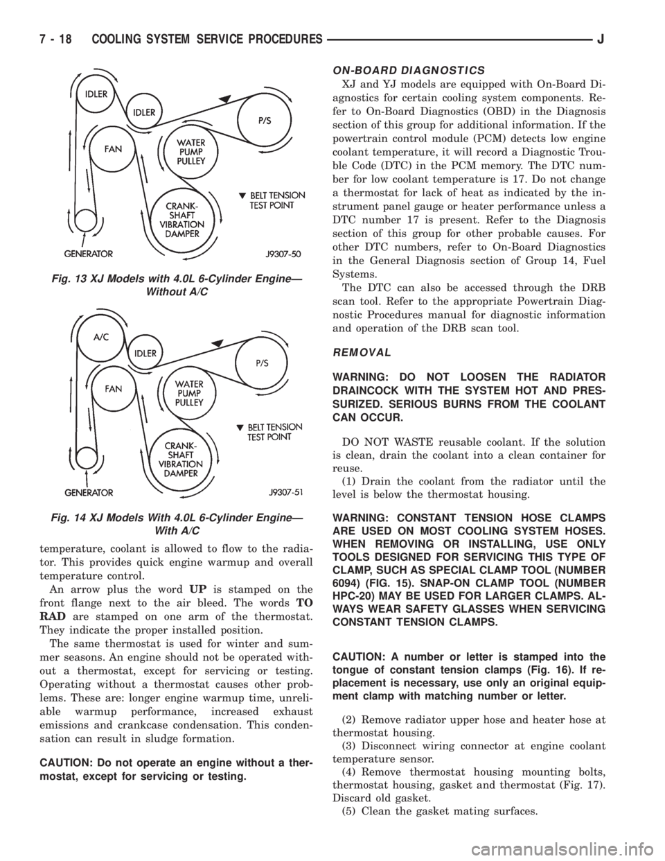
Fig. 13 XJ Models with 4.0L 6-Cylinder EngineÐ
Without A/C
Fig. 14 XJ Models With 4.0L 6-Cylinder EngineÐ
With A/C
7 - 18 COOLING SYSTEM SERVICE PROCEDURESJ
Page 273 of 2198
BATTERY
GENERAL INFORMATION
The storage battery is a device used to store elec-
trical energy potential in a chemical form. When an
electrical load is applied to the battery terminals, an
electrochemical reaction occurs within the battery.
This reaction causes the battery to discharge electri-
cal current.
The battery is made up of 6 individual cells that
are connected in series. Each cell contains positively
charged plate groups made of lead oxide, and nega-
tively charged plate groups made of sponge lead.
These dissimilar metal plates are submerged in a
sulfuric acid and water solution called electrolyte.
As the battery discharges, a gradual chemical
change takes place within each cell. The sulfuric acid
in the electrolyte combines with the plate materials,
causing both plates to change to lead sulfate. At the
same time, oxygen from the positive plate material
combines with hydrogen from the sulfuric acid, caus-
ing the electrolyte to become mainly water.
The chemical changes within the battery are
caused by movement of excess or free electrons be-
tween the positive and negative plate groups. Thismovement of electrons produces a flow of electrical
current through the load device attached to the bat-
tery terminals.
As the plate materials become more similar chem-
ically, and the electrolyte becomes less acid, the volt-
age potential of each cell is reduced. However, by
charging the battery with a voltage higher than that
of the battery, the process is reversed.
Charging the battery gradually changes the sul-
fated lead plates back into sponge lead and lead ox-
ide, and the water back into sulfuric acid. This action
restores the difference in electron charges deposited
on the plates, and the voltage potential of the battery
cells.
For a battery to remain useful, it must be able to
produce high-amperage current over an extended pe-
riod. A battery must also be able to accept a charge,
so that its voltage potential may be restored.
In addition to producing and storing electrical en-
ergy, the battery serves as a capacitor or voltage sta-
bilizer for the vehicle electrical system. It absorbs
abnormal or transient voltages caused by switching
of any of the vehicle's electrical components.
The battery is vented to release excess gas that is
created when the battery is being charged or dis-
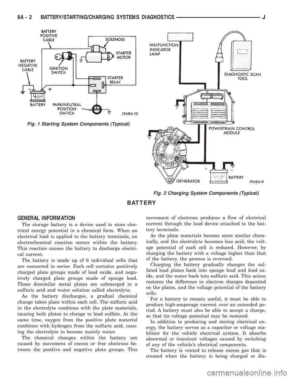
Fig. 1 Starting System Components (Typical)
Fig. 2 Charging System Components (Typical)
8A - 2 BATTERY/STARTING/CHARGING SYSTEMS DIAGNOSTICSJ
Page 304 of 2198
OVERHEAD CONSOLE
CONTENTS
page page
DIAGNOSIS............................. 2
GENERAL INFORMATION.................. 1SERVICE PROCEDURES................... 5
GENERAL INFORMATION
An overhead console featuring an electronic com-
pass and thermometer is an available option for XJ
(Cherokee) models. Following are general descrip-
tions of major components used in the overhead con-
sole. Refer to Group 8W - Wiring Diagrams for
complete circuit descriptions and diagrams.
COMPASS
The compass will display the direction in which the
vehicle is pointed using the eight major compass
headings (Examples: north is N, northeast is NE). It
does not display the headings in actual degrees. The
display is turned on or off using the COMP/TEMP
button to the left of the display.
The self-calibrating compass unit requires no ad-
justing in normal use. The only calibration that may
prove necessary is to drive the vehicle in 3 complete
circles, on level ground, in not less than 48 seconds.
This will reorient the unit to its vehicle.
The unit also will compensate for magnetism the
body of the vehicle may acquire during normal use.
However, avoid placing anything magnetic directly on
the roof of the vehicle. Magnetic mounts for an an-
tenna, a repair order hat or a funeral procession flag
can exceed the compensating ability of the compass
unit if placed on the roof panel. Magnetic bit drivers
used on the fasteners that hold the assembly to the
roof header can also affect compass operation.
If the vehicle roof should become magnetized, the
demagnetizing and calibration procedures may be re-
quired to restore proper operation.
THERMOMETER
The thermometer displays the outside ambient
temperature. The temperature displayed can be
changed from Fahrenheit to Celsius using the US/
METRIC button. The displayed temperature is not
an instant reading of conditions, but an average tem-
perature. It may take the unit several minutes to re-
act to a major temperature change such as driving
out of a heated garage into winter temperatures.
When the ignition switch is turned OFF, the lastdisplayed temperature reading stays in memory.
When the ignition switch is turned ON again, the
thermometer will display the memory temperature
for one minute; then update the display to the cur-
rent average temperature reading within five min-
utes.
READING AND COURTESY LAMPS
All reading and courtesy lamps in the overhead
console are activated by the door jamb switches.
When all doors and the liftgate are closed, the lamps
can be individually activated by depressing the corre-
sponding lens. When a door and/or the liftgate is
open, depressing the lamp lens switches will not turn
the lamps off. Refer to Group 8L - Lamps, for diag-
nosis and service of these lamps.
KEYLESS ENTRY RECEIVER
The overhead console houses the keyless entry re-
ceiver. Refer to Group 8P - Power Locks, for diagno-
sis and service of this component.
REMOTE GARAGE DOOR OPENER STORAGE
A compartment in the overhead console is designed
to hold most remote garage door opener transmitters.
The transmitter is mounted within the compartment
with an adhesive-backed hook and loop fastener
patch. Then one to three pegs are selected and
mounted on a post on the inside of the storage com-
partment door. The pegs may be stacked, if neces-
sary. The peg(s) selected must be long enough to
activate the button of the transmitter each time the
storage compartment door is depressed.
SUNGLASSES STORAGE
A flocked storage compartment for sunglasses is in-
cluded in the overhead console. This compartment
features a push/push-type latch and a viscous damp-
ening system for a fluid opening motion.
JOVERHEAD CONSOLE 8C - 1
Page 308 of 2198

SERVICE PROCEDURES
COMPASS VARIATION ADJUSTMENT
Variance is the difference between magnetic north
and geographic north. In some areas, the difference
between magnetic and geographic north is great
enough to cause the compass to give false readings. If
this occurs, the variance must be set.
To set the variance:
(1) Using the map in Fig. 3, find your geographic
location and note the zone number.
(2) Turn ignition switch to the ON position.
(3) Depress both the US/METRIC and COMP/
TEMP buttons. Hold down until VAR is displayed.
This takes about 5 seconds.
(4) Release both buttons.
(5) Press the US/METRIC button to step through
the numbers until the zone number for your area ap-
pears in the display.
(6) Press the COMP/TEMP button to enter this
zone number into compass unit memory.
(7) Confirm correct directions are indicated.
COMPASS CALIBRATION
CAUTION: DO NOT place any external magnets
such as magnetic roof mount antennas, in the vicin-ity of the compass. DO NOT use magnetic tools
when servicing the overhead console.
The compass features a self-calibrating design,
which simplifies the calibration procedure. This fea-
ture automatically updates the compass calibration
while the vehicle is being driven. This takes into ac-
count small changes in residual magnetism the vehi-
cle may acquire during normal use. Do not attempt
to calibrate the compass near large metal objects
such as other vehicles, large buildings or bridges.
Whenever the compass is calibrated manually,
the variation number must also be reset. See
Variation Adjustment Procedure, in this group.
Calibrate the compass manually as follows:
(1) Start the engine.
(2) Depress both the US/METRIC and COMP/
TEMP buttons. Hold down until CAL is displayed.
This takes about 10 seconds and appears about 5 sec-
onds after VAR is displayed.
(3) Release both buttons.
(4) Drive vehicle on a level surface that is away
from large metal objects through 3 or more complete
circles in not less than 48 seconds. The CAL message
will disappear to indicate that the compass is now
calibrated.
If CAL message remains in display, either
there is excessive magnetism near the compass
or the unit is faulty. Repeat the demagnetizing
and calibration procedures at least one more
time.
If the wrong direction is still indicated, the
area selected may be too close to a strong mag-
netic field. Repeat the calibration procedure in
another location.
COMPASS DEMAGNETIZING
The tool used to degauss or demagnetize the for-
ward console attaching screw and roof panel is the
Miller Tool 6029. Equivalent units must be rated as
continuous duty for 110/115 volts and 60Hz. They
must also have a field strength of over 350 gauss at
1/4-inch beyond the tip of the probe.
The degaussing tool is used to demagnetize both
the roof panel and the console forward mounting
screw, as follows:
(1) Be sure the ignition switch is in the OFF posi-
tion before you begin the demagnetizing procedure.
(2) Plug in the degaussing tool, while keeping the
tool at least 2 feet away from the compass unit.
(3) Slowly approach the head of the forward
mounting screw with the plastic coated tip of the de-
gaussing tool. Contact the head of the screw for
about 2 seconds.Fig. 3 Variance Settings
JOVERHEAD CONSOLE 8C - 5
Page 485 of 2198
nal B (driver side) with the positive lead. The volt-
meter should read 10-14 volts.
Steps 3, 4 or 5 above will confirm system operation.
Indicator light illumination means that there is
power available at the output of the switch, but does
not confirm that power is reaching the rear window
grid lines.
If the rear window defogger does not operate, the
problem should be isolated in the following manner:
(1) Confirm that ignition switch is in ON position.
(2) Ensure that the heated rear window feed and
ground wires are connected to the glass. Confirm
that the ground wire has continuity to ground.
(3) Check fuses 8 and 18 (XJ), or fuses 6 and 9
(YJ) in fuseblock module. Fuses must be tight in
their receptacles and all electrical connections must
be secure.
When the above steps have been completed and the
system is still inoperative, one or more of the follow-
ing is faulty:
²defogger switch²relay/timer
²rear window grid lines (all grid lines would have
to be broken or one of the feed wires disconnected for
the entire system to be inoperative).
If turning the switch ON produces severe voltmeter
deflection, check for a short circuit.
REAR WINDOW GLASS GRID
To detect breaks in grid lines, the following proce-
dure is required:
(1) Turn ignition switch to the ON position. Turn
rear defogger switch ON. The indicator lamp should
light.
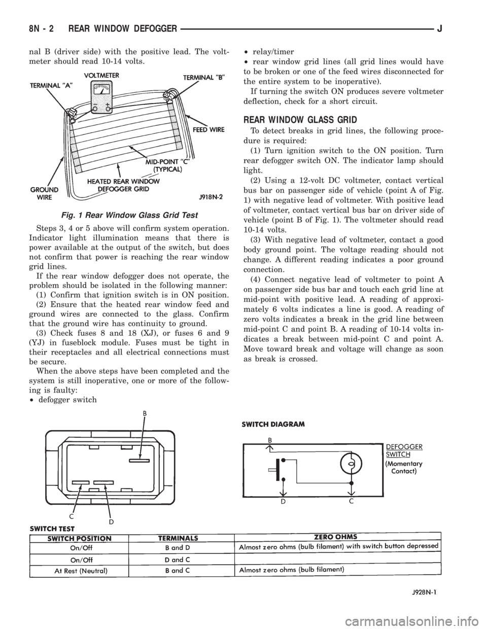
(2) Using a 12-volt DC voltmeter, contact vertical
bus bar on passenger side of vehicle (point A of Fig.
1) with negative lead of voltmeter. With positive lead
of voltmeter, contact vertical bus bar on driver side of
vehicle (point B of Fig. 1). The voltmeter should read
10-14 volts.
(3) With negative lead of voltmeter, contact a good
body ground point. The voltage reading should not
change. A different reading indicates a poor ground
connection.
(4) Connect negative lead of voltmeter to point A
on passenger side bus bar and touch each grid line at
mid-point with positive lead. A reading of approxi-
mately 6 volts indicates a line is good. A reading of
zero volts indicates a break in the grid line between
mid-point C and point B. A reading of 10-14 volts in-
dicates a break between mid-point C and point A.
Move toward break and voltage will change as soon
as break is crossed.
Fig. 1 Rear Window Glass Grid Test
8N - 2 REAR WINDOW DEFOGGERJ
Page 578 of 2198
Circuit G7 from the vehicle speed sensor provides
an input signal to the PCM. The G7 circuit connects
to cavity 47 of the PCM.
The PCM provides a ground for the vehicle speed
sensor signal (circuit G7) through circuit K4. Circuit
K4 connects to cavity 4 of the PCM.
HELPFUL INFORMATION
²Circuit G7 splices to the speedometer, and daytime
running lights module (DRL).
²Circuit K7 splices to supply 8 volts to the camshaft
position sensor and crankshaft position sensor.
Circuit K4 splices to supply ground for the signals
from the following:
²Heated oxygen sensor
²Camshaft position sensor
²Crankshaft position sensor
²Throttle position sensor
²Manifold absolute pressure sensor
²Engine coolant temperature sensor
²Intake air temperature sensor
HEATED OXYGEN SENSOR
When the fuel pump relay contacts close, they con-
nect circuits A14 and A141. Circuit A141 splices to
supply voltage to the heated oxygen sensor.
Circuit K41 delivers the signal from the heated ox-
ygen sensor to the PCM. Circuit K41 connects to cav-
ity 41 of the PCM.
The PCM provides a ground for the heated oxygen
sensor signal (circuit K41) through circuit K4. Circuit
K4 connects to cavity 4 of the PCM connector.
Circuit Z12 provides a ground for the heater circuit
in the sensor.
Circuit Z12 terminates at the right side of the en-
gine.
HELPFUL INFORMATION
²Circuit A141 also supplies battery voltage to the
fuel pump.
Circuit K4 splices to supply ground for the signals
from the following:
²Heated oxygen sensor
²Camshaft position sensor
²Crankshaft position sensor
²Intake air temperature sensor
²Throttle position sensor
²Manifold absolute pressure sensor
²Engine coolant temperature sensor
²Vehicle speed sensor
CAMSHAFT POSITION SENSOR
The Powertrain Control Module (PCM) supplies 8
volts to the camshaft position sensor (in distributor)
on circuit K7. Circuit K7 connects to cavity 7 of the
PCM.The PCM receives the camshaft position sensor sig-
nal on circuit K44. Circuit K44 connects to cavity 44
of the PCM.
The PCM provides a ground for the camshaft posi-
tion sensor signal (circuit K44) through circuit K4.
Circuit K4 connects to cavity 4 of the PCM.
HELPFUL INFORMATION
²Circuit K7 splices to supply 8 volts to the crank-
shaft position sensor and the vehicle speed sensor.
Circuit K4 splices to supply ground for the signals
from the following:
²Heated oxygen sensor
²Camshaft position sensor
²Crankshaft position sensor
²Intake air temperature sensor
²Throttle position sensor
²Manifold absolute pressure sensor
²Engine coolant temperature sensor
²Vehicle speed sensor
CRANKSHAFT POSITION SENSOR
The Powertrain Control Module (PCM) supplies 8
volts to the crankshaft position sensor on circuit K7.
Circuit K7 connects to cavity 7 of the PCM.
The PCM receives the crankshaft position sensor
signal on circuit K24. Circuit K24 connects to cavity
24 of the PCM.
The PCM provides a ground for the crankshaft po-
sition sensor (circuit K24) through circuit K4. Circuit
K4 connects to cavity 4 of the PCM.
HELPFUL INFORMATION
²Circuit K7 splices to supply 8 volts to the camshaft
position sensor and the vehicle speed sensor.
Circuit K4 splices to supply ground for the signals
from the following:
²Heated oxygen sensor
²Camshaft position sensor
²Crankshaft position sensor
²Intake air temperature sensor
²Throttle position sensor
²Manifold absolute pressure sensor
²Engine coolant temperature sensor
²Vehicle speed sensor
ENGINE COOLANT TEMPERATURE SENSOR
The engine coolant temperature sensor provides an
input to the Powertrain Control Module (PCM) on
circuit K2. From circuit K2, the engine coolant tem-
perature sensor draws up to 5 volts from the PCM.
The sensor is a variable resistor. As coolant temper-
ature changes, the resistance in the sensor changes,
causing a change in current draw. The K2 circuit
connects to cavity 2 of the PCM.
J8W-30 FUEL/IGNITIONÐXJ VEHICLES 8W - 30 - 3
Page 612 of 2198
INSTRUMENT CLUSTER
INDEX
page page
ABS Warning Lamp........................ 2
Brake Warning Lamp....................... 2
Charging System Indicator Lamp............... 3
Cluster Ground............................ 3
Diagram Index............................. 3
Engine Coolant Temperature Gauge............ 1
Engine Coolant Temperature Warning Lamp...... 1
Fuel Gauge.............................. 1
High-Beam Indicator Lamp................... 2
Instrument Cluster......................... 1Low Fuel Warning Lamp..................... 1
Low Washer Fluid Warning Lamp.............. 2
Malfunction Indicator Lamp (MIL)............... 2
Manual Transmission Up-Shift Lamp............ 2
Oil Pressure Gauge........................ 2
Oil Pressure Warning Lamp.................. 2
Seat Belt Indicator Warning Lamp.............. 2
Speedometer............................. 2
Tachometer.............................. 2
Turn Signal Indicator Lamps.................. 2
INSTRUMENT CLUSTER
The instrument cluster contains the gauges and
warning lamps. All gauges have magnetic move-
ments.
When the ignition switch is in the START or RUN
position, circuit A21 feeds circuit F87 through fuse 17
in the fuse block. Circuit A1 from fuse 6 in the Power
Distribution Center (PDC) supplies voltage to circuit
A21. Circuit A1 is HOT at all times.
Circuit F87 connects to the cluster connector to
power the gauges and to the telltale connector to
power the warning lamps.
Circuit E2 from fuse 19 in the fuse block feeds the
illumination lamps. Circuit E2 originates at the head-
lamp switch and continues through fuse 19. The
headlamp switch powers circuit E2 when the parking
lamps or headlamp are ON.
Circuit Z2 provides ground for the indicator lamps
and illumination lamps.
ENGINE COOLANT TEMPERATURE GAUGE
Circuit G20 connects the engine coolant tempera-
ture gauge to the engine coolant temperature sensor.
The sensor is a variable resistor and case grounded to
the engine. Circuit F87 connects to the instrument
cluster left connector and supplies voltage for the
gauge.
The gauge uses two coils. Current passing through
the coils creates a magnetic field. Position of the
gauge needle is controlled by the amount of current
passing through the coils to ground at the sensor.
ENGINE COOLANT TEMPERATURE WARNING
LAMP
Circuit G20 connects the engine coolant tempera-
ture warning lamp to the engine coolant temperature
switch. When the switch closes, battery voltage from
circuit F87 flows through the lamp to ground through
the switch on circuit G20. The engine coolant tem-
perature switch is case grounded to the engine. Cir-cuit F87 connects to the instrument cluster connector
and supplies voltage for the lamp.
Circuit G20 also connects to the warning lamp to
ground when the ignition switch is in the START
position. When the ignition switch is in the START
position, the lamp illuminates for a bulb test.
FUEL GAUGE
The fuel level sensor is a variable resistor. Circuit
G4 connects the fuel level sensor to the fuel gauge in
the instrument cluster. Circuit F87 from fuse 17 in
the fuse block supplies voltage to the fuel gauge. The
fuel level sensor draws voltage from circuit F87
through the fuel gauge on circuit G4. Circuit G4
connects to circuit 57 in the fuel pump module har-
ness. Circuit 57 connects to the fuel level sensor.
Circuit 99 in the fuel pump module harness con-
nects to circuit Z1. Circuit Z1 provides the ground
path for the fuel level sensor. The grounding point for
circuit Z1 is the left side of the cowl panel.
As current flows through the coils in the fuel gauge,
it creates a magnetic field. One of the coils in the
gauge receives fixed current. The other coil is con-
nected to the level sensor. The magnetic field controls
the position of the fuel gauge pointer.
The fuel level sensor contains a variable resistor. As
the position of the float arm on the fuel level sensor
changes, the resistor changes the current flow
through second coil in the fuel gauge. A change in
current flow alters the magnetic field in the fuel
gauge, which changes the pointer position.
LOW FUEL WARNING LAMP
Circuit G4 connects the fuel level sensor to the fuel
gauge. The low fuel level module at the rear of the
gauge monitors resistance in circuit G4. The low fuel
level module powers an light emitting diode (LED)
when the resistance in circuit G4 reaches a calibrated
level. The LED illuminates the Low Fuel indicator.
Refer to Group 8E for additional information.
J8W-40 INSTRUMENT CLUSTERÐXJ VEHICLES 8W - 40 - 1