1995 JEEP CHEROKEE light
[x] Cancel search: lightPage 1238 of 2198
The engine will not operate if the PCM does not re-
ceive a crankshaft position sensor input.
ENGINE COOLANT TEMPERATURE SENSORÐPCM
INPUT
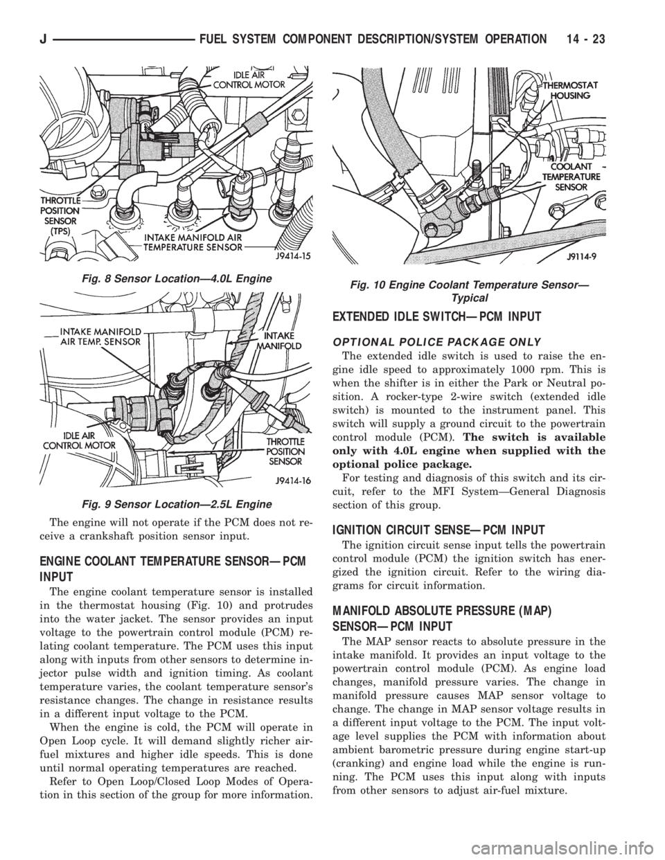
The engine coolant temperature sensor is installed
in the thermostat housing (Fig. 10) and protrudes
into the water jacket. The sensor provides an input
voltage to the powertrain control module (PCM) re-
lating coolant temperature. The PCM uses this input
along with inputs from other sensors to determine in-
jector pulse width and ignition timing. As coolant
temperature varies, the coolant temperature sensor's
resistance changes. The change in resistance results
in a different input voltage to the PCM.
When the engine is cold, the PCM will operate in
Open Loop cycle. It will demand slightly richer air-
fuel mixtures and higher idle speeds. This is done
until normal operating temperatures are reached.
Refer to Open Loop/Closed Loop Modes of Opera-
tion in this section of the group for more information.
EXTENDED IDLE SWITCHÐPCM INPUT
OPTIONAL POLICE PACKAGE ONLY
The extended idle switch is used to raise the en-
gine idle speed to approximately 1000 rpm. This is
when the shifter is in either the Park or Neutral po-
sition. A rocker-type 2-wire switch (extended idle
switch) is mounted to the instrument panel. This
switch will supply a ground circuit to the powertrain
control module (PCM).The switch is available
only with 4.0L engine when supplied with the
optional police package.
For testing and diagnosis of this switch and its cir-
cuit, refer to the MFI SystemÐGeneral Diagnosis
section of this group.
IGNITION CIRCUIT SENSEÐPCM INPUT
The ignition circuit sense input tells the powertrain
control module (PCM) the ignition switch has ener-
gized the ignition circuit. Refer to the wiring dia-
grams for circuit information.
MANIFOLD ABSOLUTE PRESSURE (MAP)
SENSORÐPCM INPUT
The MAP sensor reacts to absolute pressure in the
intake manifold. It provides an input voltage to the
powertrain control module (PCM). As engine load
changes, manifold pressure varies. The change in
manifold pressure causes MAP sensor voltage to
change. The change in MAP sensor voltage results in
a different input voltage to the PCM. The input volt-
age level supplies the PCM with information about
ambient barometric pressure during engine start-up
(cranking) and engine load while the engine is run-
ning. The PCM uses this input along with inputs
from other sensors to adjust air-fuel mixture.
Fig. 8 Sensor LocationÐ4.0L Engine
Fig. 9 Sensor LocationÐ2.5L Engine
Fig. 10 Engine Coolant Temperature SensorÐ
Typical
JFUEL SYSTEM COMPONENT DESCRIPTION/SYSTEM OPERATION 14 - 23
Page 1264 of 2198
IDLE AIR CONTROL MOTOR TEST
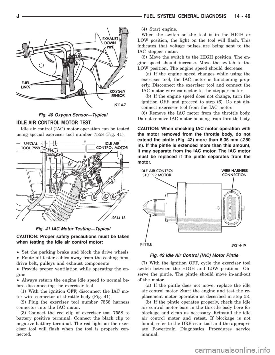
Idle air control (IAC) motor operation can be tested
using special exerciser tool number 7558 (Fig. 41).
CAUTION: Proper safety precautions must be taken
when testing the idle air control motor:
²Set the parking brake and block the drive wheels
²Route all tester cables away from the cooling fans,
drive belt, pulleys and exhaust components
²Provide proper ventilation while operating the en-
gine
²Always return the engine idle speed to normal be-
fore disconnecting the exerciser tool
(1) With the ignition OFF, disconnect the IAC mo-
tor wire connector at throttle body (Fig. 41).
(2) Plug the exerciser tool number 7558 harness
connector into the IAC motor.
(3) Connect the red clip of exerciser tool 7558 to
battery positive terminal. Connect the black clip to
negative battery terminal. The red light on the exer-
ciser tool will flash when the tool is properly con-
nected.(4) Start engine.
When the switch on the tool is in the HIGH or
LOW position, the light on the tool will flash. This
indicates that voltage pulses are being sent to the
IAC stepper motor.
(5) Move the switch to the HIGH position. The en-
gine speed should increase. Move the switch to the
LOW position. The engine speed should decrease.
(a) If the engine speed changes while using the
exerciser tool, the IAC motor is functioning prop-
erly. Disconnect the exerciser tool and connect the
IAC motor wire connector to the stepper motor.
(b) If the engine speed does not change, turn the
ignition OFF and proceed to step (6). Do not dis-
connect exerciser tool from the IAC motor.
(6) Remove the IAC motor from the throttle body.
Do not remove IAC motor housing from throttle body.
CAUTION: When checking IAC motor operation with
the motor removed from the throttle body, do not
extend the pintle (Fig. 42) more than 6.35 mm (.250
in). If the pintle is extended more than this amount,
it may separate from the IAC motor. The IAC motor
must be replaced if the pintle separates from the
motor.
(7) With the ignition OFF, cycle the exerciser tool
switch between the HIGH and LOW positions. Ob-
serve the pintle. The pintle should move in-and-out
of the motor.
(a) If the pintle does not move, replace the idle
air control motor. Start the engine and test the re-
placement motor operation as described in step (5).
(b) If the pintle operates properly, check the idle
air control motor bore in the throttle body bore for
blockage and clean as necessary. Reinstall the idle
air control motor and retest. If blockage is not
found, refer to the DRB scan tool and the appropri-
ate Powertrain Diagnostics Procedures service
manual.
Fig. 40 Oxygen SensorÐTypical
Fig. 41 IAC Motor TestingÐTypical
Fig. 42 Idle Air Control (IAC) Motor Pintle
JFUEL SYSTEM GENERAL DIAGNOSIS 14 - 49
Page 1280 of 2198
INSTALLATION
(1) Install throttle body and new gasket. Tighten
throttle body mounting bolts to 12 Nzm (9 ft. lbs.)
torque.
(2) Connect idle air control motor and throttle po-
sition sensor wire connectors.
(3) Connect throttle linkage to throttle arm.
CAUTION: When the automatic transmission throttle
cable is connected, it MUST be adjusted.
(4) If equipped with an automatic transmission,
connect and adjust the transmission line pressure ca-
ble. Refer to Group 21, Transmissions for adjustment
procedure.
(5) Install air cleaner hose to throttle body.
(6) Connect negative battery cable to battery.
THROTTLE POSITION SENSOR (TPS)
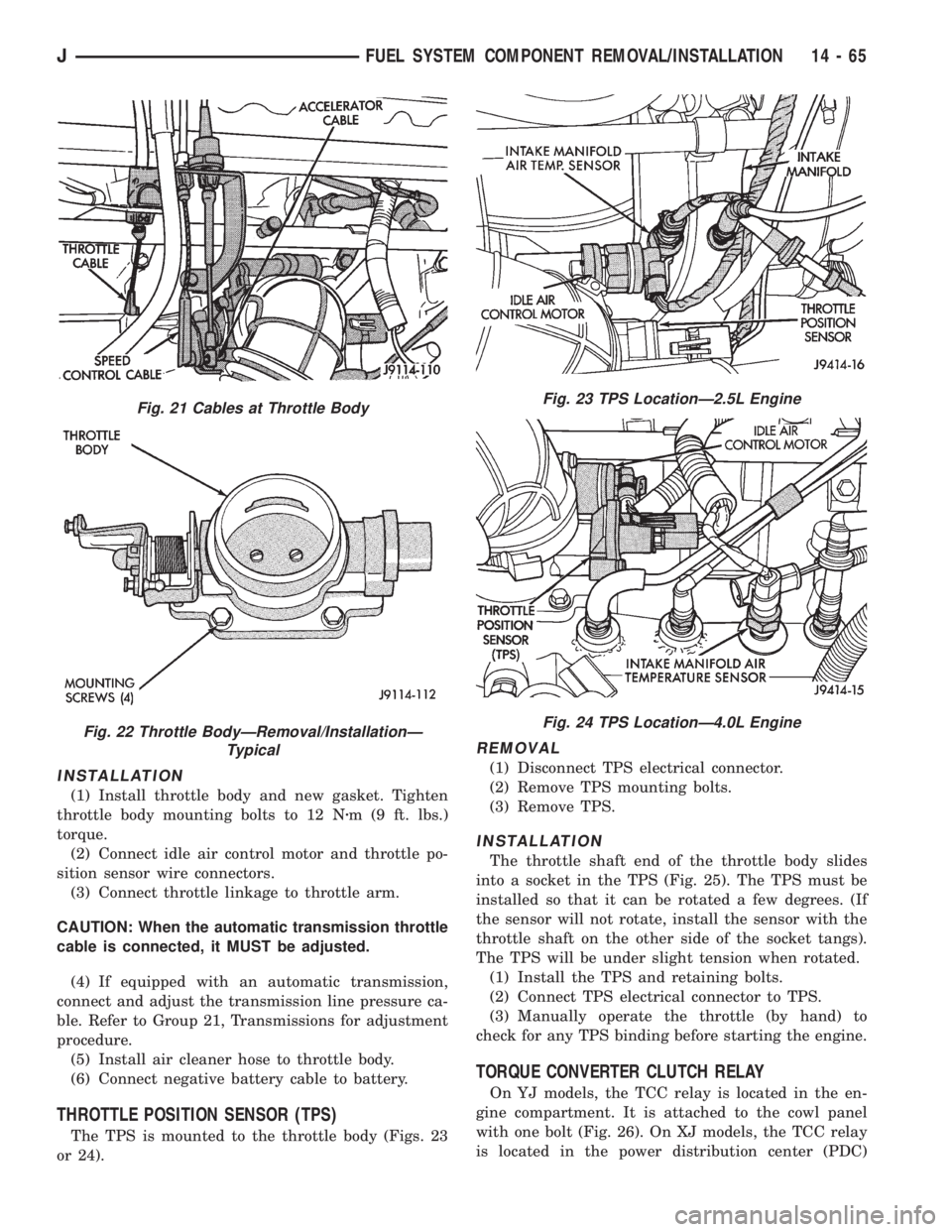
The TPS is mounted to the throttle body (Figs. 23
or 24).
REMOVAL
(1) Disconnect TPS electrical connector.
(2) Remove TPS mounting bolts.
(3) Remove TPS.
INSTALLATION
The throttle shaft end of the throttle body slides
into a socket in the TPS (Fig. 25). The TPS must be
installed so that it can be rotated a few degrees. (If
the sensor will not rotate, install the sensor with the
throttle shaft on the other side of the socket tangs).
The TPS will be under slight tension when rotated.
(1) Install the TPS and retaining bolts.
(2) Connect TPS electrical connector to TPS.
(3) Manually operate the throttle (by hand) to
check for any TPS binding before starting the engine.
TORQUE CONVERTER CLUTCH RELAY
On YJ models, the TCC relay is located in the en-
gine compartment. It is attached to the cowl panel
with one bolt (Fig. 26). On XJ models, the TCC relay
is located in the power distribution center (PDC)
Fig. 21 Cables at Throttle Body
Fig. 22 Throttle BodyÐRemoval/InstallationÐ
Typical
Fig. 23 TPS LocationÐ2.5L Engine
Fig. 24 TPS LocationÐ4.0L Engine
JFUEL SYSTEM COMPONENT REMOVAL/INSTALLATION 14 - 65
Page 1314 of 2198
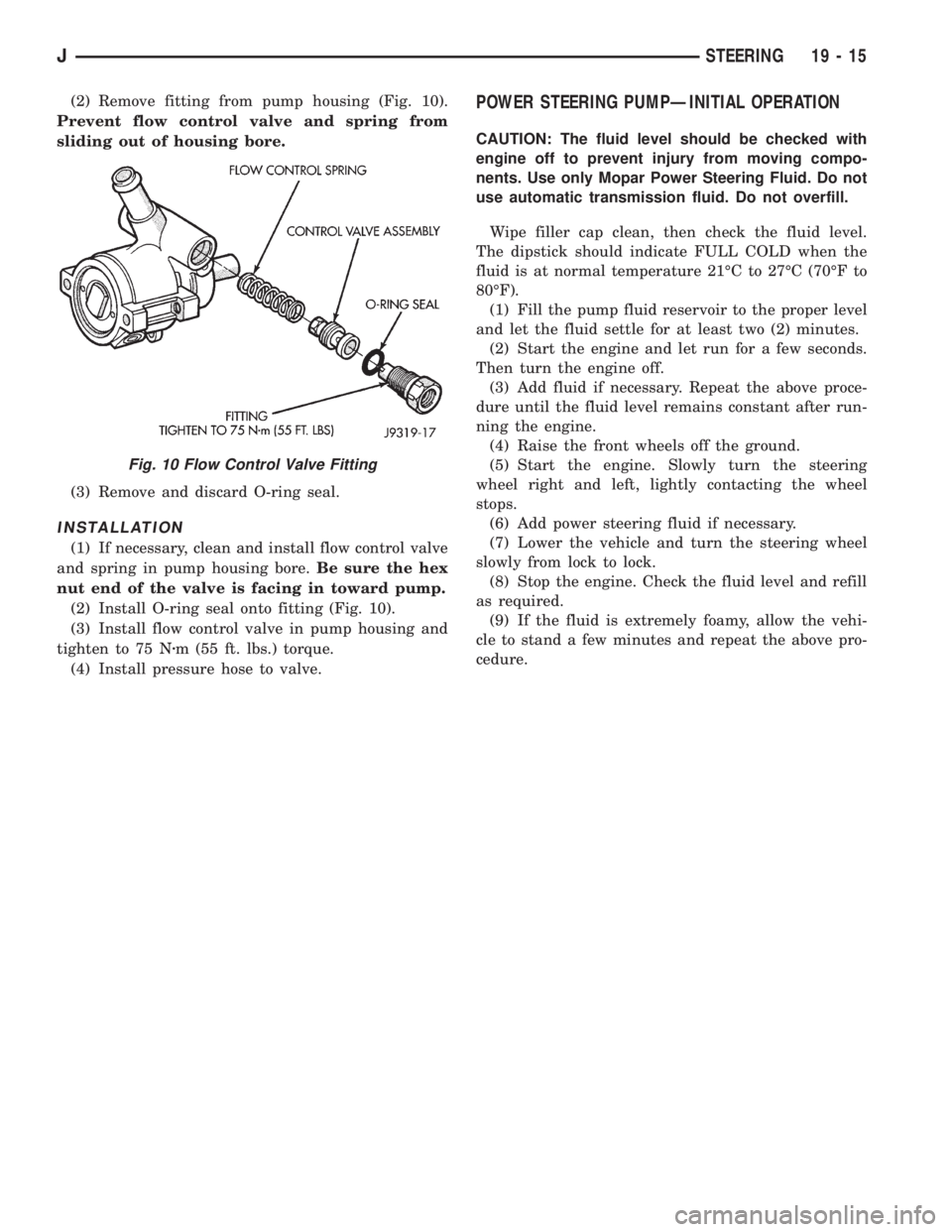
(2) Remove fitting from pump housing (Fig. 10).
Prevent flow control valve and spring from
sliding out of housing bore.
(3) Remove and discard O-ring seal.
INSTALLATION
(1) If necessary, clean and install flow control valve
and spring in pump housing bore.Be sure the hex
nut end of the valve is facing in toward pump.
(2) Install O-ring seal onto fitting (Fig. 10).
(3) Install flow control valve in pump housing and
tighten to 75 Nzm (55 ft. lbs.) torque.
(4) Install pressure hose to valve.
POWER STEERING PUMPÐINITIAL OPERATION
CAUTION: The fluid level should be checked with
engine off to prevent injury from moving compo-
nents. Use only Mopar Power Steering Fluid. Do not
use automatic transmission fluid. Do not overfill.
Wipe filler cap clean, then check the fluid level.
The dipstick should indicate FULL COLD when the
fluid is at normal temperature 21ÉC to 27ÉC (70ÉF to
80ÉF).
(1) Fill the pump fluid reservoir to the proper level
and let the fluid settle for at least two (2) minutes.
(2) Start the engine and let run for a few seconds.
Then turn the engine off.
(3) Add fluid if necessary. Repeat the above proce-
dure until the fluid level remains constant after run-
ning the engine.
(4) Raise the front wheels off the ground.
(5) Start the engine. Slowly turn the steering
wheel right and left, lightly contacting the wheel
stops.
(6) Add power steering fluid if necessary.
(7) Lower the vehicle and turn the steering wheel
slowly from lock to lock.
(8) Stop the engine. Check the fluid level and refill
as required.
(9) If the fluid is extremely foamy, allow the vehi-
cle to stand a few minutes and repeat the above pro-
cedure.
Fig. 10 Flow Control Valve Fitting
JSTEERING 19 - 15
Page 1328 of 2198
CAUTION: Do not turn stub shaft any farther than
necessary. The recirculating balls will drop out of
the rack piston circuit and fall inside the rack pis-
ton chamber.
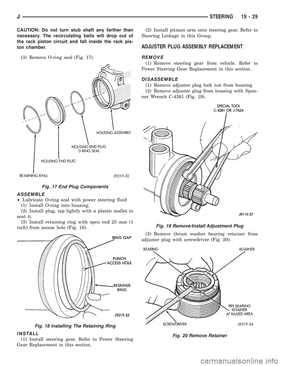
(3) Remove O-ring seal (Fig. 17).
ASSEMBLE
²Lubricate O-ring seal with power steering fluid
(1) Install O-ring into housing.
(2) Install plug, tap lightly with a plastic mallet to
seat it.
(3) Install retaining ring with open end 25 mm (1
inch) from access hole (Fig. 18).
INSTALL
(1) Install steering gear. Refer to Power Steering
Gear Replacement in this section.(2) Install pitman arm onto steering gear. Refer to
Steering Linkage in this Group.
ADJUSTER PLUG ASSEMBLY REPLACEMENT
REMOVE
(1) Remove steering gear from vehicle. Refer to
Power Steering Gear Replacement in this section.
DISASSEMBLE
(1) Remove adjuster plug lock nut from housing.
(2) Remove adjuster plug from housing with Span-
ner Wrench C-4381 (Fig. 19).
(3) Remove thrust washer bearing retainer from
adjuster plug with screwdriver (Fig. 20).
Fig. 17 End Plug Components
Fig. 18 Installing The Retaining Ring
Fig. 19 Remove/Install Adjustment Plug
Fig. 20 Remove Retainer
JSTEERING 19 - 29
Page 1330 of 2198
DISASSEMBLE
(1) Remove adjuster plug, refer to Adjuster Plug
Assembly Replacement.
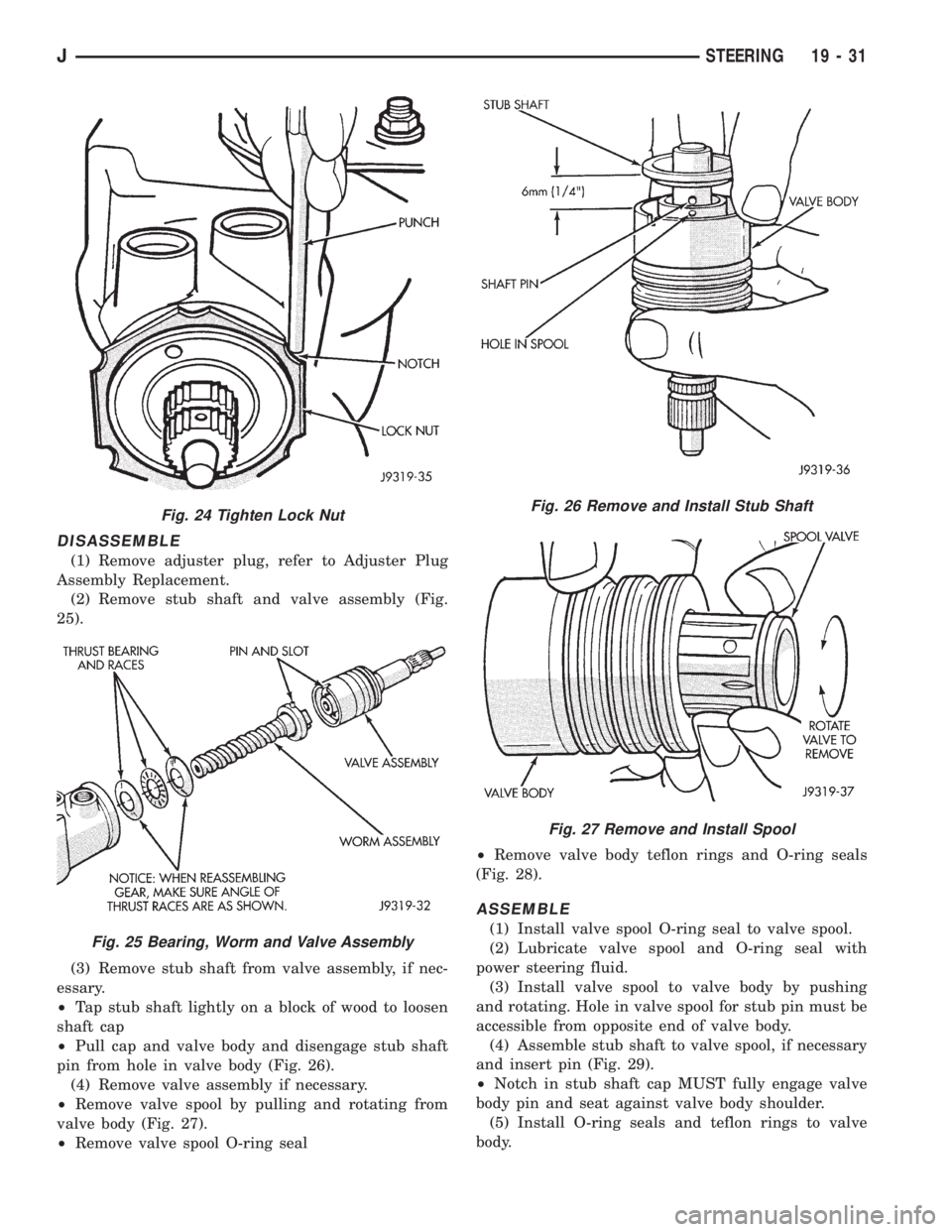
(2) Remove stub shaft and valve assembly (Fig.
25).
(3) Remove stub shaft from valve assembly, if nec-
essary.
²Tap stub shaft lightly on a block of wood to loosen
shaft cap
²Pull cap and valve body and disengage stub shaft
pin from hole in valve body (Fig. 26).
(4) Remove valve assembly if necessary.
²Remove valve spool by pulling and rotating from
valve body (Fig. 27).
²Remove valve spool O-ring seal²Remove valve body teflon rings and O-ring seals
(Fig. 28).
ASSEMBLE
(1) Install valve spool O-ring seal to valve spool.
(2) Lubricate valve spool and O-ring seal with
power steering fluid.
(3) Install valve spool to valve body by pushing
and rotating. Hole in valve spool for stub pin must be
accessible from opposite end of valve body.
(4) Assemble stub shaft to valve spool, if necessary
and insert pin (Fig. 29).
²Notch in stub shaft cap MUST fully engage valve
body pin and seat against valve body shoulder.
(5) Install O-ring seals and teflon rings to valve
body.
Fig. 24 Tighten Lock Nut
Fig. 25 Bearing, Worm and Valve Assembly
Fig. 26 Remove and Install Stub Shaft
Fig. 27 Remove and Install Spool
JSTEERING 19 - 31
Page 1332 of 2198
CLEAN AND INSPECTION
(1) Wash all components in clean solvent and dry
with compressed air.
(2) Check for scores, nicks or burrs on the rack pis-
ton finished surface. Slight wear is normal on the
worm gear surfaces.
ASSEMBLE
(1) Install O-ring seal and teflon ring and lubricate
with power steering fluid.
(2) Install worm shaft to rack piston outside of
housing. Fully seat worm shaft to rack piston and
align worm shaft spiral groove with rack piston ball
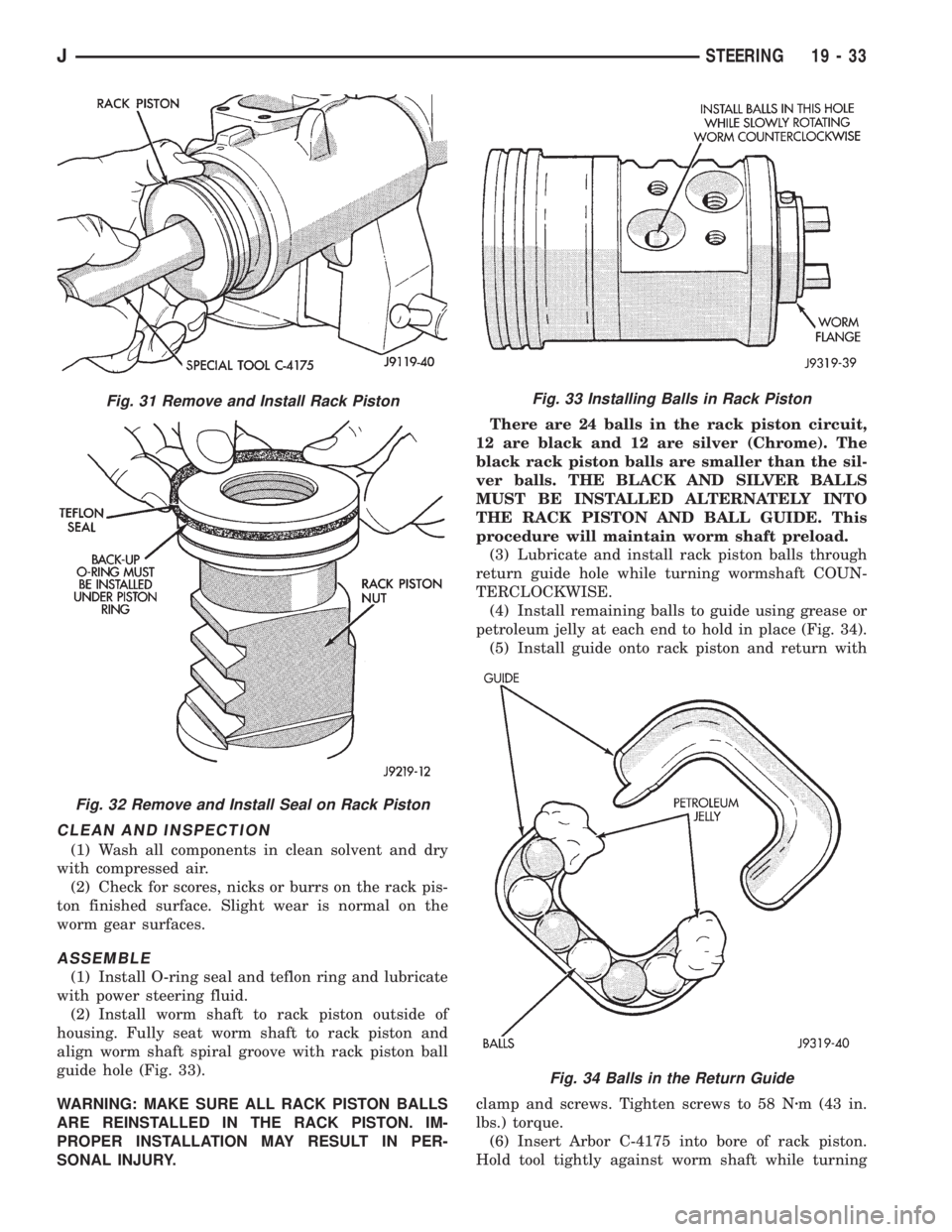
guide hole (Fig. 33).
WARNING: MAKE SURE ALL RACK PISTON BALLS
ARE REINSTALLED IN THE RACK PISTON. IM-
PROPER INSTALLATION MAY RESULT IN PER-
SONAL INJURY.There are 24 balls in the rack piston circuit,
12 are black and 12 are silver (Chrome). The
black rack piston balls are smaller than the sil-
ver balls. THE BLACK AND SILVER BALLS
MUST BE INSTALLED ALTERNATELY INTO
THE RACK PISTON AND BALL GUIDE. This
procedure will maintain worm shaft preload.
(3) Lubricate and install rack piston balls through
return guide hole while turning wormshaft COUN-
TERCLOCKWISE.
(4) Install remaining balls to guide using grease or
petroleum jelly at each end to hold in place (Fig. 34).
(5) Install guide onto rack piston and return with
clamp and screws. Tighten screws to 58 Nzm (43 in.
lbs.) torque.
(6) Insert Arbor C-4175 into bore of rack piston.
Hold tool tightly against worm shaft while turning
Fig. 31 Remove and Install Rack Piston
Fig. 32 Remove and Install Seal on Rack Piston
Fig. 33 Installing Balls in Rack Piston
Fig. 34 Balls in the Return Guide
JSTEERING 19 - 33
Page 1340 of 2198
(3) Hold the ball nut over a cloth. Remove the re-
maining recirculating balls by rotating the worm-
shaft back and forth.
There are a total of 50 recirculating balls
within the ball nut and the guides (25 in each
circuit).
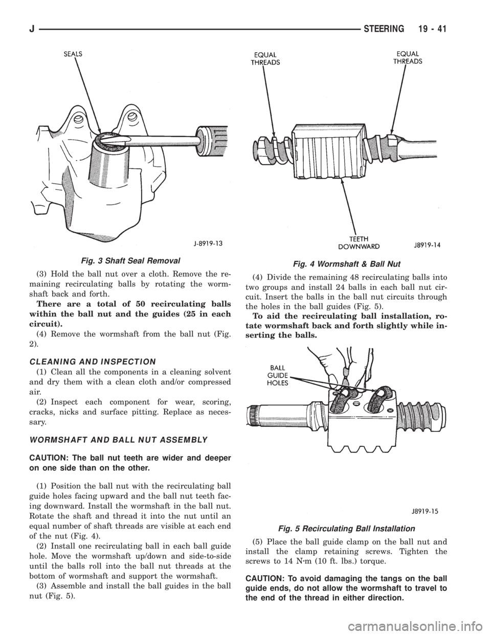
(4) Remove the wormshaft from the ball nut (Fig.
2).
CLEANING AND INSPECTION
(1) Clean all the components in a cleaning solvent
and dry them with a clean cloth and/or compressed
air.
(2) Inspect each component for wear, scoring,
cracks, nicks and surface pitting. Replace as neces-
sary.
WORMSHAFT AND BALL NUT ASSEMBLY
CAUTION: The ball nut teeth are wider and deeper
on one side than on the other.
(1) Position the ball nut with the recirculating ball
guide holes facing upward and the ball nut teeth fac-
ing downward. Install the wormshaft in the ball nut.
Rotate the shaft and thread it into the nut until an
equal number of shaft threads are visible at each end
of the nut (Fig. 4).
(2) Install one recirculating ball in each ball guide
hole. Move the wormshaft up/down and side-to-side
until the balls roll into the ball nut threads at the
bottom of wormshaft and support the wormshaft.
(3) Assemble and install the ball guides in the ball
nut (Fig. 5).(4) Divide the remaining 48 recirculating balls into
two groups and install 24 balls in each ball nut cir-
cuit. Insert the balls in the ball nut circuits through
the holes in the ball guides (Fig. 5).
To aid the recirculating ball installation, ro-
tate wormshaft back and forth slightly while in-
serting the balls.
(5) Place the ball guide clamp on the ball nut and
install the clamp retaining screws. Tighten the
screws to 14 Nzm (10 ft. lbs.) torque.
CAUTION: To avoid damaging the tangs on the ball
guide ends, do not allow the wormshaft to travel to
the end of the thread in either direction.
Fig. 3 Shaft Seal RemovalFig. 4 Wormshaft & Ball Nut
Fig. 5 Recirculating Ball Installation
JSTEERING 19 - 41