1995 JEEP CHEROKEE turn signal and hazard
[x] Cancel search: turn signal and hazardPage 417 of 2198
lamps and repair circuits or replace bulbs as re-
quired. If system still does not function properly, pro-
ceed as follows.
(1) Locate fuseblock module under driver's side of
instrument panel. Remove and inspect fuse 4. If OK,
go to next step. If not OK, replace fuse as required.
(2) Replace turn signal flasher (light blue can in
fuseblock module) with a known good unit. Test op-
eration. If OK, replace faulty turn signal flasher. If
not OK, remove test flasher and go to next step.
(3) Turn ignition switch to ACCESSORY position.
Check for battery voltage at flasher cavity on left
(closest to hazard flasher). If OK, go to next step. If
not OK, repair circuit to fuse 4 as required.
(4) Turn ignition switch to OFF position. See Turn
Signal/Hazard Warning Switch Remove/Install to lo-
cate steering column connector. Unplug connector.
(5) Turn ignition switch to ACCESSORY position.
Check for battery voltage at connector terminal L. If
OK, replace turn signal/hazard warning switch. If not
OK, repair circuit between turn signal flasher and
steering column connector.
HAZARD WARNING SYSTEM - YJ
(1) Locate Power Distribution Center (PDC) near
battery tray in engine compartment. Remove and in-
spect fuse F5. If OK, go to next step. If not OK,
replace fuse as required.(2) Replace hazard warning flasher (metal can in
fuseblock module) with a known good unit. Test op-
eration. If OK, replace faulty hazard warning flasher.
If not OK, remove test flasher and go to next step.
(3) Check for battery voltage at flasher cavity on
left (closest to hazard flasher). If OK, go to next step.
If not OK, repair circuit to fuse F5 in PDC as re-
quired.
(4) See Turn Signal/Hazard Warning Switch Re-
move/Install to locate steering column connector. Un-
plug connector.
(5) Check for battery voltage at connector terminal
K. If OK, replace turn signal/hazard warning switch.
If not OK, repair circuit between hazard warning
flasher and steering column connector.
MULTI-FUNCTION SWITCH - XJ
(1) Access multi-function switch connector and re-
move. See service procedures for Multi-Function
Switch, in this group.
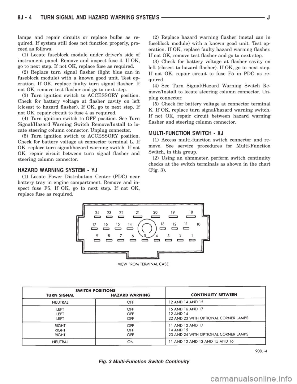
(2) Using an ohmmeter, perform switch continuity
checks at the switch terminals as shown in the chart
(Fig. 3).
Fig. 3 Multi-Function Switch Continuity
8J - 4 TURN SIGNAL AND HAZARD WARNING SYSTEMSJ
Page 418 of 2198
SERVICE PROCEDURES
WARNING: ON VEHICLES EQUIPPED WITH AN AIRBAG,
REFER TO GROUP 8M - RESTRAINT SYSTEMS BEFORE
ATTEMPTING STEERING WHEEL COMPONENT DIAGNO-
SIS OR SERVICE. FAILURE TO TAKE PROPER PRECAU-
TIONS COULD RESULT IN ACCIDENTAL AIRBAG DE-
PLOYMENT AND POSSIBLE PERSONAL INJURY.
MULTI-FUNCTION SWITCH REMOVE/INSTALL - XJ
(1) Disconnect battery negative cable.
(2) Remove tilt lever (if equipped).
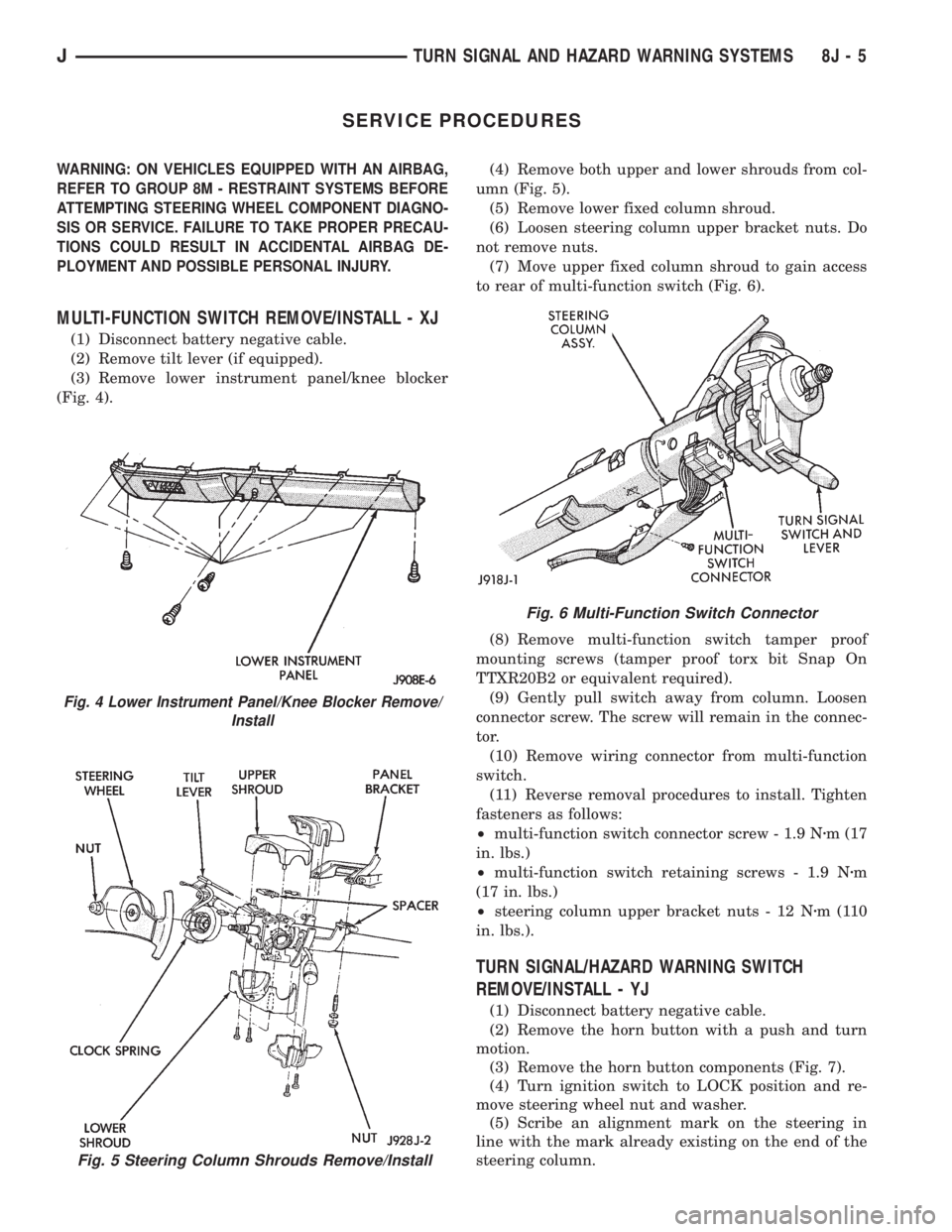
(3) Remove lower instrument panel/knee blocker
(Fig. 4).(4) Remove both upper and lower shrouds from col-
umn (Fig. 5).
(5) Remove lower fixed column shroud.
(6) Loosen steering column upper bracket nuts. Do
not remove nuts.
(7) Move upper fixed column shroud to gain access
to rear of multi-function switch (Fig. 6).
(8) Remove multi-function switch tamper proof
mounting screws (tamper proof torx bit Snap On
TTXR20B2 or equivalent required).
(9) Gently pull switch away from column. Loosen
connector screw. The screw will remain in the connec-
tor.
(10) Remove wiring connector from multi-function
switch.
(11) Reverse removal procedures to install. Tighten
fasteners as follows:
²multi-function switch connector screw - 1.9 Nzm (17
in. lbs.)
²multi-function switch retaining screws - 1.9 Nzm
(17 in. lbs.)
²steering column upper bracket nuts - 12 Nzm(110
in. lbs.).
TURN SIGNAL/HAZARD WARNING SWITCH
REMOVE/INSTALL - YJ
(1) Disconnect battery negative cable.
(2) Remove the horn button with a push and turn
motion.
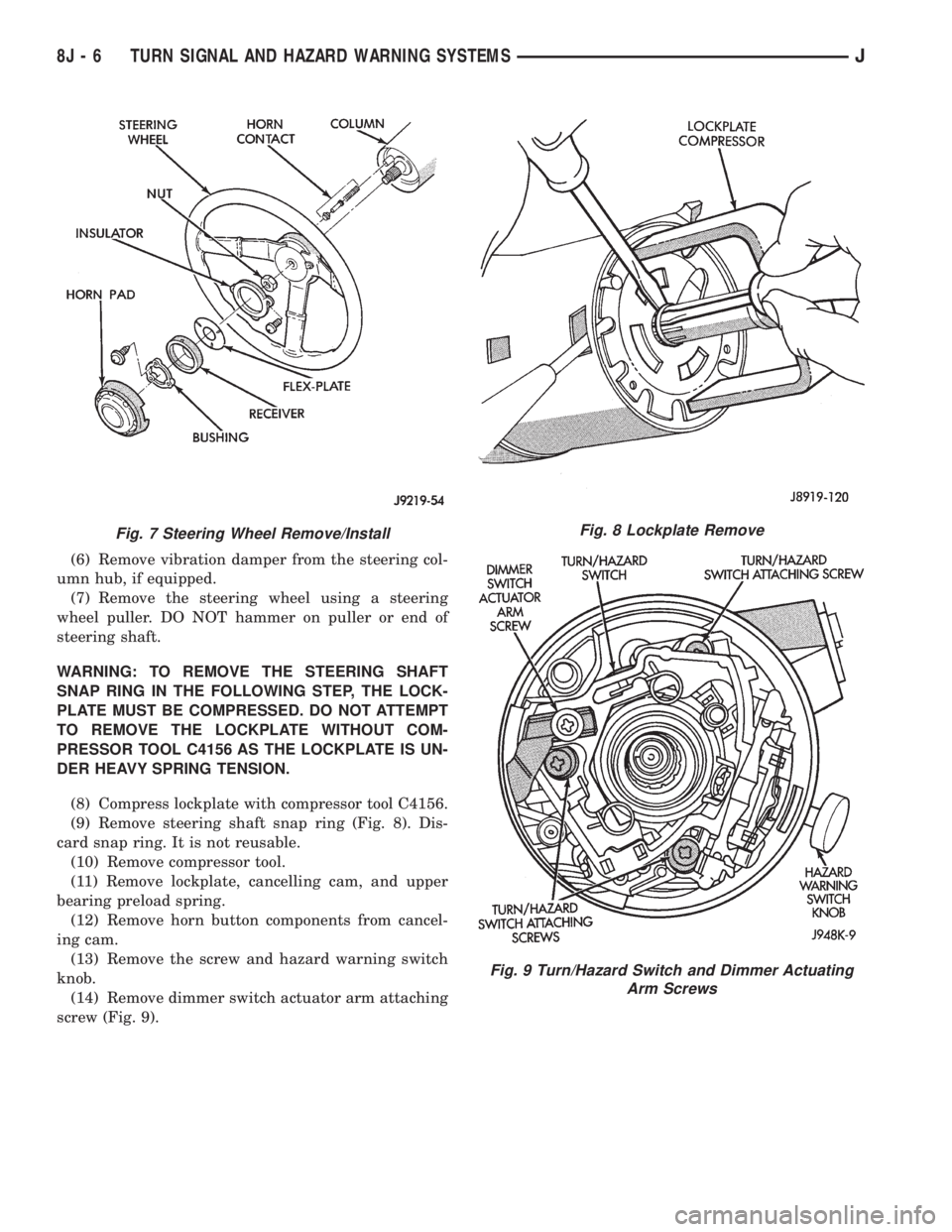
(3) Remove the horn button components (Fig. 7).
(4) Turn ignition switch to LOCK position and re-
move steering wheel nut and washer.
(5) Scribe an alignment mark on the steering in
line with the mark already existing on the end of the
steering column.
Fig. 5 Steering Column Shrouds Remove/Install
Fig. 4 Lower Instrument Panel/Knee Blocker Remove/
Install
Fig. 6 Multi-Function Switch Connector
JTURN SIGNAL AND HAZARD WARNING SYSTEMS 8J - 5
Page 419 of 2198
(6) Remove vibration damper from the steering col-
umn hub, if equipped.
(7) Remove the steering wheel using a steering
wheel puller. DO NOT hammer on puller or end of
steering shaft.
WARNING: TO REMOVE THE STEERING SHAFT
SNAP RING IN THE FOLLOWING STEP, THE LOCK-
PLATE MUST BE COMPRESSED. DO NOT ATTEMPT
TO REMOVE THE LOCKPLATE WITHOUT COM-
PRESSOR TOOL C4156 AS THE LOCKPLATE IS UN-
DER HEAVY SPRING TENSION.
(8) Compress lockplate with compressor tool C4156.
(9) Remove steering shaft snap ring (Fig. 8). Dis-
card snap ring. It is not reusable.
(10) Remove compressor tool.
(11) Remove lockplate, cancelling cam, and upper
bearing preload spring.
(12) Remove horn button components from cancel-
ing cam.
(13) Remove the screw and hazard warning switch
knob.
(14) Remove dimmer switch actuator arm attaching
screw (Fig. 9).
Fig. 7 Steering Wheel Remove/InstallFig. 8 Lockplate Remove
Fig. 9 Turn/Hazard Switch and Dimmer Actuating
Arm Screws
8J - 6 TURN SIGNAL AND HAZARD WARNING SYSTEMSJ
Page 420 of 2198

(15) Remove turn/hazard switch attaching screws.
(16) Remove 6 housing screws (Fig. 10).
(17) Slide housing toward steering wheel.
(18) Remove cover under column.
(19) If vehicle is equipped with a column shift,
remove PRNDL cable clip (Fig. 11).(20) Remove 2 nuts holding steering column
bracket to brake sled (Fig. 12).
(21) Remove 4 bolts holding steering column
bracket to column.
(22) Loosen column brace mounting nut at drivers
side kick panel. This will allow column to drop.
(23) Push turn/hazard connector up and out of
steering column connector (Fig. 13).
Fig. 10 Instrument Housing Remove/Install
Fig. 11 PRNDL Cable Clip Remove/Install
Fig. 12 Lower Steering Column
Fig. 13 Turn/Hazard Switch and Steering Column
Connectors
JTURN SIGNAL AND HAZARD WARNING SYSTEMS 8J - 7
Page 421 of 2198

(24) Pry up locking tabs of steering column connec-
tor and remove connector from column bracket.
(25) Tape connector to wires as shown (Fig. 14).
(26) Remove plastic harness cover by pulling it up
and over the weld nuts then open and slide the cover
off the harness (Fig. 15).
(27) Remove the turn/hazard switch. Pull the
switch and wire harness straight up and out of the
housing.(28) To install a new switch, reverse the removal
procedure.
CAUTION: When installing a turn/hazard switch,
make sure wires are laying flat on bottom inside
column.
On vehicles equipped with column shift, in-
stall the PRNDL cable clip with the shift indica-
tor on N (neutral). Move the selector through
the range and make sure it lines up with each
letter.
(29) Adjust the headlamp dimmer switch as de-
scribed in Group 8L - Lamps.
Fig. 15 Remove Plastic Harness Cover
Fig. 14 Tape Wiper Switch Connector
8J - 8 TURN SIGNAL AND HAZARD WARNING SYSTEMSJ
Page 451 of 2198
MULTI-FUNCTION SWITCH TESTING
PROCEDURESÐXJ
The multi-function switch contains electrical cir-
cuitry for:
²Headlamp Dimmer Switch.
²Passing Lights.
²Turn Signals.
²Hazard Warning.
²Windshield Wiper.
²Pulse Wiper.
²Windshield Washer.
This integrated switch is mounted to the left hand
side of the steering column. Should any function of
the switch fail, the entire switch must be replaced.
The multi-function switch also serves as a fog lamp
lock-out circuit. The circuit to the fog lamp switch is
completed only when the dimmer switch is in the low
beam position.
SWITCH TEST
(1) Disconnect battery negative cable.
(2) Remove lower instrument panel screws along
bottom edge of steering column (Fig. 1).
(3) Remove lower instrument panel/knee blocker.
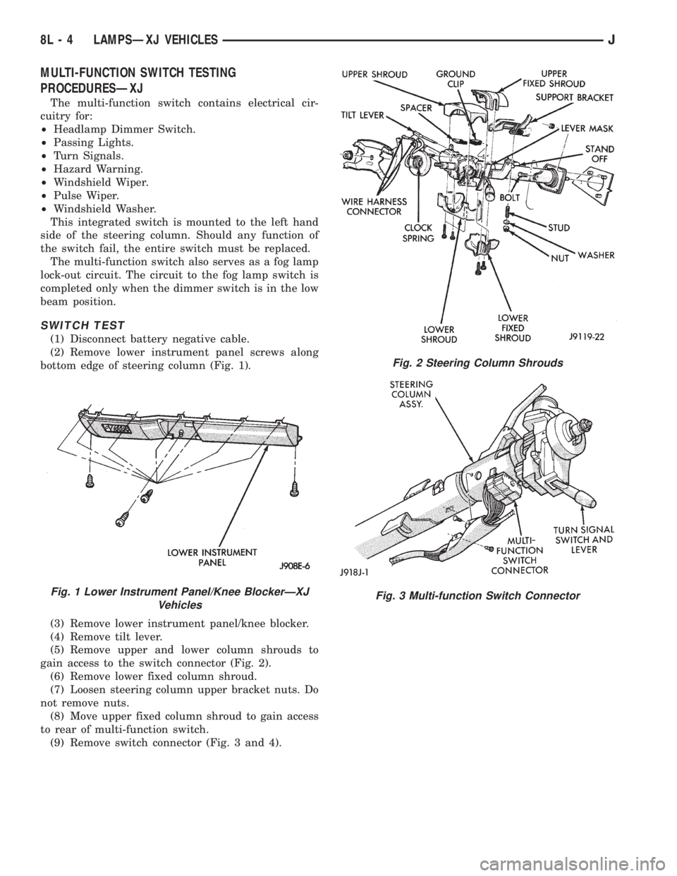
(4) Remove tilt lever.
(5) Remove upper and lower column shrouds to
gain access to the switch connector (Fig. 2).
(6) Remove lower fixed column shroud.
(7) Loosen steering column upper bracket nuts. Do
not remove nuts.
(8) Move upper fixed column shroud to gain access
to rear of multi-function switch.
(9) Remove switch connector (Fig. 3 and 4).
Fig. 1 Lower Instrument Panel/Knee BlockerÐXJ
Vehicles
Fig. 2 Steering Column Shrouds
Fig. 3 Multi-function Switch Connector
8L - 4 LAMPSÐXJ VEHICLESJ
Page 479 of 2198

BULB APPLICATIONÐYJ VEHICLES
GENERAL INFORMATION
The following Bulb Application Table lists the lamp
title on the left side of the column and trade number
or part number on the right.
CAUTION: Do not use bulbs that have a higher can-
dle power than the bulb listed in the Bulb Applica-
tion Table. Damage to lamp can result.
Do not touch halogen bulbs with fingers or other
oily surfaces. Bulb life will be reduced.
EXTERIOR LAMPSÐYJ
Back-up .................................................................1156
Center High Mounted Stoplamp ..........................912
Fog ............................................................................H3
Front Side Marker .................................................194
Headlamp/Sealed Beam....................................H6054
Park/Turn Signal..................................................3157
Tail/Stop ................................................................1157
INTERIOR LAMPSÐYJ
Service procedures for most of the lamps in the in-
strument panel, Instrument cluster and switches are
located in Group 8E, Instrument Panel and Gauges.
Some components have lamps that can only be ser-
viced by an Authorized Service Center (ASC) after
the component is removed from the vehicle. Contact
local dealer for location of nearest ASC.Dome/Cargo .........................................................212-2
Glove Compartment ...............................................194
Under Hood ............................................................105
Underpanel Courtesy...............................................89
INDICATOR LAMPS
Service procedures for most of the lamps in the in-
strument panel, instrument cluster and switches are
located in Group 8E, Instrument Panel and Gauges.
A/C Control ...............................................................74
Anti-lock Brake ........................................................74
Ash Receiver .........................................................1891
Brake Warning .........................................................74
Cigar Lighter ............................................................53
Fasten Seat Belts ....................................................74
Four Wheel Drive ....................................................74
Generator ................................................................194
Hazard.......................................................................74
Heater Control .......................................................194
High Beam..............................................................194
Illumination ............................................................194
Low Coolant..............................................................74
Radio ......................................................................ASC
Rocker Switch...........................................................74
Seat Belt ...................................................................74
Shift ...........................................................................74
Turn Signal.............................................................194
8L - 32 LAMPSÐYJ VEHICLESJ
Page 676 of 2198
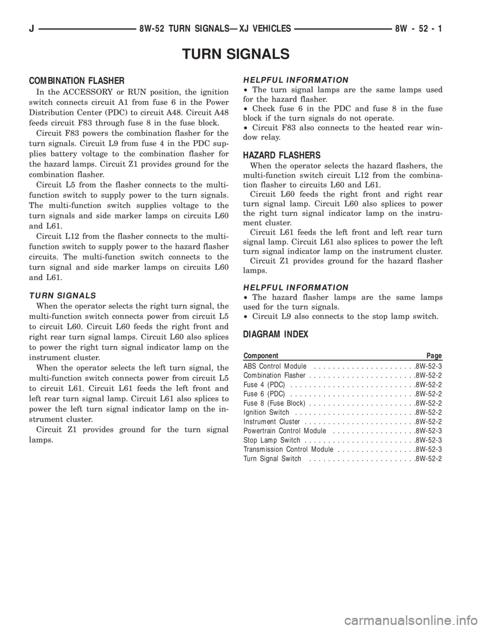
TURN SIGNALS
COMBINATION FLASHER
In the ACCESSORY or RUN position, the ignition
switch connects circuit A1 from fuse 6 in the Power
Distribution Center (PDC) to circuit A48. Circuit A48
feeds circuit F83 through fuse 8 in the fuse block.
Circuit F83 powers the combination flasher for the
turn signals. Circuit L9 from fuse 4 in the PDC sup-
plies battery voltage to the combination flasher for
the hazard lamps. Circuit Z1 provides ground for the
combination flasher.
Circuit L5 from the flasher connects to the multi-
function switch to supply power to the turn signals.
The multi-function switch supplies voltage to the
turn signals and side marker lamps on circuits L60
and L61.
Circuit L12 from the flasher connects to the multi-
function switch to supply power to the hazard flasher
circuits. The multi-function switch connects to the
turn signal and side marker lamps on circuits L60
and L61.
TURN SIGNALS
When the operator selects the right turn signal, the
multi-function switch connects power from circuit L5
to circuit L60. Circuit L60 feeds the right front and
right rear turn signal lamps. Circuit L60 also splices
to power the right turn signal indicator lamp on the
instrument cluster.
When the operator selects the left turn signal, the
multi-function switch connects power from circuit L5
to circuit L61. Circuit L61 feeds the left front and
left rear turn signal lamp. Circuit L61 also splices to
power the left turn signal indicator lamp on the in-
strument cluster.
Circuit Z1 provides ground for the turn signal
lamps.
HELPFUL INFORMATION
²The turn signal lamps are the same lamps used
for the hazard flasher.
²Check fuse 6 in the PDC and fuse 8 in the fuse
block if the turn signals do not operate.
²Circuit F83 also connects to the heated rear win-
dow relay.
HAZARD FLASHERS
When the operator selects the hazard flashers, the
multi-function switch circuit L12 from the combina-
tion flasher to circuits L60 and L61.
Circuit L60 feeds the right front and right rear
turn signal lamp. Circuit L60 also splices to power
the right turn signal indicator lamp on the instru-
ment cluster.
Circuit L61 feeds the left front and left rear turn
signal lamp. Circuit L61 also splices to power the left
turn signal indicator lamp on the instrument cluster.
Circuit Z1 provides ground for the hazard flasher
lamps.
HELPFUL INFORMATION
²The hazard flasher lamps are the same lamps
used for the turn signals.
²Circuit L9 also connects to the stop lamp switch.
DIAGRAM INDEX
Component Page
ABS Control Module......................8W-52-3
Combination Flasher.......................8W-52-2
Fuse 4 (PDC)...........................8W-52-2
Fuse 6 (PDC)...........................8W-52-2
Fuse 8 (Fuse Block).......................8W-52-2
Ignition Switch..........................8W-52-2
Instrument Cluster........................8W-52-2
Powertrain Control Module..................8W-52-3
Stop Lamp Switch........................8W-52-3
Transmission Control Module.................8W-52-3
Turn Signal Switch.......................8W-52-2
J8W-52 TURN SIGNALSÐXJ VEHICLES 8W - 52 - 1