1995 JEEP CHEROKEE towing
[x] Cancel search: towingPage 15 of 2198

(3) Cover the open end of the transmission exten-
sion housing.
4WD VEHICLESÐXJ
(1) Shift transfer case lever to NEUTRAL.
(2) Place ignition switch in the unlocked position.
4WD VEHICLESÐYJ
CAUTION: Follow these steps to be certain that the
transfer case is fully in N (NEUTRAL) and that the
axle is completely disengaged before flat towing to
prevent damage to internal parts.
(1) Shift transfer case into 2H and check that the
4WD light goes out.
(2) Start engine and drive the vehicle 3 mm (10 ft.)
rearward and then 3 mm (10 ft.) forward to make
sure the axle is disengaged.(3) Shift transmission to Neutral.
(4) Turn off engine with the ignition key in the un-
locked OFF position.
(5) Shift transfer case lever from 2H to N (NEU-
TRAL) position.
(6) Shift manual transmission into gear or auto-
matic transmission into P (PARK).
WARNING: WITH THE TRANSFER CASE IN NEU-
TRAL POSITION, THE VEHICLE COULD ROLL UN-
EXPECTEDLY. THE PARKING BRAKE SHOULD
ALWAYS BE APPLIED BEFORE THE TOW BAR IS
ATTACHED.
(7) Attach vehicle to the tow vehicle with tow bar.
CAUTION: Do not use a bumper mounted clamp-on
tow bar, damage to bumper face bar may occur.
0 - 14 LUBRICATION AND MAINTENANCEJ
Page 25 of 2198
SPECIAL ADDITIVES
The addition of any special-type fluid to a Jeep au-
tomatic transmission is not recommended. The only
exception is the addition of black-light detection dye
to aid in detecting the source of ATF leaks. The use
of transmission sealing additives should also be
avoided.
Black-light detection dye is factory-installed
in automatic transmissions and, unless the ATF
has been drained and re-placed, it is not neces-
sary to add dye.
FLUID AND FILTER CHANGE
The automatic transmission fluid and filter should
be changed at the intervals described in the Mainte-
nance Schedules section of this Group. Refer to
Group 21, Transmission for proper service proce-
dures.
TRANSFER CASE (4WD VEHICLES)
The transfer case should be inspected for fluid
leaks and proper fluid level when other under vehicle
service is performed.
FLUID LEVEL
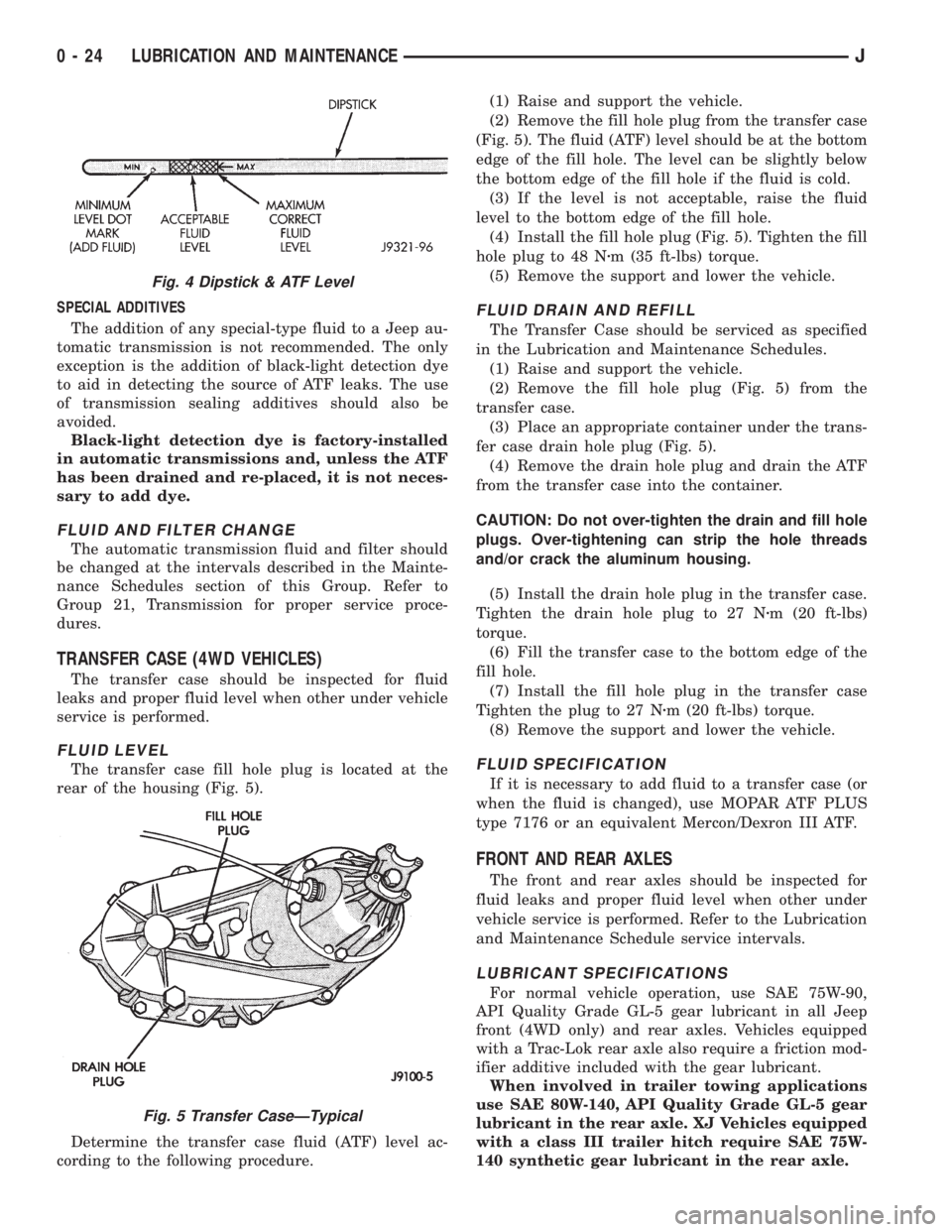
The transfer case fill hole plug is located at the
rear of the housing (Fig. 5).
Determine the transfer case fluid (ATF) level ac-
cording to the following procedure.(1) Raise and support the vehicle.
(2) Remove the fill hole plug from the transfer case
(Fig. 5). The fluid (ATF) level should be at the bottom
edge of the fill hole. The level can be slightly below
the bottom edge of the fill hole if the fluid is cold.
(3) If the level is not acceptable, raise the fluid
level to the bottom edge of the fill hole.
(4) Install the fill hole plug (Fig. 5). Tighten the fill
hole plug to 48 Nzm (35 ft-lbs) torque.
(5) Remove the support and lower the vehicle.
FLUID DRAIN AND REFILL
The Transfer Case should be serviced as specified
in the Lubrication and Maintenance Schedules.
(1) Raise and support the vehicle.
(2) Remove the fill hole plug (Fig. 5) from the
transfer case.
(3) Place an appropriate container under the trans-
fer case drain hole plug (Fig. 5).
(4) Remove the drain hole plug and drain the ATF
from the transfer case into the container.
CAUTION: Do not over-tighten the drain and fill hole
plugs. Over-tightening can strip the hole threads
and/or crack the aluminum housing.
(5) Install the drain hole plug in the transfer case.
Tighten the drain hole plug to 27 Nzm (20 ft-lbs)
torque.
(6) Fill the transfer case to the bottom edge of the
fill hole.
(7) Install the fill hole plug in the transfer case
Tighten the plug to 27 Nzm (20 ft-lbs) torque.
(8) Remove the support and lower the vehicle.
FLUID SPECIFICATION
If it is necessary to add fluid to a transfer case (or
when the fluid is changed), use MOPAR ATF PLUS
type 7176 or an equivalent Mercon/Dexron III ATF.
FRONT AND REAR AXLES
The front and rear axles should be inspected for
fluid leaks and proper fluid level when other under
vehicle service is performed. Refer to the Lubrication
and Maintenance Schedule service intervals.
LUBRICANT SPECIFICATIONS
For normal vehicle operation, use SAE 75W-90,
API Quality Grade GL-5 gear lubricant in all Jeep
front (4WD only) and rear axles. Vehicles equipped
with a Trac-Lok rear axle also require a friction mod-
ifier additive included with the gear lubricant.
When involved in trailer towing applications
use SAE 80W-140, API Quality Grade GL-5 gear
lubricant in the rear axle. XJ Vehicles equipped
with a class III trailer hitch require SAE 75W-
140 synthetic gear lubricant in the rear axle.
Fig. 4 Dipstick & ATF Level
Fig. 5 Transfer CaseÐTypical
0 - 24 LUBRICATION AND MAINTENANCEJ
Page 53 of 2198

AXLE NOISE/VIBRATION DIAGNOSIS
INDEX
page page
Driveline Snap........................... 19
Gear and Bearing Noise.................... 18
General Information....................... 18Low Speed Knock......................... 19
Vibration................................ 19
GENERAL INFORMATION
Axle bearing problem conditions are usually caused
by:
²Insufficient or incorrect lubricant
²Foreign matter/water contamination
²Incorrect bearing preload torque adjustment
²Incorrect backlash (to tight)
When serviced, the bearings must be cleaned thor-
oughly. They should be dried with lint-free shop tow-
els.Never dry bearings with compressed air.
This will overheat them and brinell the bearing
surfaces. This will result in noisy operation af-
ter repair.
Axle gear problem conditions are usually the result
of:
²Insufficient lubrication
²Incorrect or contaminated lubricant
²Overloading (excessive engine torque) or exceeding
vehicle weight capacity
²Incorrect clearance or backlash adjustment
Insufficient lubrication is usually the result of a
housing cover leak. It can also be from worn axle
shaft or pinion gear seals. Check for cracks or porous
areas in the housing or tubes.
Using the wrong lubricant will cause overheating
and gear failure. Gear tooth cracking and bearing
spalling are indicators of this.
Axle component breakage is most often the result
of:
²Severe overloading
²Insufficient lubricant
²Incorrect lubricant
²Improperly tightened components
Overloading occurs when towing heavier than rec-
ommended loads. Component breakage can occur
when the wheels are spun excessively. Incorrect lu-
bricant quantity contributes to breakage. Loose dif-
ferential components can also cause breakage.
Incorrect bearing preload or gear backlash will not
result in component breakage. Mis-adjustment will
produce enough noise to cause service repair before a
failure occurs. If a mis-adjustment condition is not
corrected, component failure can result.
Excessive bearing preload may not be noisy. This
condition will cause high temperature which can re-
sult in bearing failure.
GEAR AND BEARING NOISE
GEAR NOISE
Axle gear noise can be caused by insufficient lubri-
cant. Incorrect backlash, tooth contact, or worn/dam-
aged gears can cause noise.
Gear noise usually happens at a specific speed
range. The range is 30 to 40 mph, or above 50 mph.
The noise can also occur during a specific type of
driving condition. These conditions are acceleration,
deceleration, coast, or constant load.
When road testing, accelerate the vehicle to the
speed range where the noise is the greatest. Shift
out-of-gear and coast through the peak-noise range.
If the noise stops or changes greatly, check for insuf-
ficient lubricant. Incorrect ring gear backlash, or
gear damage can cause noise changes.
Differential side and pinion gears can be checked
by turning the vehicle. They usually do not cause
noise in straight-ahead driving. These gears are
loaded during vehicle turns. If noise does occur dur-
ing vehicle turns, the side or pinion gears could be
worn or damaged. A worn pinion gear mate shaft can
also cause a snapping or a knocking noise.
BEARING NOISE
The axle shaft, differential and pinion gear bear-
ings can all produce noise when worn or damaged.
Bearing noise can be either a whining, or a growling
sound.
Pinion gear bearings have a constant-pitch noise.
This noise changes only with vehicle speed. Pinion
bearing noise will be higher because it rotates at a
faster rate. Drive the vehicle and load the differen-
tial. If bearing noise occurs the pinion rear bearing is
the source of the noise. If the bearing noise is heard
during a coast, front bearing is the source.
Worn, damaged differential bearings usually pro-
duce a low pitch noise. Differential bearing noise is
similar to pinion bearing. The pitch of differential
bearing noise is also constant and varies only with
vehicle speed.
2 - 18 FRONT SUSPENSION AND AXLEJ
Page 94 of 2198
AXLE NOISE/VIBRATION DIAGNOSIS
INDEX
page page
Driveline Snap........................... 10
Gear and Bearing Noise..................... 9
General Information........................ 9
Limited Slip Differential..................... 10Low Speed Knock......................... 10
Rear Axle Alignment....................... 10
Vibration................................ 10
GENERAL INFORMATION
Axle bearing problem conditions are usually caused
by:
²Insufficient or incorrect lubricant
²Foreign matter/water contamination
²Incorrect bearing preload torque adjustment
²Incorrect backlash (to tight)
When serviced, the bearings must be cleaned thor-
oughly. They should be dried with lint-free shop tow-
els.Never dry bearings with compressed air.
This will overheat them and brinell the bearing
surfaces. This will result in noisy operation af-
ter repair.
Axle gear problem conditions are usually the result of:
²Insufficient lubrication
²Incorrect or contaminated lubricant
²Overloading (excessive engine torque) or exceeding
vehicle weight capacity
²Incorrect clearance or backlash adjustment
Insufficient lubrication is usually the result of a
housing cover leak. It can also be from worn axle
shaft or pinion gear seals. Check for cracks or porous
areas in the housing or tubes.
Using the wrong lubricant will cause overheating
and gear failure. Gear tooth cracking and bearing
spalling are indicators of this.
Axle component breakage is most often the result of:
²Severe overloading
²Insufficient lubricant
²Incorrect lubricant
²Improperly tightened components
Overloading occurs when towing heavier than rec-
ommended loads. Component breakage can occur
when the wheels are spun excessively. Incorrect lu-
bricant quantity contributes to breakage. Loose dif-
ferential components can also cause breakage.
Incorrect bearing preload or gear backlash will not
result in component breakage. Mis-adjustment will
produce enough noise to cause service repair before a
failure occurs. If a mis-adjustment condition is not
corrected, component failure can result.
Excessive bearing preload may not be noisy. This
condition will cause high temperature which can re-
sult in bearing failure.
GEAR AND BEARING NOISE
GEAR NOISE
Axle gear noise can be caused by insufficient lubri-
cant. Incorrect backlash, tooth contact, or worn/dam-
aged gears can cause noise.
Gear noise usually happens at a specific speed
range. The range is 30 to 40 mph, or above 50 mph.
The noise can also occur during a specific type of
driving condition. These conditions are acceleration,
deceleration, coast, or constant load.
When road testing, accelerate the vehicle to the
speed range where the noise is the greatest. Shift
out-of-gear and coast through the peak-noise range.
If the noise stops or changes greatly, check for insuf-
ficient lubricant. Incorrect ring gear backlash, or
gear damage can cause noise changes.
Differential side and pinion gears can be checked
by turning the vehicle. They usually do not cause
noise in straight-ahead driving. These gears are
loaded during vehicle turns. If noise does occur dur-
ing vehicle turns, the side or pinion gears could be
worn or damaged. A worn pinion gear mate shaft can
also cause a snapping or a knocking noise.
BEARING NOISE
The axle shaft, differential and pinion gear bear-
ings can all produce noise when worn or damaged.
Bearing noise can be either a whining, or a growling
sound.
Pinion gear bearings have a constant-pitch noise.
This noise changes only with vehicle speed. Pinion
bearing noise will be higher because it rotates at a
faster rate. Drive the vehicle and load the differen-
tial. If bearing noise occurs the pinion rear bearing is
the source of the noise. If the bearing noise is heard
during a coast, front bearing is the source.
Worn, damaged differential bearings usually pro-
duce a low pitch noise. Differential bearing noise is
similar to pinion bearing. The pitch of differential
bearing noise is also constant and varies only with
vehicle speed.
Axle shaft bearings produce noise and vibration
when worn or damaged. The noise generally changes
when the bearings are loaded. Road test the vehicle.
Turn the vehicle sharply to the left and to the right.
JREAR SUSPENSION AND AXLES 3 - 9
Page 230 of 2198

EXAMPLES:
²If the lamp (Figs. 5 or 6) flashes 1 time, pauses
and flashes 2 more times, a flashing Diagnostic Trou-
ble Code (DTC) number 12 is indicated. If this code is
observed, it is indicating that the battery has been
disconnected within the last 50 key-on cycles. It
could also indicate that battery voltage has been dis-
connected to the PCM. In either case, other DTC's
may have been erased.
²If the lamp flashes 1 time, pauses and flashes 7
more times, a flashing Diagnostic Trouble Code
(DTC) number 17 is indicated.
²If the lamp flashes 3 times, pauses and flashes 5
more times, a flashing Diagnostic Trouble Code
(DTC) number 35 is indicated.
After any stored DTC information has been ob-
served, the display will end with a flashing DTC
number 55. This will indicate the end of all stored in-
formation.
ERASING TROUBLE CODES
After the problem has been repaired, the DRB scan
tool must be used to erase a DTC. Refer to the ap-
propriate Powertrain Diagnostic Procedures service
manual for operation of the DRB scan tool.
DRB SCAN TOOL
For operation of the DRB scan tool, refer to the ap-
propriate Powertrain Diagnostic Procedures service
manual.
PRELIMINARY CHECKS
ENGINE COOLING SYSTEM OVERHEATING
Establish what driving conditions caused the com-
plaint. Abnormal loads on the cooling system such as
the following may be the cause.
1. PROLONGED IDLE, VERY HIGH AMBIENT
TEMPERATURE, SLIGHT TAIL WIND AT IDLE,
SLOW TRAFFIC, TRAFFIC JAMS, HIGH
SPEED, OR STEEP GRADES:
Driving techniques that avoid overheating are:
²Idle with A/C off when temperature gauge is at
end of normal range.
²Increasing engine speed for more air flow is recom-
mended.
2. TRAILER TOWING:
Consult Trailer Towing section of owners manual.
Do not exceed limits.
3. AIR CONDITIONING; ADD-ON OR AFTER
MARKET:
A maximum cooling package should have been or-
dered with vehicle if add-on or after market A/C is
installed. If not, maximum cooling system compo-
nents should be installed for model involved per
manufacturer's specifications.
4. RECENT SERVICE OR ACCIDENT REPAIR:
Determine if any recent service has been performed
on vehicle that may effect cooling system. This may
be:
²Engine adjustments (incorrect timing)
²Slipping engine accessory drive belt(s)
²Brakes (possibly dragging)
²Changed parts (incorrect water pump rotating in
wrong direction)
²Reconditioned radiator or cooling system refilling
(possibly under-filled or air trapped in system).
If investigation reveals none of the previous
items as a cause for an engine overheating com-
plaint, refer to following Cooling System Diag-
nosis charts.
These charts are to be used as a quick-reference
only. Refer to the group text for information.
Fig. 7 Data Link ConnectorÐXJ ModelsÐTypical
Fig. 8 Data Link ConnectorÐYJ ModelsÐTypical
JCOOLING SYSTEM DIAGNOSIS 7 - 5
Page 259 of 2198
VISCOUS FAN DRIVE
DESCRIPTION AND OPERATION
Also refer to the previous section on Cooling Sys-
tem Fans.
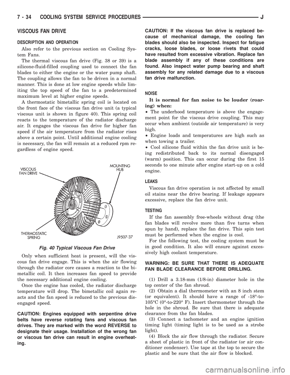
The thermal viscous fan drive (Fig. 38 or 39) is a
silicone-fluid-filled coupling used to connect the fan
blades to either the engine or the water pump shaft.
The coupling allows the fan to be driven in a normal
manner. This is done at low engine speeds while lim-
iting the top speed of the fan to a predetermined
maximum level at higher engine speeds.
A thermostatic bimetallic spring coil is located on
the front face of the viscous fan drive unit (a typical
viscous unit is shown in figure 40). This spring coil
reacts to the temperature of the radiator discharge
air. It engages the viscous fan drive for higher fan
speed if the air temperature from the radiator rises
above a certain point. Until additional engine cooling
is necessary, the fan will remain at a reduced rpm re-
gardless of engine speed.
Only when sufficient heat is present, will the vis-
cous fan drive engage. This is when the air flowing
through the radiator core causes a reaction to the bi-
metallic coil. It then increases fan speed to provide
the necessary additional engine cooling.
Once the engine has cooled, the radiator discharge
temperature will drop. The bimetallic coil again re-
acts and the fan speed is reduced to the previous dis-
engaged speed.
CAUTION: Engines equipped with serpentine drive
belts have reverse rotating fans and viscous fan
drives. They are marked with the word REVERSE to
designate their usage. Installation of the wrong fan
or viscous fan drive can result in engine overheat-
ing.CAUTION: If the viscous fan drive is replaced be-
cause of mechanical damage, the cooling fan
blades should also be inspected. Inspect for fatigue
cracks, loose blades, or loose rivets that could
have resulted from excessive vibration. Replace fan
blade assembly if any of these conditions are
found. Also inspect water pump bearing and shaft
assembly for any related damage due to a viscous
fan drive malfunction.
NOISE
It is normal for fan noise to be louder (roar-
ing) when:
²The underhood temperature is above the engage-
ment point for the viscous drive coupling. This may
occur when ambient (outside air temperature) is very
high.
²Engine loads and temperatures are high such as
when towing a trailer.
²Cool silicone fluid within the fan drive unit is be-
ing redistributed back to its normal disengaged
(warm) position. This can occur during the first 15
seconds to one minute after engine start-up on a cold
engine.
LEAKS
Viscous fan drive operation is not affected by small
oil stains near the drive bearing. If leakage appears
excessive, replace the fan drive unit.
TESTING
If the fan assembly free-wheels without drag (the
fan blades will revolve more than five turns when
spun by hand), replace the fan drive. This spin test
must be performed when the engine is cool.
For the following test, the cooling system must be
in good condition. It also will ensure against exces-
sively high coolant temperature.
WARNING: BE SURE THAT THERE IS ADEQUATE
FAN BLADE CLEARANCE BEFORE DRILLING.
(1) Drill a 3.18-mm (1/8-in) diameter hole in the
top center of the fan shroud.
(2) Obtain a dial thermometer with an 8 inch stem
(or equivalent). It should have a range of -18É-to-
105ÉC (0É-to-220É F). Insert thermometer through the
hole in the shroud. Be sure that there is adequate
clearance from the fan blades.
(3) Connect a tachometer and an engine ignition
timing light (timing light is to be used as a strobe
light).
(4) Block the air flow through the radiator. Secure
a sheet of plastic in front of the radiator (or air con-
ditioner condenser). Use tape at the top to secure the
plastic and be sure that the air flow is blocked.
Fig. 40 Typical Viscous Fan Drive
7 - 34 COOLING SYSTEM SERVICE PROCEDURESJ
Page 414 of 2198
TURN SIGNAL AND HAZARD WARNING SYSTEMS
CONTENTS
page page
DIAGNOSIS............................. 3
GENERAL INFORMATION.................. 1SERVICE PROCEDURES................... 5
GENERAL INFORMATION
Following are general descriptions of the major
components in the XJ (Cherokee)/YJ (Wrangler)
model turn signal and hazard warning systems. Refer
to Group 8W - Wiring Diagrams for complete circuit
descriptions and diagrams.
TURN SIGNAL SYSTEM
With the ignition switch in the ON or ACCESSORY
position and the turn signal switch lever (YJ) or
multi-function switch control lever (XJ) moved up
(right turn) or down (left turn), the turn signal sys-
tem is activated.
When the turn signal system is activated, the se-
lected (right or left) turn signal indicator lamp, front
park/turn signal lamp and rear tail/stop/turn signal
lamp bulb filaments will flash. With the headlamp
switch in the OFF position, the turn and front side
marker lamps flash in unison. With the headlamp
switch in the ON position, the turn and front side
marker lamps flash alternately.
HAZARD WARNING SYSTEM
The hazard warning is activated by a switch button
located below the ignition lock cylinder (YJ) or on the
top of the steering column (XJ) between the steering
wheel and the instrument panel. The hazard warning
flasher (YJ) or combination flasher (XJ) receives bat-
tery feed at all times, and the system is functional
regardless of ignition switch position. The hazard
warning switch button is identified with a double
triangle. On YJ models, push the switch button in to
activate the hazard warning system and pull the
button out to turn system off. On XJ models, push in
on the switch button to latch the switch and activate
the hazard warning system, and push in on the
switch button again to unlatch the switch and turn
the system off.
When the hazard warning system is activated, all
(right and left) turn signal indicator, front park/turn
signal lamp and rear tail/stop/turn signal lamp bulb
filaments will flash.
TURN SIGNAL FLASHER (YJ ONLY)
The turn signal flasher is located in the fuseblock
module. It contains one fixed contact point and one
contact point attached to a flexible bimetal arm. The
contact points are normally closed. When a turn sig-
nal is activated, current flows through the flasher. As
current flows through the bimetal arm it heats and
flexes to pull the contact points open, stopping cur-
rent flow. As the bimetal arm cools it straightens,
until the contact points close and the cycle repeats.
The standard flasher is designed to handle the cur-
rent flow requirements of the factory installed light-
ing. If supplemental lighting is added to the turn
signal circuits such as when towing a trailer with
lights, the current flow through the flasher increases.
This causes the flash rate to increase. It is recom-
mended that the standard flasher be replaced with a
heavy-duty (hazard warning) flasher when supple-
mental lighting is added.
However, when a turn signal bulb fails with a stan-
dard flasher, the remaining bulbs in that circuit will
light, but not flash. This will give the driver an indi-
cation to check the turn signal bulbs. Because a
heavy-duty flasher has different internal circuitry, a
failed bulb will not prevent the remaining bulbs in
the circuit from flashing. Therefore, it is recom-
mended that an occasional visual inspection of exte-
rior turn signal lamp operation be performed when a
heavy-duty flasher is installed.
HAZARD WARNING FLASHER (YJ ONLY)
The hazard warning flasher is located in the fuse-
block module. The hazard warning flasher contains
two normally open contact points mounted to two
flexible arms. A bimetal strip is attached between the
two arms. When the hazard warning is activated,
current flows through the flasher. As the current
flows through the bimetal strip it heats and pulls the
flexible arms together until the contact points close,
JTURN SIGNAL AND HAZARD WARNING SYSTEMS 8J - 1
Page 415 of 2198
allowing current flow to the lamps. As the bimetal
strip cools, the contact points are pushed open and
the cycle repeats.
COMBINATION FLASHER (XJ ONLY)
The combination flasher functions as both the turn
signal and hazard warning flasher on XJ models. The
combination flasher is a smart relay that is located in
the relay center under the lower instrument panel
and inboard of the steering column. The combination
flasher can not be repaired. If faulty, it must be
replaced.
The combination flasher is designed to handle the
current flow requirements of the factory installed
lighting. If supplemental lighting is added to the turn
signal circuits such as when towing a trailer with
lights, the combination flasher will automatically
compensate. This allows the flash rate to remain the
same, regardless of electrical load increases. However,
if a bulb fails in the turn signal or hazard warning
circuits, the flash rate of the remaining bulbs in that
circuit will increase to 120 flashes per minute or
higher.
TURN SIGNAL/HAZARD WARNING SWITCH
(YJ ONLY)
The turn signal and hazard warning switches are
combined into a single unit mounted within the upper
steering column bowl and beneath the steering wheel.
The turn signal lever on the left side of the steering
column is moved up or down to select the right or left
turn signal switch position. The turn signals will only
operate with the ignition switch in the ACCESSORY
or ON position.
The hazard warning button on the right side of the
steering column is pushed in to turn the hazard
warning system on, or pulled out to turn the system
off. The hazard warning system will operate regard-
less of ignition switch position. The turn signal/haz-
ard warning switch can not be repaired. If faulty, the
entire unit must be replaced.
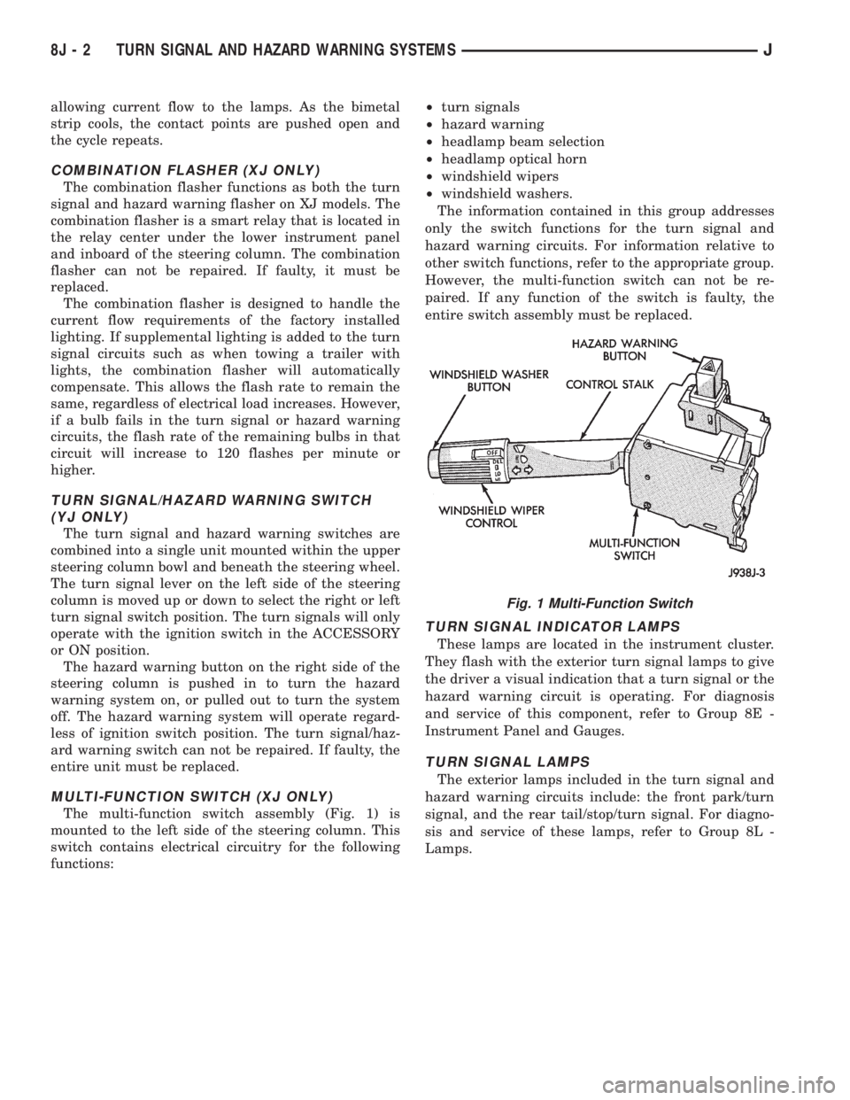
MULTI-FUNCTION SWITCH (XJ ONLY)
The multi-function switch assembly (Fig. 1) is
mounted to the left side of the steering column. This
switch contains electrical circuitry for the following
functions:²turn signals
²hazard warning
²headlamp beam selection
²headlamp optical horn
²windshield wipers
²windshield washers.
The information contained in this group addresses
only the switch functions for the turn signal and
hazard warning circuits. For information relative to
other switch functions, refer to the appropriate group.
However, the multi-function switch can not be re-
paired. If any function of the switch is faulty, the
entire switch assembly must be replaced.
TURN SIGNAL INDICATOR LAMPS
These lamps are located in the instrument cluster.
They flash with the exterior turn signal lamps to give
the driver a visual indication that a turn signal or the
hazard warning circuit is operating. For diagnosis
and service of this component, refer to Group 8E -
Instrument Panel and Gauges.
TURN SIGNAL LAMPS
The exterior lamps included in the turn signal and
hazard warning circuits include: the front park/turn
signal, and the rear tail/stop/turn signal. For diagno-
sis and service of these lamps, refer to Group 8L -
Lamps.
Fig. 1 Multi-Function Switch
8J - 2 TURN SIGNAL AND HAZARD WARNING SYSTEMSJ