1995 JEEP CHEROKEE fuel pressure
[x] Cancel search: fuel pressurePage 347 of 2198

HEADLAMP HIGH BEAM INDICATOR LAMP
The high beam indicator lamp is controlled by the
headlamp dimmer (multi-function) switch. One side
of the indicator bulb is grounded at all times. The
other side of the bulb receives battery feed through
the contacts of the dimmer switch when the multi-
function switch stalk is actuated to turn the head-
lamp high beams on. Refer to Group 8L - Lamps for
more information.
LOW FUEL WARNING LAMP
A Light-Emitting Diode (LED) on the face of the
fuel gauge will light when the fuel level falls below
approximately 4 gallons. A low fuel warning module
attached to the rear of the fuel gauge controls when
the LED will light. When the module senses 66.5
ohms or more resistance from the fuel level sending
unit for 10 continuous seconds, the LED will light.
When the module senses 63.5 ohms or less resistance
from the fuel level sending unit for 20 continuous
seconds, the LED is turned off.
LOW OIL PRESSURE WARNING LAMP
The low oil pressure warning lamp lights with the
ignition switch in the ON position and the engine not
running. The lamp should be off when the engine is
running. Battery voltage is supplied to one side of
the indicator bulb when the ignition switch is turned
ON. The warning lamp side of the combination oil
pressure sending unit is connected to the other side
of the bulb. When normal engine oil pressure is ap-
plied to the sending unit, resistance on the warning
lamp side is high and the lamp goes off. When engine
oil pressure is too low, resistance on the warning
lamp side of the sending unit is low, which causes
the bulb to light.
LOW WASHER FLUID WARNING LAMP
The low washer fluid warning lamp indicates when
the fluid level in the washer reservoir is too low. The
washer fluid level sensor uses a float in the reservoir
to monitor fluid level. The action of the float opens or
closes the switch within the sensor that provides ig-
nition-switched battery voltage to the lamp bulb. Re-
fer to Group 8K - Wiper and Washer Systems for
more information.
MALFUNCTION INDICATOR LAMP
The CHECK ENGINE or Malfunction Indicator
Lamp (MIL) lights each time the ignition switch is
turned ON, and stays on for 3 seconds as a bulb test.
If the Powertrain Control Module (PCM) receives an
incorrect signal or no signal from certain fuel oremission system related circuits or components, the
lamp is turned on. This will indicate that the PCM
has recorded a Diagnostic Trouble Code (DTC) in
electronic memory for a circuit or component mal-
function. Refer to Group 14 - Fuel System for more
information.
SEAT BELT REMINDER LAMP
The seat belt reminder lamp lights for 4 to 8 sec-
onds after the ignition switch is turned to the ON po-
sition. A timer in the chime/buzzer module controls
ignition-switched battery feed to the lamp. Refer to
Group 8U - Chime/Buzzer Warning Systems for more
information.
TURN SIGNAL INDICATOR LAMPS
The left and right turn signal indicator lamps are
controlled by the turn signal and hazard warning
(multi-function) switches. One side of the bulb for
each lamp is grounded at all times. The other side of
the bulb receives battery feed through the contacts of
the multi-function switch when the turn signal lever
(multi-function switch stalk) or hazard warning but-
ton are actuated. Refer to Group 8J - Turn Signal
and Hazard Warning Systems for more information.
UPSHIFT INDICATOR LAMP
Vehicles equipped with manual transmissions have
an optional upshift indicator lamp. Ground feed for
the lamp is switched by the Powertrain Control Mod-
ule (PCM). The lamp lights to indicate when the
driver should shift to the next highest gear for best
fuel economy. The PCM will turn the lamp off after 3
to 5 seconds if the upshift is not performed. The lamp
will remain off until the vehicle stops accelerating
and is brought back to the range of lamp operation,
or until the transmission is shifted into another gear.
The indicator lamp is normally on when the igni-
tion switch is turned ON and is turned off when the
engine is started. The lamp will be turned on during
vehicle operation according to engine speed and load.
CLUSTER ILLUMINATION LAMPS
All cluster illumination lamps receive battery feed
from the instrument lamps fuse in the fuseblock
module through the panel dimmer rheostat of the
headlamp switch. When the park or headlamps are
on, the cluster illumination lamps light. Illumination
brightness can be adjusted by rotating the headlamp
switch knob (clockwise to dim, counterclockwise to
brighten).
8E - 4 INSTRUMENT PANEL AND GAUGESÐXJJ
Page 349 of 2198
(5) Probe cavity B1 of cluster connector A. Check
for continuity to a good ground. There should be no
continuity. If OK, go to next step. If not OK, repair
short circuit as required.
(6) Still probing cavity B1 of cluster connector A,
check for continuity to cavity B of sending unit body
half connector. There should be continuity. If OK, re-
place gauge. If not OK, repair open circuit as re-
quired.
OIL PRESSURE GAUGE
The diagnosis found here addresses an inoperative
gauge condition. If the problem being diagnosed is re-
lated to gauge accuracy, be certain to confirm that
problem is with gauge and not with engine oiling sys-
tem performance. Actual engine oil pressure should
be checked with a test gauge and compared to gauge
readings before you proceed with gauge diagnosis.
Refer to Group 9 - Engines for more information.
(1) Turn ignition switch to ON. Disconnect oil pres-
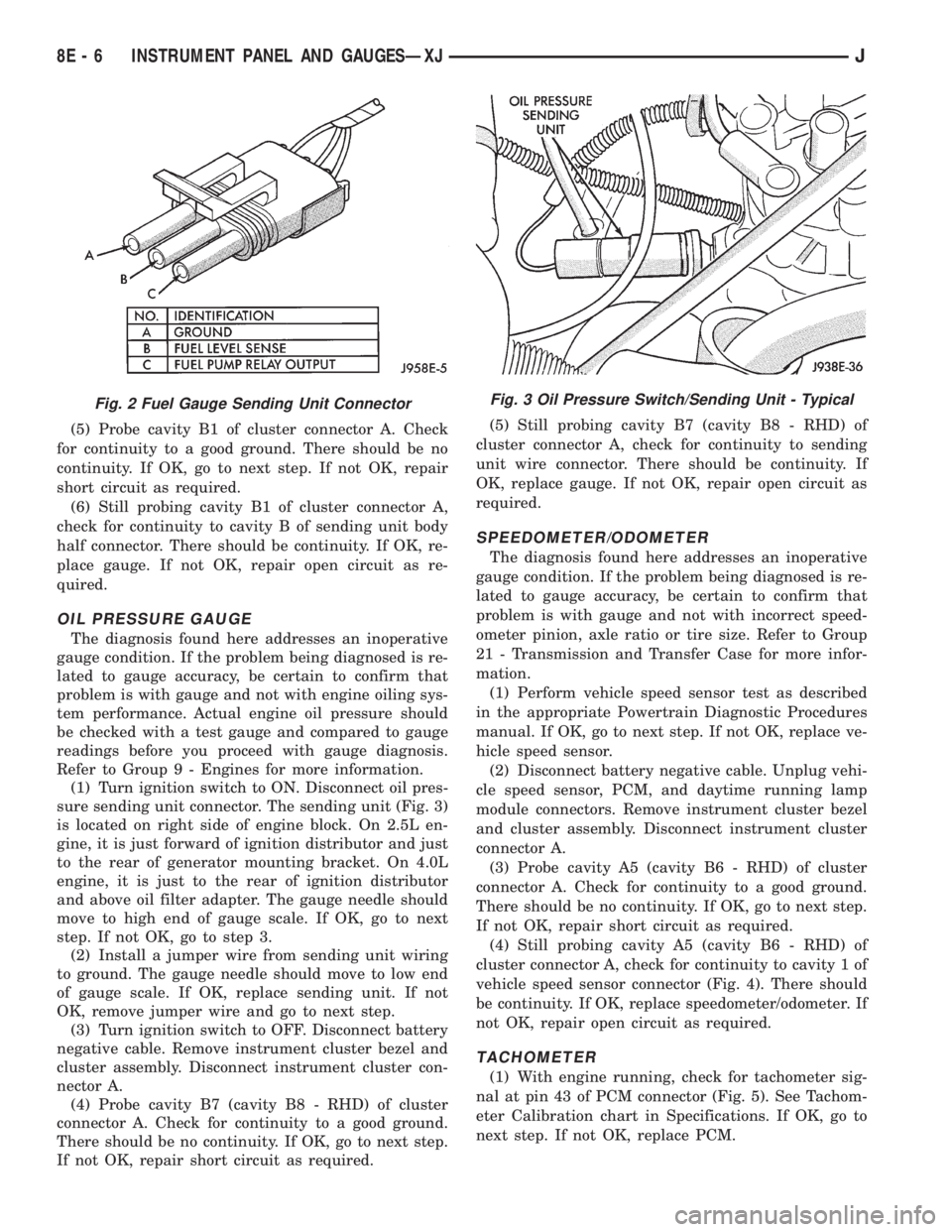
sure sending unit connector. The sending unit (Fig. 3)
is located on right side of engine block. On 2.5L en-
gine, it is just forward of ignition distributor and just
to the rear of generator mounting bracket. On 4.0L
engine, it is just to the rear of ignition distributor
and above oil filter adapter. The gauge needle should
move to high end of gauge scale. If OK, go to next
step. If not OK, go to step 3.
(2) Install a jumper wire from sending unit wiring
to ground. The gauge needle should move to low end
of gauge scale. If OK, replace sending unit. If not
OK, remove jumper wire and go to next step.
(3) Turn ignition switch to OFF. Disconnect battery
negative cable. Remove instrument cluster bezel and
cluster assembly. Disconnect instrument cluster con-
nector A.
(4) Probe cavity B7 (cavity B8 - RHD) of cluster
connector A. Check for continuity to a good ground.
There should be no continuity. If OK, go to next step.
If not OK, repair short circuit as required.(5) Still probing cavity B7 (cavity B8 - RHD) of
cluster connector A, check for continuity to sending
unit wire connector. There should be continuity. If
OK, replace gauge. If not OK, repair open circuit as
required.
SPEEDOMETER/ODOMETER
The diagnosis found here addresses an inoperative
gauge condition. If the problem being diagnosed is re-
lated to gauge accuracy, be certain to confirm that
problem is with gauge and not with incorrect speed-
ometer pinion, axle ratio or tire size. Refer to Group
21 - Transmission and Transfer Case for more infor-
mation.
(1) Perform vehicle speed sensor test as described
in the appropriate Powertrain Diagnostic Procedures
manual. If OK, go to next step. If not OK, replace ve-
hicle speed sensor.
(2) Disconnect battery negative cable. Unplug vehi-
cle speed sensor, PCM, and daytime running lamp
module connectors. Remove instrument cluster bezel
and cluster assembly. Disconnect instrument cluster
connector A.
(3) Probe cavity A5 (cavity B6 - RHD) of cluster
connector A. Check for continuity to a good ground.
There should be no continuity. If OK, go to next step.
If not OK, repair short circuit as required.
(4) Still probing cavity A5 (cavity B6 - RHD) of
cluster connector A, check for continuity to cavity 1 of
vehicle speed sensor connector (Fig. 4). There should
be continuity. If OK, replace speedometer/odometer. If
not OK, repair open circuit as required.
TACHOMETER
(1) With engine running, check for tachometer sig-
nal at pin 43 of PCM connector (Fig. 5). See Tachom-
eter Calibration chart in Specifications. If OK, go to
next step. If not OK, replace PCM.
Fig. 2 Fuel Gauge Sending Unit ConnectorFig. 3 Oil Pressure Switch/Sending Unit - Typical
8E - 6 INSTRUMENT PANEL AND GAUGESÐXJJ
Page 357 of 2198
(2) Disconnect battery negative cable. Remove in-
strument cluster bezel and cluster assembly. Unplug
cluster connector A. Connect battery negative cable.
Turn headlamps on and select high beam. Check for
battery voltage at cavity A4 of cluster connector A. If
OK, replace indicator bulb. If not OK, repair circuit
to headlamp dimmer (multi-function) switch as re-
quired.
LOW FUEL WARNING LAMP
(1) Check that fuel gauge is operating as designed.
See Fuel Gauge Calibration chart in Specifications. If
OK, go to next step. If not OK, see Fuel Gauge in
this section for diagnosis.
(2) With at least 10 gallons of fuel in fuel tank, un-
plug fuel tank sending unit connector. Turn ignition
switch to ON and wait 10 seconds. Lamp (LED)
should light. Reconnect fuel tank sending unit and
wait 20 seconds. Lamp (LED) should go off. If not
OK, replace low fuel warning lamp module.
LOW OIL PRESSURE WARNING LAMP
The diagnosis found here addresses an inoperative
lamp condition. If the problem being diagnosed is re-
lated to lamp accuracy, be certain to confirm that
problem is with lamp and not with engine oiling sys-
tem. Actual engine oil pressure should be checked
with a test gauge before you proceed with lamp diag-
nosis. Refer to Group 9 - Engines for more informa-
tion.
(1) Turn ignition switch to ON. Lamp should light.
Start engine. Lamp should go off. If not OK, turn en-
gine off and go to next step.
(2) Unplug connector at oil pressure switch (Fig.
3). The switch is located on right side of engine block.
On 2.5L engine, it is just forward of ignition distrib-
utor and just to the rear of generator mounting
bracket. On 4.0L engine, it is just to the rear of igni-
tion distributor and above oil filter adapter. Install a
jumper wire from connector to a good ground. Turn
ignition switch to ON. Lamp should light. Unplug
jumper wire. Lamp should go out. If OK, replace oil
pressure switch. If not OK, go to next step.
(3) Turn ignition switch to OFF. Disconnect battery
negative cable. Remove instrument cluster bezel and
cluster assembly. Install a jumper wire from cavity
B7 (cavity B8 - RHD) of cluster connector A to a good
ground. Connect battery negative cable and turn ig-
nition switch to ON. Lamp should light. If OK, go to
next step. If not OK, replace lamp bulb.
(4) Turn ignition switch to OFF. Disconnect battery
negative cable. Unplug instrument cluster connector
A. Check continuity between cavity B7 (cavity B8 -
RHD) of cluster connector A and a good ground.
There should be no continuity. If OK, go to next step.
If not OK, repair short circuit as required.
(5) Check continuity between cavity B7 (cavity B8
- RHD) of cluster connector A and oil pressure switchconnector. There should be continuity. If not OK, re-
pair open circuit as required.
LOW WASHER FLUID WARNING LAMP
(1) Unplug washer fluid level switch connector.
Turn ignition switch to ON. Check for battery voltage
at connector cavity A. If OK, turn ignition switch to
OFF and go to next step. If not OK, repair open cir-
cuit to fuse F6 in PDC.
(2) Install a jumper wire from cavity A to cavity B
of washer fluid level switch connector. Turn ignition
switch to ON. Lamp should light. Unplug jumper and
lamp should go OFF. If OK, replace washer fluid
level switch. If not OK, go to next step.
(3) Turn ignition switch to OFF. Disconnect battery
negative cable. Remove instrument cluster bezel and
cluster assembly. Unplug instrument cluster (tell-
tale) connector B. Check continuity between cavity 16
(cavity 1 - RHD) of cluster connector B and a good
ground. There should be continuity. If OK, plug clus-
ter connector B back into cluster and go to next step.
If not OK, repair open circuit to ground as required.
(4) Connect battery negative cable. Install a
jumper wire from a 12-volt battery feed to cavity 1
(cavity 16 - RHD) of cluster connector B. Lamp
should light. If OK, go to next step. If not OK, re-
place bulb.
(5) Disconnect battery negative cable. Unplug clus-
ter connector B. Check continuity between cavity 1
(cavity 16 - RHD) of cluster connector B and a good
ground. There should be no continuity. If OK, go to
next step. If not OK, repair short circuit to switch as
required.
(6) Check continuity between cavity 1 (cavity 16 -
RHD) of cluster connector B and cavity B of washer
fluid level switch connector. There should be continu-
ity. If not OK, repair open circuit to switch as re-
quired.
MALFUNCTION INDICATOR LAMP
The diagnosis found here addresses an inoperative
lamp condition. If the lamp comes on and stays on
with engine running, refer to Group 14 - Fuel System
for diagnosis. If no fuel or emission system problem
is found, the following procedure will help locate a
short or open in the lamp circuit.
(1) Disconnect battery negative cable. Unplug PCM
connector. Install a jumper wire from cavity 32 of
PCM connector (Fig. 5) to a good ground. Connect
battery negative cable. Turn ignition switch to ON.
Lamp should light. Remove jumper wire and lamp
should go OFF. If OK, refer to Powertrain Diagnostic
Procedures to check PCM. If not OK, go to next step.
(2) Turn ignition switch to OFF. Disconnect battery
negative cable. Remove instrument cluster bezel and
cluster assembly. Install a jumper wire from cavity 2
(cavity 15 - RHD) of cluster (tell-tale) connector B to
a good ground. Connect battery negative cable. Turn
8E - 14 INSTRUMENT PANEL AND GAUGESÐXJJ
Page 367 of 2198
INSTRUMENT PANEL AND GAUGESÐYJ
CONTENTS
page page
INSTRUMENT PANEL AND GAUGESÐYJ..... 22
DIAGNOSIS............................ 23
GENERAL INFORMATION................. 20SERVICE PROCEDURES.................. 31
SPECIFICATIONS........................ 39
GENERAL INFORMATION
Following are general descriptions of major instru-
ment panel components. Refer to Group 8W - Wiring
Diagrams for complete circuit descriptions and dia-
grams.
INSTRUMENT PANEL
Modular instrument panel construction allows all
gauges and controls to be serviced from the front of
the panel. In addition, most instrument panel wiring
and heater components can be accessed without com-
plete instrument panel removal.
Removal of the left instrument cluster bezel allows
access to the main cluster assembly and most
switches. Removal of the center cluster bezel allows
access to the gauge package cluster assembly, the
heater controls, and the radio. Removal of the cluster
assemblies allows access to the individual gauges, il-
lumination and indicator lamp bulbs, printed cir-
cuits, and most wiring.
INSTRUMENT CLUSTERS
The instrument cluster used on YJ (Wrangler) mod-
els consists of two separate assemblies. The main
cluster assembly is located on the left side of the in-
strument panel, centered over the steering column
opening. The gauge package cluster assembly is lo-
cated near the center of the instrument panel. Each
cluster assembly is served by a separate printed cir-
cuit and wiring connector. Some variations of each
cluster exist due to optional equipment and regula-
tory requirements.
The main cluster assembly includes a speedometer/
odometer/trip odometer and a tachometer. It also in-
cludes provisions for the following indicator lamps:
²anti-lock brake system lamp
²brake warning lamp
²headlamp high beam indicator lamp
²malfunction indicator (Check Engine) lamp
²seat belt reminder lamp²turn signal indicator lamps
²upshift indicator lamp.
The gauge package cluster assembly includes a
four-wheel drive indicator lamp and the following
gauges:
²coolant temperature gauge
²fuel gauge
²oil pressure gauge
²voltmeter.
GAUGES
With the ignition switch in the ON or START posi-
tion, voltage is supplied to all gauges through the
two cluster printed circuits. With the ignition switch
in the OFF position, voltage is not supplied to the
gauges. A gauge pointer may remain within the
gauge scale after the ignition switch is OFF. How-
ever, the gauges do not accurately indicate any vehi-
cle condition unless the ignition switch is ON.
All gauges except the odometer are air core mag-
netic units. Two fixed electromagnetic coils are lo-
cated within the gauge. These coils are wrapped at
right angles to each other around a movable perma-
nent magnet. The movable magnet is suspended
within the coils on one end of a shaft. The gauge nee-
dle is attached to the other end of the shaft.
One of the coils has a fixed current flowing through
it to maintain a constant magnetic field strength.
Current flow through the second coil changes, which
causes changes in its magnetic field strength. The
current flowing through the second coil can be
changed by:
²a variable resistor-type sending unit (fuel level,
coolant temperature, or oil pressure)
²changes in electrical system voltage (voltmeter)
²electronic control circuitry (speedometer/odometer,
tachometer).
8E - 24 INSTRUMENT PANEL AND GAUGESÐYJJ
Page 368 of 2198
The gauge needle moves as the movable permanent
magnet aligns itself to the changing magnetic fields
created around it by the electromagnets.
COOLANT TEMPERATURE GAUGE
The coolant temperature gauge gives an indication
of engine coolant temperature. The coolant tempera-
ture sending unit is a thermistor that changes elec-
trical resistance with changes in engine coolant
temperature. High sending unit resistance causes
low coolant temperature readings. Low resistance
causes high coolant temperature readings. Sending
unit resistance values are shown in a chart in Spec-
ifications.
FUEL GAUGE
The fuel gauge gives an indication of the level of
fuel in the fuel tank. The fuel gauge sending unit has
a float attached to a swing-arm in the fuel tank. The
float moves up or down within the fuel tank as fuel
level changes. As the float moves, an electrical con-
tact on the swing-arm wipes across a resistor coil,
which changes sending unit resistance. High sending
unit resistance causes high fuel level readings. Low
resistance causes low fuel level readings. Sending
unit resistance values are shown in a chart in Spec-
ifications.
OIL PRESSURE GAUGE
The oil pressure gauge gives an indication of en-
gine oil pressure. The combination oil pressure send-
ing unit contains a flexible diaphragm. The
diaphragm moves in response to changes in engine
oil pressure. As the diaphragm moves, sending unit
resistance increases or decreases. High resistance on
the gauge side of the sending unit causes high oil
pressure readings. Low resistance causes low oil
pressure readings. Sending unit resistance values are
shown in a chart in Specifications.
SPEEDOMETER/ODOMETER
The speedometer/odometer give an indication of ve-
hicle speed and travel distance. The speedometer re-
ceives a vehicle speed pulse signal from the Vehicle
Speed Sensor (VSS). An electronic integrated circuit
contained within the speedometer reads and analyzes
the pulse signal. It then adjusts the ground path re-
sistance of one electromagnet in the gauge to control
needle movement. It also sends signals to an electric
stepper motor to control movement of the odometer
number rolls. Frequency values for the pulse signal
are shown in a chart in Specifications.
The VSS is mounted to an adapter near the trans-
fer case output shaft. The sensor is driven through
the adapter by a speedometer pinion gear. The
adapter and pinion vary with transmission, axle ratio
and tire size. Refer to Group 21 - Transmission and
Transfer Case for more information.
TACHOMETER
The tachometer gives an indication of engine speed
in Revolutions-Per-Minute (RPM). With the engine
running, the tachometer receives an engine speed
pulse signal from the Powertrain Control Module
(PCM). An electronic integrated circuit contained
within the tachometer reads and analyzes the pulse
signal. It then adjusts the ground path resistance of
one electromagnet in the gauge to control needle
movement. Frequency values for the pulse signal are
shown in a chart in Specifications.
TRIP ODOMETER
The trip odometer is driven by the same electronic
integrated circuit as the speedometer/odometer. How-
ever, by depressing the trip odometer reset knob on
the face of the speedometer, the trip odometer can be
reset to zero. The trip odometer is serviced only as a
part of the speedometer/odometer gauge assembly.
VOLTMETER
The voltmeter is connected in parallel with the bat-
tery. With the ignition switch ON, the voltmeter in-
dicates battery or generator output voltage,
whichever is greater.
INDICATOR LAMPS
All indicator lamps, except the four-wheel drive in-
dicator, are located in the main cluster tell-tale area
above the steering column opening. Each of the
lamps is served by the main cluster printed circuit
and cluster connector. The four-wheel drive indicator
lamp is located in the gauge package cluster and is
served by the gauge package printed circuit and clus-
ter connector.
Up to eleven indicator lamps can be found in the
tell-tale area of the main cluster. These lamps are ar-
ranged in two rows, with six lamps in the upper row
and five lamps in the lower row.
ANTI-LOCK BRAKE SYSTEM LAMP
The Anti-Lock Brake System (ABS) lamp is
switched to ground by the ABS module. The module
lights the lamp when the ignition switch is turned to
the START position as a bulb test. The lamp will
stay on for 3 to 5 seconds after vehicle start-up to in-
dicate a system self-test is in process. If the lamp re-
mains on after start-up, or comes on and stays on
while driving, it may indicate that the ABS module
has detected a system malfunction or that the system
has become inoperative. Refer to Group 5 - Brakes
for more information.
BRAKE WARNING LAMP
The brake warning lamp warns the driver that the
parking brake is applied or that the pressures in the
two halves of the split brake hydraulic system are
unequal. With the ignition switch turned ON, battery
JINSTRUMENT PANEL AND GAUGESÐYJ 8E - 25
Page 369 of 2198
voltage is supplied to one side of the indicator bulb. A
ground path for the bulb is provided by 3 switches.
The bulb will light when:
²the brake warning switch is closed (indicating un-
equal brake system hydraulic pressures possibly due
to brake fluid leakage)
²the ignition switch is in the START position (bulb
test)
²the parking brake switch is closed (parking brake
is applied).
Refer to Group 5 - Brakes for more information.
FOUR-WHEEL DRIVE INDICATOR LAMP
This lamp lights when the transfer case is engaged
in the 4H or 4L position. Voltage is supplied to one
side of the indicator bulb. A switch on the front axle
disconnect housing is connected to the other side of
the indicator bulb. When the switch is closed, a path
to ground is provided and the indicator bulb lights.
HEADLAMP HIGH BEAM INDICATOR LAMP
The high beam indicator lamp is controlled by the
headlamp dimmer switch. One side of the indicator
bulb is grounded at all times. The other side of the
bulb receives battery feed through the contacts of the
dimmer switch when the turn signal switch lever is
actuated to turn the headlamp high beams on. Refer
to Group 8L - Lamps for more information.
MALFUNCTION INDICATOR LAMP
The CHECK ENGINE or Malfunction Indicator
Lamp (MIL) lights each time the ignition switch is
turned ON, and stays on for 3 seconds as a bulb test.
If the Powertrain Control Module (PCM) receives an
incorrect signal or no signal from certain fuel or
emission system related circuits or components, the
lamp is turned on. This will indicate that the PCM
has recorded a Diagnostic Trouble Code (DTC) in
electronic memory for a circuit or component mal-
function. Refer to Group 14 - Fuel System for more
information.
SEAT BELT REMINDER LAMP
The seat belt reminder lamp lights for 4 to 8 sec-
onds after the ignition switch is turned to the ON po-sition. A timer in the chime/buzzer module controls
ignition-switched battery feed to the lamp. Refer to
Group 8U - Chime/Buzzer Warning Systems for more
information.
TURN SIGNAL INDICATOR LAMPS
The left and right turn signal indicator lamps are
controlled by the turn signal and hazard warning
switches. One side of the bulb for each lamp is
grounded at all times. The other side of the bulb re-
ceives battery feed through the contacts of the turn
signal switch, when the turn signal lever or hazard
warning button are actuated. Refer to Group 8J -
Turn Signal and Hazard Warning Systems for more
information.
UPSHIFT INDICATOR LAMP
Vehicles equipped with manual transmissions have
an optional upshift indicator lamp. Ground feed for
the lamp is switched by the Powertrain Control Mod-
ule (PCM). The lamp lights to indicate when the
driver should shift to the next highest gear for best
fuel economy. The PCM will turn the lamp off after 3
to 5 seconds if the upshift is not performed. The lamp
will remain off until the vehicle stops accelerating
and is brought back to the range of lamp operation,
or until the transmission is shifted into another gear.
The indicator lamp is normally on when the igni-
tion switch is turned ON and is turned off when the
engine is started. The lamp will be turned on during
vehicle operation according to engine speed and load.
CLUSTER ILLUMINATION LAMPS
All cluster illumination lamps receive battery feed
from the instrument lamps fuse in the fuseblock
module through the panel dimmer switch. When the
park or headlamps are on, the cluster illumination
lamps light. Illumination brightness can be adjusted
by rotating the panel dimmer thumb-wheel, which is
next to the headlamp switch.
8E - 26 INSTRUMENT PANEL AND GAUGESÐYJJ
Page 371 of 2198
continuity. If OK, go to next step. If not OK, repair
circuit to ground as required.
(4) Remove center instrument cluster bezel and
gauge package cluster assembly. Disconnect cluster
connector.
(5) Probe cavity 6 of cluster connector. Check for
continuity to a good ground. There should be no con-
tinuity. If OK, go to next step. If not OK, repair short
circuit as required.
(6) Still probing cavity 6 of cluster connector, check
for continuity to cavity 2 of sending unit wiring body
half connector. There should be continuity. If OK, re-
place gauge. If not OK, repair open circuit as re-
quired.
OIL PRESSURE GAUGE
The diagnosis found here addresses an inoperative
gauge condition. If the problem being diagnosed is re-
lated to gauge accuracy, be certain to confirm that
problem is with gauge and not with engine oiling sys-
tem performance. Actual engine oil pressure should
be checked with a test gauge and compared to gauge
readings before you proceed with gauge diagnosis.
Refer to Group 9 - Engines for more information.
(1) Turn ignition switch to ON. Disconnect oil pres-
sure sending unit connector. The sending unit (Fig. 3)
is located on right side of engine block. On 2.5L en-
gine, it is just forward of ignition distributor and just
to the rear of generator mounting bracket. On 4.0L
engine, it is just to the rear of ignition distributor
and above oil filter adapter. The gauge needle should
move to high end of gauge scale. If OK, go to next
step. If not OK, go to step 3.
(2) Install a jumper wire from sending unit wiring
to ground. The gauge needle should move to low end
of gauge scale. If OK, replace sending unit. If not
OK, remove jumper wire and go to next step.(3) Turn ignition switch to OFF. Disconnect battery
negative cable. Remove center instrument cluster be-
zel and gauge package cluster assembly. Disconnect
cluster connector.
(4) Probe cavity 9 of cluster connector. Check for
continuity to a good ground. There should be no con-
tinuity. If OK, go to next step. If not OK, repair short
circuit as required.
(5) Still probing cavity 9 of cluster connector, check
for continuity to sending unit wire connector. There
should be continuity. If OK, replace gauge. If not OK,
repair open circuit as required.
SPEEDOMETER/ODOMETER
The diagnosis found here addresses an inoperative
gauge condition. If the problem being diagnosed is re-
lated to gauge accuracy, be certain to confirm that
problem is with gauge and not with incorrect speed-
ometer pinion, axle ratio or tire size. Refer to Group
21 - Transmission and Transfer Case for more infor-
mation.
(1) Perform vehicle speed sensor test as described
in the appropriate Powertrain Diagnostic Procedures
manual. If OK, go to next step. If not OK, replace ve-
hicle speed sensor.
(2) Disconnect battery negative cable. Unplug vehi-
cle speed sensor, PCM, and daytime running lamp
module connectors. Remove left instrument cluster
bezel and main cluster assembly. Disconnect cluster
connector.
(3) Probe cavity 13 of cluster connector. Check for
continuity to a good ground. There should be no con-
tinuity. If OK, go to next step. If not OK, repair short
circuit as required.
(4) Still probing cavity 13 of cluster connector,
check for continuity to cavity 1 of vehicle speed sen-
sor connector (Fig. 4). There should be continuity. If
OK, replace speedometer/odometer. If not OK, repair
open circuit as required.
Fig. 2 Fuel Gauge Sending Unit ConnectorFig. 3 Oil Pressure Sending Unit - Typical
8E - 28 INSTRUMENT PANEL AND GAUGESÐYJJ
Page 576 of 2198
FUEL/IGNITION
INDEX
page page
Automatic Shut Down (ASD) Relay............. 1
Battery Feed.............................. 1
Brake Switch Input......................... 5
Camshaft Position Sensor.................... 3
CCDBus ................................ 5
Crankshaft Position Sensor................... 3
Data Link Connector........................ 5
Diagram Index Ð2.5L Engine.................. 6
Diagram Index Ð4.0L Engine.................. 6
Engine Coolant Temperature Sensor............ 3
Extended Idle Switch....................... 5
Fuel Injectors............................. 1
Fuel Pump Module......................... 2
Fuel Pump Relay.......................... 2
Heated Oxygen Sensor...................... 3Idle Air Control (IAC) Motor................... 2
Ignition Coil.............................. 2
Ignition Switch............................ 1
Intake Air Temperature Sensor................ 4
Malfunction Indicator Lamp (MIL)............... 5
Manifold Absolute Pressure Sensor............. 4
Park/Neutral Position Switch.................. 4
Power (Device) Ground...................... 5
Power Steering Pressure Switch............... 5
Tachometer Signal......................... 5
Throttle Position Sensor..................... 4
Torque Converter Clutch (TCC) Solenoid and
Relay................................. 4
Upshift Lamp............................. 5
Vehicle Speed Sensor....................... 2
IGNITION SWITCH
Circuit A1 from fuse 11 in the power distribution
center (PDC), supplies battery voltage to the ignition
switch. Depending upon position, the ignition switch
powers circuits A21, A38, A41, or A48.
START POSITION
In the START position, the ignition switch connects
circuit A1 to circuit A41. Circuit A41 connects to the
coil side of the starter motor relay.
Additionally in the START position, the case
grounded ignition switch provides ground for the
brake lamp switch and the warning lamps in the
instrument cluster.
START OR RUN POSITION
In the START or RUN position, the ignition switch
connects circuit A1 to circuit A21. Circuit A21 splices
to power fuse 17 in the fuse block and the coil side of
the Automatic Shut Down (ASD) relay and the fuel
pump relay.
RUN (ONLY) POSITION
When the ignition switch is in the RUN position, it
connects circuit A1 to circuit A38. Circuit A22 splices
to power fuses 1 and 7 in the fuse block.
²Fuse 1 powers the rear wiper system on circuit
V15.
²Fuse 7 feeds the Anti-Lock Brake System (ABS) on
circuit 236.
ACCESSORY OR RUN POSITIONS
In the ACCESSORY or RUN positions, the ignition
switch connects circuit A1 to circuit A48. Circuit A48
connects to a bus bar in the fuse block that feeds
fuses 2, 5, and 8.
AUTOMATIC SHUT DOWN (ASD) RELAY
When the ignition switch is in either the START or
RUN positions, it connects circuit A1 from fuse 6 in
the Power Distribution Center (PDC) to circuit A21.
Circuit A21 supplies battery voltage to the coil side of
the Automatic Shut Down (ASD) relay. The Power-
train Control Module (PCM) provides ground for the
relay on circuit K51. Circuit K51 connects to cavity 51
of the PCM.
When the PCM grounds the ASD relay, contacts
inside the relay close and connect circuit A18 from
fuse 14 in the PDC to circuit A142. Circuit A142
splices to the generator field terminal, fuel injectors,
and ignition coil. Circuit A142 also connects to cavity
57 of the PCM.
HELPFUL INFORMATION
²Along with supplying voltage to the coil side of the
ASD relay, circuit A21 also supplies voltage to the coil
side of the fuel pump relay.
BATTERY FEED
Circuit A14 from fuse 2 in the Power Distribution
Center (PDC) supplies battery voltage to cavity 3 of
the powertrain control module.
HELPFUL INFORMATION
Circuit A14 also supplies power to the contact sides
of the fuel pump relay and fuse F2 in the PDC. Fuse
F2 powers circuit A18 which supplies voltage to the
contact side of the automatic shut down relay.
FUEL INJECTORS
When the Automatic Shut Down (ASD) relay con-
tacts close, they connect circuits A14 and A142. Cir-
J8W-30 FUEL/IGNITIONÐXJ VEHICLES 8W - 30 - 1