1995 JEEP CHEROKEE clock
[x] Cancel search: clockPage 331 of 2198
REMOVALÐ2.5L OR 4.0L ENGINE
(1) Disconnect the negative battery cable at the
battery.
(2) Disconnect coil secondary cable at coil.
(3) Remove distributor cap from distributor (2
screws). Do not remove cables from cap. Do not re-
move rotor.
(4) Disconnect the distributor wiring harness from
the main engine harness.
(5) Remove the cylinder number 1 spark plug.
(6) Hold a finger over the open spark plug hole.
Rotate the engine at the vibration dampener bolt un-
til compression (pressure) is felt.
Slowly continue to rotate the engine. Do this until
the timing index mark on the vibration damper pul-
ley aligns with the top dead center (TDC) mark (0
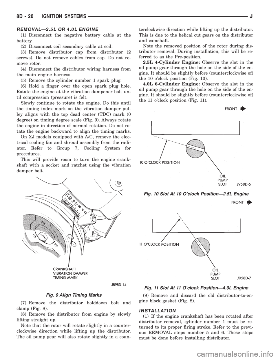
degree) on timing degree scale (Fig. 9). Always rotate
the engine in direction of normal rotation. Do not ro-
tate the engine backward to align the timing marks.
On XJ models equipped with A/C, remove the elec-
trical cooling fan and shroud assembly from the radi-
ator. Refer to Group 7, Cooling System for
procedures.
This will provide room to turn the engine crank-
shaft with a socket and ratchet using the vibration
damper bolt.
(7) Remove the distributor holddown bolt and
clamp (Fig. 8).
(8) Remove the distributor from engine by slowly
lifting straight up.
Note that the rotor will rotate slightly in a counter-
clockwise direction while lifting up the distributor.
The oil pump gear will also rotate slightly in a coun-terclockwise direction while lifting up the distributor.
This is due to the helical cut gears on the distributor
and camshaft.
Note the removed position of the rotor during dis-
tributor removal. During installation, this will be re-
ferred to as the Pre-position.
2.5L 4-Cylinder Engine:Observe the slot in the
oil pump gear through the hole on the side of the en-
gine. It should be slightly before (counterclockwise of)
the 10 o'clock position (Fig. 10).
4.0L 6-Cylinder Engine:Observe the slot in the
oil pump gear through the hole on the side of the en-
gine. It should be slightly before (counterclockwise of)
the 11 o'clock position (Fig. 11).
(9) Remove and discard the old distributor-to-en-
gine block gasket (Fig. 8).
INSTALLATION
(1) If the engine crankshaft has been rotated after
distributor removal, cylinder number 1 must be re-
turned to its proper firing stroke. Refer to the previ-
ous REMOVAL steps number 5 and 6. These steps
must be done before installing distributor.
Fig. 9 Align Timing Marks
Fig. 10 Slot At 10 O'clock PositionÐ2.5L Engine
Fig. 11 Slot At 11 O'clock PositionÐ4.0L Engine
8D - 20 IGNITION SYSTEMSJ
Page 332 of 2198
(2) Check the position of the slot on the oil pump
gear. On the 2.5L engine, it should be just slightly
before (counterclockwise of) the 10 o'clock position
(Fig. 10). On the 4.0L engine, it should be just
slightly before (counterclockwise of) the 11 o'clock po-
sition (Fig. 11). If not, place a flat blade screwdriver
into the oil pump gear and rotate it into the proper
position.
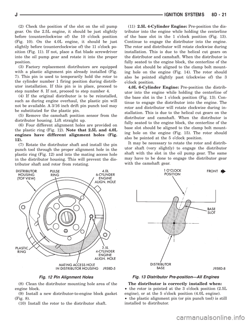
(3) Factory replacement distributors are equipped
with a plastic alignment pin already installed (Fig.
7). This pin is used to temporarily hold the rotor to
the cylinder number 1 firing position during distrib-
utor installation. If this pin is in place, proceed to
step number 8. If not, proceed to step number 4.
(4) If the original distributor is to be reinstalled,
such as during engine overhaul, the plastic pin will
not be available. A 3/16 inch drift pin punch tool may
be substituted for the plastic pin.
(5) Remove the camshaft position sensor from the
distributor housing. Lift straight up.
(6) Four different alignment holes are provided on
the plastic ring (Fig. 12).Note that 2.5L and 4.0L
engines have different alignment holes (Fig.
12).
(7) Rotate the distributor shaft and install the pin
punch tool through the proper alignment hole in the
plastic ring (Fig. 12) and into the mating access hole
in the distributor housing. This will prevent the dis-
tributor shaft and rotor from rotating.
(8) Clean the distributor mounting hole area of the
engine block.
(9) Install a new distributor-to-engine block gasket
(Fig. 8).
(10) Install the rotor to the distributor shaft.(11)2.5L 4-Cylinder Engine:Pre-position the dis-
tributor into the engine while holding the centerline
of the base slot in the 1 o'clock position (Fig. 13).
Continue to engage the distributor into the engine.
The rotor and distributor will rotate clockwise during
installation. This is due to the helical cut gears on
the distributor and camshaft. When the distributor is
fully seated to the engine block, the centerline of the
base slot should be aligned to the clamp bolt mount-
ing hole on the engine (Fig. 14). The rotor should
also be pointed slightly past (clockwise of) the 3
o'clock position.
4.0L 6-Cylinder Engine:Pre-position the distrib-
utor into the engine while holding the centerline of
the base slot in the 1 o'clock position (Fig. 13). Con-
tinue to engage the distributor into the engine. The
rotor and distributor will rotate clockwise during in-
stallation. This is due to the helical cut gears on the
distributor and camshaft. When the distributor is
fully seated to the engine block, the centerline of the
base slot should be aligned to the clamp bolt mount-
ing hole on the engine (Fig. 15). The rotor should
also be pointed at the 5 o'clock position.
It may be necessary to rotate the rotor and distrib-
utor shaft (very slightly) to engage the distributor
shaft with the slot in the oil pump gear. The same
may have to be done to engage the distributor gear
with the camshaft gear.
The distributor is correctly installed when:
²the rotor is pointed at the 3 o'clock position (2.5L
engine), or at the 5 o'clock position (4.0L engine).
²the plastic alignment pin (or pin punch tool) is still
installed to distributor.
Fig. 12 Pin Alignment HolesFig. 13 Distributor Pre-positionÐAll Engines
JIGNITION SYSTEMS 8D - 21
Page 337 of 2198
IGNITION SWITCHÐXJ MODELS
IGNITION SWITCH AND KEY CYLINDER SERVICE
The ignition switch is located on the steering col-
umn. The Key-In-Switch and Halo Light are integral
with the ignition switch. Refer to Group 8U for Key-
In-Switch and Halo Light diagnosis for XJ models.
Refer to Group 8W, Wiring for ignition switch wir-
ing circuits.
REMOVAL
(1) Disconnect negative battery cable from battery.
(2) If vehicle has a tilt column, remove tilt lever by
turning it counterclockwise.
(3) Remove upper and lower covers from steering
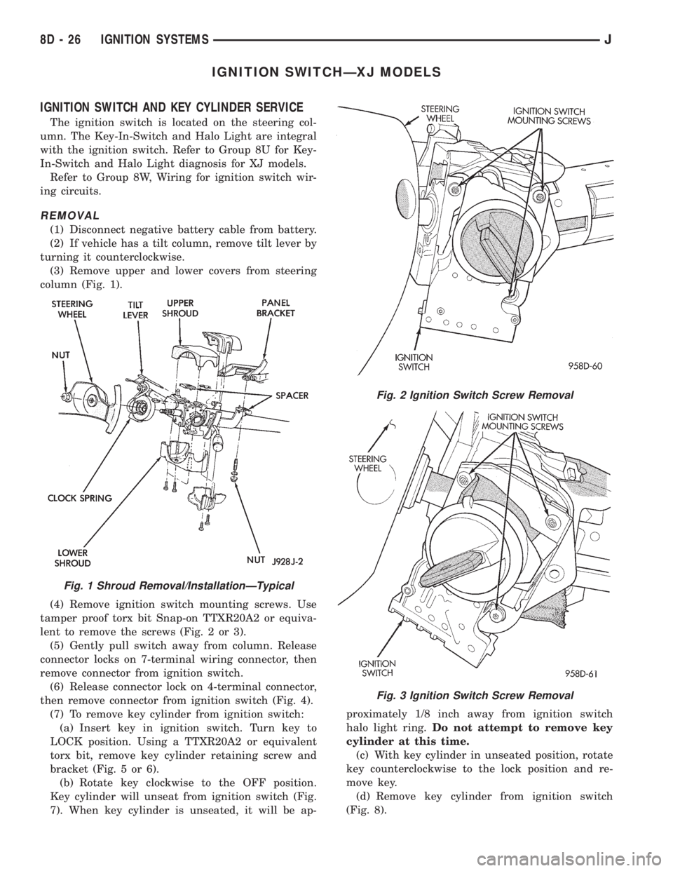
column (Fig. 1).
(4) Remove ignition switch mounting screws. Use
tamper proof torx bit Snap-on TTXR20A2 or equiva-
lent to remove the screws (Fig. 2 or 3).
(5) Gently pull switch away from column. Release
connector locks on 7-terminal wiring connector, then
remove connector from ignition switch.
(6) Release connector lock on 4-terminal connector,
then remove connector from ignition switch (Fig. 4).
(7) To remove key cylinder from ignition switch:
(a) Insert key in ignition switch. Turn key to
LOCK position. Using a TTXR20A2 or equivalent
torx bit, remove key cylinder retaining screw and
bracket (Fig. 5 or 6).
(b) Rotate key clockwise to the OFF position.
Key cylinder will unseat from ignition switch (Fig.
7). When key cylinder is unseated, it will be ap-proximately 1/8 inch away from ignition switch
halo light ring.Do not attempt to remove key
cylinder at this time.
(c) With key cylinder in unseated position, rotate
key counterclockwise to the lock position and re-
move key.
(d) Remove key cylinder from ignition switch
(Fig. 8).
Fig. 1 Shroud Removal/InstallationÐTypical
Fig. 2 Ignition Switch Screw Removal
Fig. 3 Ignition Switch Screw Removal
8D - 26 IGNITION SYSTEMSJ
Page 347 of 2198

HEADLAMP HIGH BEAM INDICATOR LAMP
The high beam indicator lamp is controlled by the
headlamp dimmer (multi-function) switch. One side
of the indicator bulb is grounded at all times. The
other side of the bulb receives battery feed through
the contacts of the dimmer switch when the multi-
function switch stalk is actuated to turn the head-
lamp high beams on. Refer to Group 8L - Lamps for
more information.
LOW FUEL WARNING LAMP
A Light-Emitting Diode (LED) on the face of the
fuel gauge will light when the fuel level falls below
approximately 4 gallons. A low fuel warning module
attached to the rear of the fuel gauge controls when
the LED will light. When the module senses 66.5
ohms or more resistance from the fuel level sending
unit for 10 continuous seconds, the LED will light.
When the module senses 63.5 ohms or less resistance
from the fuel level sending unit for 20 continuous
seconds, the LED is turned off.
LOW OIL PRESSURE WARNING LAMP
The low oil pressure warning lamp lights with the
ignition switch in the ON position and the engine not
running. The lamp should be off when the engine is
running. Battery voltage is supplied to one side of
the indicator bulb when the ignition switch is turned
ON. The warning lamp side of the combination oil
pressure sending unit is connected to the other side
of the bulb. When normal engine oil pressure is ap-
plied to the sending unit, resistance on the warning
lamp side is high and the lamp goes off. When engine
oil pressure is too low, resistance on the warning
lamp side of the sending unit is low, which causes
the bulb to light.
LOW WASHER FLUID WARNING LAMP
The low washer fluid warning lamp indicates when
the fluid level in the washer reservoir is too low. The
washer fluid level sensor uses a float in the reservoir
to monitor fluid level. The action of the float opens or
closes the switch within the sensor that provides ig-
nition-switched battery voltage to the lamp bulb. Re-
fer to Group 8K - Wiper and Washer Systems for
more information.
MALFUNCTION INDICATOR LAMP
The CHECK ENGINE or Malfunction Indicator
Lamp (MIL) lights each time the ignition switch is
turned ON, and stays on for 3 seconds as a bulb test.
If the Powertrain Control Module (PCM) receives an
incorrect signal or no signal from certain fuel oremission system related circuits or components, the
lamp is turned on. This will indicate that the PCM
has recorded a Diagnostic Trouble Code (DTC) in
electronic memory for a circuit or component mal-
function. Refer to Group 14 - Fuel System for more
information.
SEAT BELT REMINDER LAMP
The seat belt reminder lamp lights for 4 to 8 sec-
onds after the ignition switch is turned to the ON po-
sition. A timer in the chime/buzzer module controls
ignition-switched battery feed to the lamp. Refer to
Group 8U - Chime/Buzzer Warning Systems for more
information.
TURN SIGNAL INDICATOR LAMPS
The left and right turn signal indicator lamps are
controlled by the turn signal and hazard warning
(multi-function) switches. One side of the bulb for
each lamp is grounded at all times. The other side of
the bulb receives battery feed through the contacts of
the multi-function switch when the turn signal lever
(multi-function switch stalk) or hazard warning but-
ton are actuated. Refer to Group 8J - Turn Signal
and Hazard Warning Systems for more information.
UPSHIFT INDICATOR LAMP
Vehicles equipped with manual transmissions have
an optional upshift indicator lamp. Ground feed for
the lamp is switched by the Powertrain Control Mod-
ule (PCM). The lamp lights to indicate when the
driver should shift to the next highest gear for best
fuel economy. The PCM will turn the lamp off after 3
to 5 seconds if the upshift is not performed. The lamp
will remain off until the vehicle stops accelerating
and is brought back to the range of lamp operation,
or until the transmission is shifted into another gear.
The indicator lamp is normally on when the igni-
tion switch is turned ON and is turned off when the
engine is started. The lamp will be turned on during
vehicle operation according to engine speed and load.
CLUSTER ILLUMINATION LAMPS
All cluster illumination lamps receive battery feed
from the instrument lamps fuse in the fuseblock
module through the panel dimmer rheostat of the
headlamp switch. When the park or headlamps are
on, the cluster illumination lamps light. Illumination
brightness can be adjusted by rotating the headlamp
switch knob (clockwise to dim, counterclockwise to
brighten).
8E - 4 INSTRUMENT PANEL AND GAUGESÐXJJ
Page 359 of 2198
CLUSTER ILLUMINATION LAMPS
(1) Check fuse 19 (fuse 25 - RHD) in fuseblock
module. If OK, go to next step. If not OK, replace
fuse.
(2) Turn park lamps on at headlamp switch. Rotate
headlamp switch knob counterclockwise to just before
interior lamps detent. Check for battery voltage at
fuse 19 (fuse 25 - RHD) in fuseblock module. Rotate
headlamp switch clockwise while observing test volt-
meter. Reading should go from battery voltage to zero
volts. If OK, go to next step. If not OK, repair open
circuit to headlamp switch or refer to Group 8L -
Lamps to diagnose headlamp switch.
(3) Disconnect battery negative cable. Remove in-
strument cluster bezel and cluster assembly. Unplug
cluster connector A. Connect battery negative cable.Turn park lamps on at headlamp switch. Rotate
headlamp switch knob counterclockwise to just before
interior lamps detent. Check for battery voltage at
cavity A7 (cavity A6 - RHD) of cluster connector A. If
OK, go to next step. If not OK, repair open circuit to
fuse as required.
(4) Turn park lamps off. Disconnect battery nega-
tive cable. Remove fuse 19 (fuse 25 - RHD) from fuse-
block module. Probe cavity A7 (cavity A6 - RHD) of
cluster connector A. Check for continuity to a good
ground. There should be no continuity. If OK, go to
next step. If not OK, repair short circuit as required.
(5) Probe cavity A3 of cluster connector A. Check
for continuity to ground. There should be continuity.
If not OK, repair open circuit as required.
8E - 16 INSTRUMENT PANEL AND GAUGESÐXJJ
Page 388 of 2198
AUDIO SYSTEMS
CONTENTS
page page
DIAGNOSIS............................. 2
GENERAL INFORMATION.................. 1SERVICE PROCEDURES................... 6
GENERAL INFORMATION
Following are general descriptions of major compo-
nents used in XJ (Cherokee)/YJ (Wrangler) audio sys-
tems. Refer to Group 8W - Wiring Diagrams for
complete circuit descriptions and diagrams.
RADIOS
Radio options for the XJ and YJ models include an
AM/FM stereo or an AM/FM stereo/cassette receiver.
Both units are Electronically-Tuned Radios (ETR)
and include a clock function. For more information
on radio features, setting procedures, and control
functions refer to the owner's manual.
IN-LINE FUSE
Each radio receives fused battery feed when the ig-
nition switch is in the ON or ACCESSORY position.
There is an additional in-line fuse in the back of the
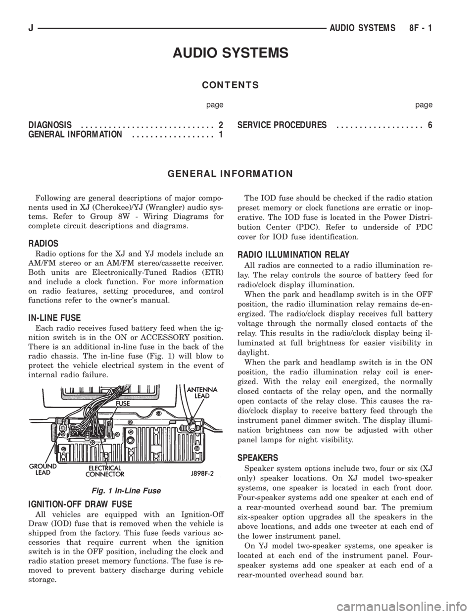
radio chassis. The in-line fuse (Fig. 1) will blow to
protect the vehicle electrical system in the event of
internal radio failure.
IGNITION-OFF DRAW FUSE
All vehicles are equipped with an Ignition-Off
Draw (IOD) fuse that is removed when the vehicle is
shipped from the factory. This fuse feeds various ac-
cessories that require current when the ignition
switch is in the OFF position, including the clock and
radio station preset memory functions. The fuse is re-
moved to prevent battery discharge during vehicle
storage.The IOD fuse should be checked if the radio station
preset memory or clock functions are erratic or inop-
erative. The IOD fuse is located in the Power Distri-
bution Center (PDC). Refer to underside of PDC
cover for IOD fuse identification.
RADIO ILLUMINATION RELAY
All radios are connected to a radio illumination re-
lay. The relay controls the source of battery feed for
radio/clock display illumination.
When the park and headlamp switch is in the OFF
position, the radio illumination relay remains de-en-
ergized. The radio/clock display receives full battery
voltage through the normally closed contacts of the
relay. This results in the radio/clock display being il-
luminated at full brightness for easier visibility in
daylight.
When the park and headlamp switch is in the ON
position, the radio illumination relay coil is ener-
gized. With the relay coil energized, the normally
closed contacts of the relay open, and the normally
open contacts of the relay close. This causes the ra-
dio/clock display to receive battery feed through the
instrument panel dimmer switch. The display illumi-
nation brightness can now be adjusted with other
panel lamps for night visibility.
SPEAKERS
Speaker system options include two, four or six (XJ
only) speaker locations. On XJ model two-speaker
systems, one speaker is located in each front door.
Four-speaker systems add one speaker at each end of
a rear-mounted overhead sound bar. The premium
six-speaker option upgrades all the speakers in the
above locations, and adds one tweeter at each end of
the lower instrument panel.
On YJ model two-speaker systems, one speaker is
located at each end of the instrument panel. Four-
speaker systems add one speaker at each end of a
rear-mounted overhead sound bar.
Fig. 1 In-Line Fuse
JAUDIO SYSTEMS 8F - 1
Page 391 of 2198
RADIO ILLUMINATION RELAY
If the relay fails any one of Relay Tests, it is faulty
and should be replaced. If the relay passes the Relay
Tests, proceed to the Relay Circuit Tests.
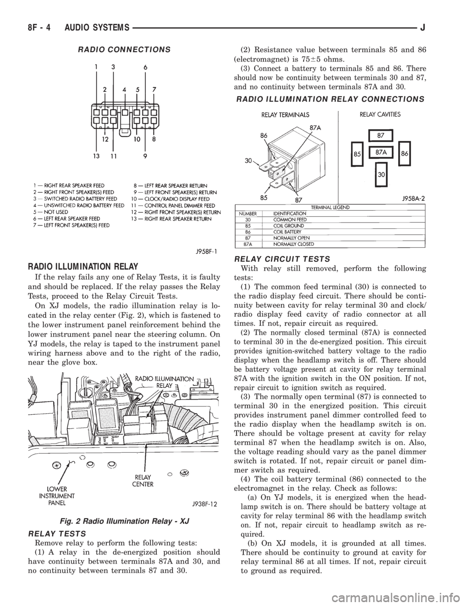
On XJ models, the radio illumination relay is lo-
cated in the relay center (Fig. 2), which is fastened to
the lower instrument panel reinforcement behind the
lower instrument panel near the steering column. On
YJ models, the relay is taped to the instrument panel
wiring harness above and to the right of the radio,
near the glove box.
RELAY TESTS
Remove relay to perform the following tests:
(1) A relay in the de-energized position should
have continuity between terminals 87A and 30, and
no continuity between terminals 87 and 30.(2) Resistance value between terminals 85 and 86
(electromagnet) is 7565 ohms.
(3) Connect a battery to terminals 85 and 86. There
should now be continuity between terminals 30 and 87,
and no continuity between terminals 87A and 30.
RELAY CIRCUIT TESTS
With relay still removed, perform the following
tests:
(1) The common feed terminal (30) is connected to
the radio display feed circuit. There should be conti-
nuity between cavity for relay terminal 30 and clock/
radio display feed cavity of radio connector at all
times. If not, repair circuit as required.
(2) The normally closed terminal (87A) is connected
to terminal 30 in the de-energized position. This circuit
provides ignition-switched battery voltage to the radio
display when the headlamp switch is off. There should
be battery voltage present at cavity for relay terminal
87A with the ignition switch in the ON position. If not,
repair circuit to ignition switch as required.
(3) The normally open terminal (87) is connected to
terminal 30 in the energized position. This circuit
provides instrument panel dimmer controlled feed to
the radio display when the headlamp switch is on.
There should be voltage present at cavity for relay
terminal 87 when the headlamp switch is on. Also,
the voltage reading should vary as the panel dimmer
switch is rotated. If not, repair circuit or panel dim-
mer switch as required.
(4) The coil battery terminal (86) connected to the
electromagnet in the relay. Check as follows:
(a) On YJ models, it is energized when the head-
lamp switch is on. There should be battery voltage at
cavity for relay terminal 86 with the headlamp switch
on. If not, repair circuit to headlamp switch as re-
quired.
(b) On XJ models, it is grounded at all times.
There should be continuity to ground at cavity for
relay terminal 86 at all times. If not, repair circuit
to ground as required.
RADIO CONNECTIONS
Fig. 2 Radio Illumination Relay - XJ
RADIO ILLUMINATION RELAY CONNECTIONS
8F - 4 AUDIO SYSTEMSJ
Page 400 of 2198
SERVICE PROCEDURES
HORN REMOVE/INSTALL
XJ
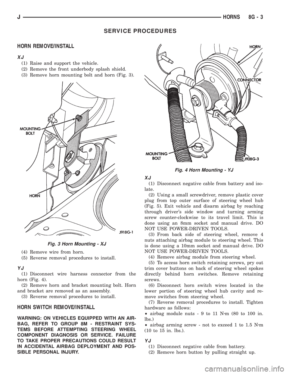
(1) Raise and support the vehicle.
(2) Remove the front underbody splash shield.
(3) Remove horn mounting bolt and horn (Fig. 3).
(4) Remove wire from horn.
(5) Reverse removal procedures to install.
YJ
(1) Disconnect wire harness connector from the
horn (Fig. 4).
(2) Remove horn and bracket mounting bolt. Horn
and bracket are removed as an assembly.
(3) Reverse removal procedures to install.
HORN SWITCH REMOVE/INSTALL
WARNING: ON VEHICLES EQUIPPED WITH AN AIR-
BAG, REFER TO GROUP 8M - RESTRAINT SYS-
TEMS BEFORE ATTEMPTING STEERING WHEEL
COMPONENT DIAGNOSIS OR SERVICE. FAILURE
TO TAKE PROPER PRECAUTIONS COULD RESULT
IN ACCIDENTAL AIRBAG DEPLOYMENT AND POS-
SIBLE PERSONAL INJURY.
XJ
(1) Disconnect negative cable from battery and iso-
late.
(2) Using a small screwdriver, remove plastic cover
plug from top outer surface of steering wheel hub
(Fig. 5). Exit vehicle and disarm airbag by reaching
through driver's side window and turning arming
screw counter-clockwise to its travel limit. This is
done using an 8mm socket and manual drive. DO
NOT USE POWER-DRIVEN TOOLS.
(3) From back side of steering wheel, remove 4
nuts attaching airbag module to steering wheel. This
is done using a 10mm socket and manual drive. DO
NOT USE POWER-DRIVEN TOOLS.
(4) Remove airbag module from steering wheel.
(5) To access horn switch retaining screws, pry out
trim cover buttons on back of steering wheel spokes
directly behind horn switches. Remove retaining
screws.
(6) Disconnect horn switch wires located in the
lower portion of steering wheel hub cavity and re-
move switches from steering wheel.
(7) Reverse removal procedures to install. Tighten
hardware as follows:
²airbag module nuts-9to11Nzm (80 to 100 in.
lbs.)
²airbag arming screw - not to exceed 1 to 1.5 Nzm
(10 to 15 in. lbs.).
YJ
(1) Disconnect negative cable from battery.
(2) Remove horn button by pulling straight up.
Fig. 3 Horn Mounting - XJ
Fig. 4 Horn Mounting - YJ
JHORNS 8G - 3