1995 JEEP CHEROKEE ECU
[x] Cancel search: ECUPage 134 of 2198
(2) Inspect clutch pack plates for wear, scoring or
damage. Replace both clutch packs if any one compo-
nent in either pack is damaged.
(3) Inspect side and pinion gears. Replace any gear
that is worn, cracked, chipped or damaged.
(4) Inspect differential case and pinion shaft. Re-
place if worn or damaged.
PRESOAK PLATES AND DISC
Plates and dics with fiber coating (no groves or
lines) must be presoaked in Friction Modifier before
assembly. Soak plates and discs for a minimum of 20
minutes. Add remaining Friction Modifier to differen-
tial after assembly.
ASSEMBLY
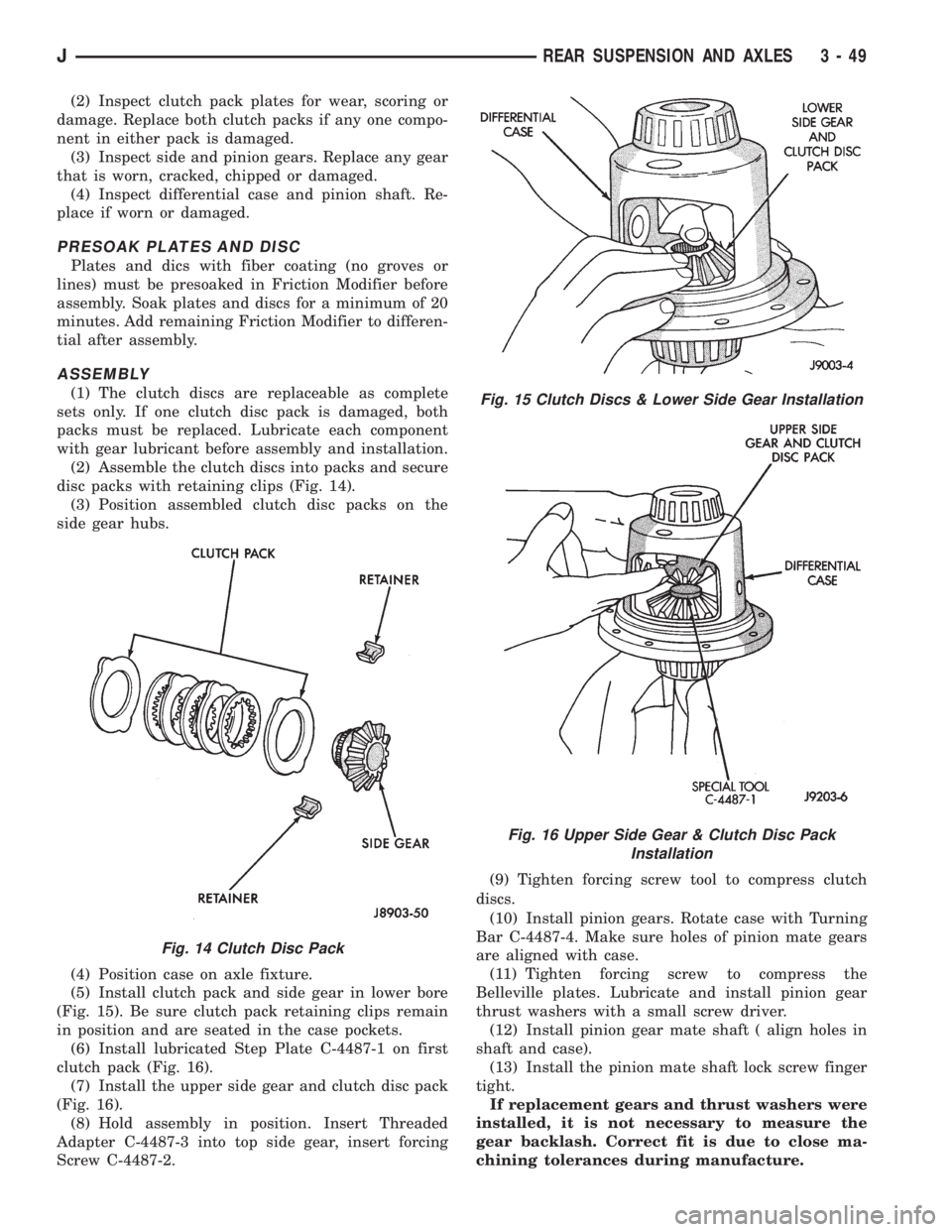
(1) The clutch discs are replaceable as complete
sets only. If one clutch disc pack is damaged, both
packs must be replaced. Lubricate each component
with gear lubricant before assembly and installation.
(2) Assemble the clutch discs into packs and secure
disc packs with retaining clips (Fig. 14).
(3) Position assembled clutch disc packs on the
side gear hubs.
(4) Position case on axle fixture.
(5) Install clutch pack and side gear in lower bore
(Fig. 15). Be sure clutch pack retaining clips remain
in position and are seated in the case pockets.
(6) Install lubricated Step Plate C-4487-1 on first
clutch pack (Fig. 16).
(7) Install the upper side gear and clutch disc pack
(Fig. 16).
(8) Hold assembly in position. Insert Threaded
Adapter C-4487-3 into top side gear, insert forcing
Screw C-4487-2.(9) Tighten forcing screw tool to compress clutch
discs.
(10) Install pinion gears. Rotate case with Turning
Bar C-4487-4. Make sure holes of pinion mate gears
are aligned with case.
(11) Tighten forcing screw to compress the
Belleville plates. Lubricate and install pinion gear
thrust washers with a small screw driver.
(12) Install pinion gear mate shaft ( align holes in
shaft and case).
(13) Install the pinion mate shaft lock screw finger
tight.
If replacement gears and thrust washers were
installed, it is not necessary to measure the
gear backlash. Correct fit is due to close ma-
chining tolerances during manufacture.
Fig. 14 Clutch Disc Pack
Fig. 15 Clutch Discs & Lower Side Gear Installation
Fig. 16 Upper Side Gear & Clutch Disc Pack
Installation
JREAR SUSPENSION AND AXLES 3 - 49
Page 140 of 2198
ABS BRAKE DIAGNOSIS
INDEX
page page
ABS Diagnostic Connector................... 3
ABS Warning Light Display................... 3
Antilock ECU and Hcu Diagnosis............... 3
DRB Scan Tool............................ 3General Information........................ 3
Normal Operating Conditions.................. 3
Wheel/Tire Size and Input Signals.............. 3
GENERAL INFORMATION
The DRB scan tool is required for ABS diagnosis.
The scan tool is used to identify ABS circuit faults.
Once a faulty circuit has been identified, refer to
the appropriate chassis/body diagnostic manual for
individual component testing.
ABS WARNING LIGHT DISPLAY
The amber antilock light illuminates at startup as
part of the system self check feature. The light illu-
minates for 2-3 seconds then goes off as part of the
normal check routine.
An ABS circuit fault is indicated when the amber
light remains on after startup, or illuminates during
vehicle operation.
Verify that a fault is actually related to the ABS
system before making repairs. For example, if the
red warning illuminates but the ABS light does not,
the problem is related to a service brake component
and not the ABS system. Or, if neither light illumi-
nates but a brake problem is noted, again, the prob-
lem is with a service brake component and not with
the ABS system.
ABS DIAGNOSTIC CONNECTOR
The ABS diagnostic connector is inside the vehicle.
The connector is the access point for the DRB scan tool.
On XJ models, the connector is located under the
instrument panel to the right of the steering column.
On some models, the connecter may be tucked under
the carpeting on the transmission tunnel. The con-
necter is a black, 6-way type.
On YJ models, the connector is under the instru-
ment panel by the the driver side kick panel. The
connecter is a black, 6 or 8-way type.
The DRB scan tool kit contains adapter cords for
both types of connecter. Use the appropriate cord for
test hookup.
DRB SCAN TOOL
ABS diagnosis is performed with the DRB scan tool.
Refer to the DRB scan tool manual for test hookup and
procedures. Diagnosis information is provided in the ap-
propriate chassis/body diagnostic manual.
WHEEL/TIRE SIZE AND INPUT SIGNALS
Antilock system operation is dependant on accurate
signals from the wheel speed sensors. Ideally, the ve-
hicle wheels and tires should all be the same size
and type. However, the Jeep ABS system is designed
to operate with a compact spare tire installed.
NORMAL OPERATING CONDITIONS
Sound Levels
The hydraulic control unit pump and solenoid valves
may produce some sound as they cycle on and off. This
is a normal condition and should not be mistaken for
faulty operation. Under most conditions, pump and so-
lenoid valve operating sounds will not be audible.
Vehicle Response In Antilock Mode
During antilock braking, the hydraulic control unit
solenoid valves cycle rapidly in response to antilock
electronic control unit signals.
The driver will experience a pulsing sensation
within the vehicle as the solenoids decrease, hold, or
increase pressure as needed. Brake pedal pulsing will
also be noted and is anormal condition.
Steering Response
A modest amount of steering input is required dur-
ing extremely high deceleration braking, or when
braking on differing traction surfaces. An example of
differing traction surfaces would be when the left
side wheels are on ice and the right side wheels are
on dry pavement.
Owner Induced Faults
Driving away with the parking brakes still applied
will cause warning light illumination. Pumping the
brake pedal will also generate a system fault and in-
terfere with ABS system operation.
ANTILOCK ECU AND HCU DIAGNOSIS
An ECU or HCU fault can only be determined
through testing with the DRB scan tool. Do not re-
place either component unless a fault is actually in-
dicated.
JABS BRAKE DIAGNOSIS 5 - 3
Page 144 of 2198
fied. This causes pull to switch direction in favor of
the brake unit that is functioning normally.
When diagnosing a change in pull condition, re-
member that pull will return to the original direction
if the dragging brake unit is allowed to cool down
(and is not seriously damaged).
REAR BRAKE GRAB
Rear grab (or pull) is usually caused by contami-
nated lining, bent or binding shoes and support
plates, or improperly assembled components. This is
particularly true when only one rear wheel is in-
volved. However, when both rear wheels are affected,
the master cylinder could be at fault.
BRAKES DO NOT HOLD AFTER DRIVING THROUGH
DEEP WATER PUDDLES
This condition is caused by water soaked lining. If
the lining is only wet, it can be dried by driving with
the brakes lightly applied for a mile or two. However,
if the lining is both wet and dirty, disassembly and
cleaning will be necessary.
CONTAMINATED BRAKELINING
Brakelining contaminated by water is salvageable.
The lining can either be air dried or dried using heat.
In cases where brakelining is contaminated by oil,
grease, or brake fluid, the lining should be replaced.
Replacement is especially necessary when fluids/lu-
bricants have actually soaked into the lining mate-
rial. However, grease or dirt that gets onto the lining
surface (from handling) during brake repairs, can be
cleaned off. Spray the lining surface clean with Mo-
par brake cleaner.
BRAKE FLUID CONTAMINATION
There are two basic causes of brake fluid contami-
nation. The first involves allowing dirt, debris, or
other materials to enter the cylinder reservoirs when
the cover is off. The second involves adding non-rec-
ommended fluids to the cylinder reservoirs.
Brake fluid contaminated with only dirt, or debris
usually retains a normal appearance. In some cases,
the foreign material will remain suspended in the
fluid and be visible. The fluid and foreign material
can be removed from the reservoir with a suction gun
but only if the brakes have not been applied. If the
brakes are applied after contamination, system flush-
ing will be required. The master cylinder may also
have to be disassembled, cleaned and the piston seals
replaced. Foreign material lodged in the reservoir
compensator/return ports can cause brake drag by re-
stricting fluid return after brake application.
Brake fluid contaminated by a non-recommended
fluid may appear discolored, milky, oily looking, or
foamy. However, remember that brake fluid will
darken in time and occasionally be cloudy in appear-ance. These are normal conditions and should not be
mistaken for contamination.
If some type of oil has been added to the system,
the fluid will separate into distinct layers. To verify
this, drain off a sample with a clean suction gun.
Then pour the sample into a glass container and ob-
serve fluid action. If the fluid separates into distinct
layers, it is definitely contaminated.
The only real correction for contamination by non-
recommended fluid is to flush the entire hydraulic
system and replace all the seals.
BRAKE NOISE
Squeak/Squeal
Factory installed brakelining is made from as-
bestos free materials. These materials have dif-
ferent operating characteristics than previous
lining material. Under certain conditions, as-
bestos free lining may generate some squeak,
groan or chirp noise. This noise is considered
normal and does not indicate a problem. The
only time inspection is necessary, is when noise
becomes constant or when grinding, scraping
noises occur.
Constant brake squeak or squeal may be due to lin-
ings that are wet or contaminated with brake fluid,
grease, or oil. Glazed linings, rotors/drums with hard
spots, and dirt/foreign material embedded in the
brake lining also cause squeak. Loud squeak, squeal,
scraping, or grinding sounds are a sign of severely
worn brake lining. If the lining has worn completely
through in spots, metal-to-metal contact occurs.
Thump/Clunk
Thumping or clunk noises during braking are fre-
quentlynotcaused by brake components. In many
cases, such noises are caused by loose or damaged
steering, suspension, or engine components. However,
calipers that bind on the slide surfaces can generate
a thump or clunk noise. In addition, worn out, im-
properly adjusted, or improperly assembled rear
brakeshoes can also produce a thump noise.
Chatter/Shudder
Brake chatter, or shudder is usually caused by
loose or worn components, or glazed/burnt lining. Ro-
tors with hard spots can also contribute to chatter.
Additional causes of chatter are out of tolerance ro-
tors, brake lining not securely attached to the shoes,
loose wheel bearings and contaminated brake lining.
WHEEL AND TIRE PROBLEMS
Some conditions attributed to brake components
may actually be caused by a wheel or tire problem.
A damaged wheel can cause shudder, vibration and
pull. A worn or damaged tire can also cause pull.
Severely worn tires with very little tread left can
JSERVICE BRAKE DIAGNOSIS 5 - 7
Page 145 of 2198
produce a condition similar to grab as the tire loses
and recovers traction.
Flat-spotted tires can cause vibration and wheel
tramp and generate shudder during brake operation.
A tire with internal damage such as a severe bruise
or ply separation can cause vibration and pull. The
pull will be magnified when braking.
DIAGNOSING PARKING BRAKE MALFUNCTIONS
Adjustment Mechanism
Parking brake adjustment is controlled by a ca-
ble tensioner mechanism. The cable tensioner,
once adjusted at the factory, will not need further
attention under normal circumstances. There are
only two instances when adjustment is required.
The first is when a new tensioner, or cables have
been installed. And the second, is when the ten-
sioner and cables are disconnected for access to
other brake components.
Parking Brake Switch And Warning Light Illumination
The parking brake switch on the lever, or foot
pedal, is in circuit with the red warning light. The
switch will illuminate the red light only when the
parking brakes are applied. If the light remains on
after parking brake release, the switch or wires are
faulty, or cable tensioner adjustment is incorrect.
If the red light comes on while the vehicle is in mo-
tion and brake pedal height decreases, a fault has oc-
curred in the front or rear brake hydraulic system.
Parking Brake problem Causes
In most cases, the actual cause of an improperly
functioning parking brake (too loose/too tight/wont
hold), can be traced to a drum brake component.
The leading cause of improper parking brake
operation, is excessive clearance between the
brakeshoes and the drum surface. Excessive
clearance is a result of: lining and/or drum
wear; oversize drums; or inoperative shoe ad-
juster components.
Excessive parking brake lever travel (sometimes de-
scribed as a loose lever or too loose condition), is the re-
sult of worn brakeshoes/drums, improper brakeshoe
adjustment, or incorrectly assembled brake parts.
A ``too loose'' condition can also be caused by inop-
erative brakeshoe adjusters. If the adjusters are mis-
assembled, they will not function. In addition, since
the adjuster mechanism only works during reverse
stops, it is important that complete stops be made.
The adjuster mechanism does not operate when roll-
ing stops are made in reverse. The vehicle must be
brought to a complete halt before the adjuster lever
will turn the adjuster screw.
A condition where the parking brakes do not hold, will
most probably be due to a wheel brake component.
Items to look for when diagnosing a parking brake
problem, are:
²rear brakeshoe wear or adjuster problem
²rear brake drum wear
²brake drums machined beyond allowable diameter
(oversize)
²parking brake front cable not secured to lever
²parking brake rear cable seized
²parking brake strut reversed
²parking brake strut not seated in both shoes
²parking brake lever not seated in secondary shoe
²parking brake lever or brakeshoe bind on support
plate
²brakeshoes reversed
²adjuster screws seized
²adjuster screws reversed
²holddown or return springs misassembled or lack
tension
²wheel cylinder pistons seized
Brake drums that are machined oversize are diffi-
cult to identify without inspection. If oversize drums
are suspected, diameter of the braking surface will
have to be checked with an accurate drum gauge.
Oversize drums will cause low brake pedal and lack
of parking brake holding ability.
Improper parking brake strut and lever installation
will result in unsatisfactory parking brake operation.
Intermixing the adjuster screws will cause drag, bind
and pull along with poor parking brake operation.
Parking brake adjustment and parts replacement pro-
cedures are described in the Parking Brake section.
MASTER CYLINDER/POWER BOOSTER TEST
(1) Start engine and check booster vacuum hose
connections. Hissing noise indicates vacuum leak.
Correct any vacuum leak before proceeding.
(2) Stop engine and shift transmission into Neu-
tral.
(3) Pump brake pedal until all vacuum reserve in
booster is depleted.
(4) Press and hold brake pedal under light foot
pressure.
(a) If pedal holds firm, proceed to step (5).
(b) If pedal does not hold firm and falls away,
master cylinder is faulty due to internal leakage.
Overhaul or replace cylinder.
(5) Start engine and note pedal action.
(a) If pedal falls away slightly under light foot
pressure then holds firm, proceed to step (6).
(b) If no pedal action is discernible, or hard pedal
is noted, power booster or vacuum check valve is
faulty. Install known good check valve and repeat
steps (2) through (5).
(6) Rebuild booster vacuum reserve as follows: Re-
lease brake pedal. Increase engine speed to 1500
rpm, close throttle and immediately turn off ignition.
5 - 8 SERVICE BRAKE DIAGNOSISJ
Page 154 of 2198
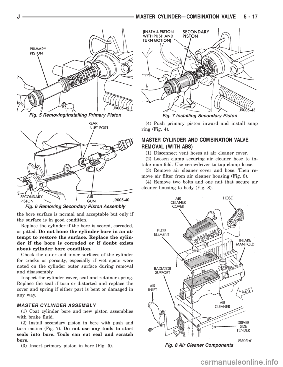
the bore surface is normal and acceptable but only if
the surface is in good condition.
Replace the cylinder if the bore is scored, corroded,
or pitted.Do not hone the cylinder bore in an at-
tempt to restore the surface. Replace the cylin-
der if the bore is corroded or if doubt exists
about cylinder bore condition.
Check the outer and inner surfaces of the cylinder
for cracks or porosity, especially if wet spots were
noted on the cylinder outer surface during removal
and disassembly.
Inspect the cylinder cover, seal and retainer spring.
Replace the seal if torn or distorted and replace the
cover and spring if either part is bent or damaged in
any way.
MASTER CYLINDER ASSEMBLY
(1) Coat cylinder bore and new piston assemblies
with brake fluid.
(2) Install secondary piston in bore with push and
turn motion (Fig. 7).Do not use any tools to start
seals into bore. Tools can cut seal and scratch
bore.
(3) Insert primary piston in bore (Fig. 5).(4) Push primary piston inward and install snap
ring (Fig. 4).
MASTER CYLINDER AND COMBINATION VALVE
REMOVAL (WITH ABS)
(1) Disconnect vent hoses at air cleaner cover.
(2) Loosen clamp securing air cleaner hose to in-
take manifold. Use screwdriver to tap clamp loose.
(3) Remove air cleaner cover and hose. Then re-
move air filter from air cleaner housing (Fig. 8).
(4) Remove two bolts and one nut that secure air
cleaner housing to body (Fig. 8).
Fig. 8 Air Cleaner Components
Fig. 5 Removing/Installing Primary Piston
Fig. 6 Removing Secondary Piston Assembly
Fig. 7 Installing Secondary Piston
JMASTER CYLINDERÐCOMBINATION VALVE 5 - 17
Page 155 of 2198
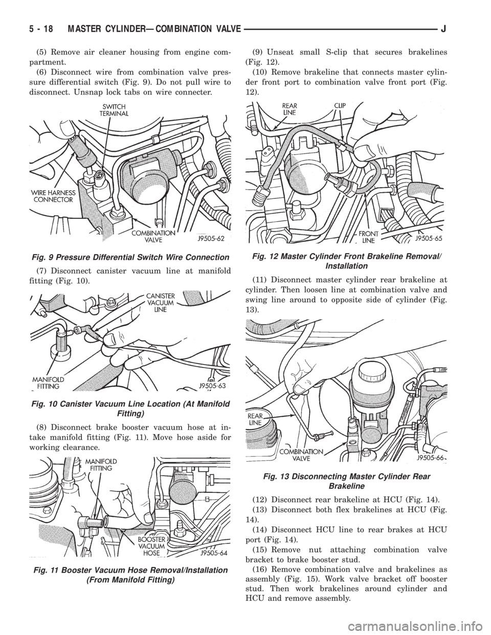
(5) Remove air cleaner housing from engine com-
partment.
(6) Disconnect wire from combination valve pres-
sure differential switch (Fig. 9). Do not pull wire to
disconnect. Unsnap lock tabs on wire connecter.
(7) Disconnect canister vacuum line at manifold
fitting (Fig. 10).
(8) Disconnect brake booster vacuum hose at in-
take manifold fitting (Fig. 11). Move hose aside for
working clearance.(9) Unseat small S-clip that secures brakelines
(Fig. 12).
(10) Remove brakeline that connects master cylin-
der front port to combination valve front port (Fig.
12).
(11) Disconnect master cylinder rear brakeline at
cylinder. Then loosen line at combination valve and
swing line around to opposite side of cylinder (Fig.
13).
(12) Disconnect rear brakeline at HCU (Fig. 14).
(13) Disconnect both flex brakelines at HCU (Fig.
14).
(14) Disconnect HCU line to rear brakes at HCU
port (Fig. 14).
(15) Remove nut attaching combination valve
bracket to brake booster stud.
(16) Remove combination valve and brakelines as
assembly (Fig. 15). Work valve bracket off booster
stud. Then work brakelines around cylinder and
HCU and remove assembly.
Fig. 9 Pressure Differential Switch Wire Connection
Fig. 10 Canister Vacuum Line Location (At Manifold
Fitting)
Fig. 11 Booster Vacuum Hose Removal/Installation
(From Manifold Fitting)
Fig. 12 Master Cylinder Front Brakeline Removal/
Installation
Fig. 13 Disconnecting Master Cylinder Rear
Brakeline
5 - 18 MASTER CYLINDERÐCOMBINATION VALVEJ
Page 161 of 2198
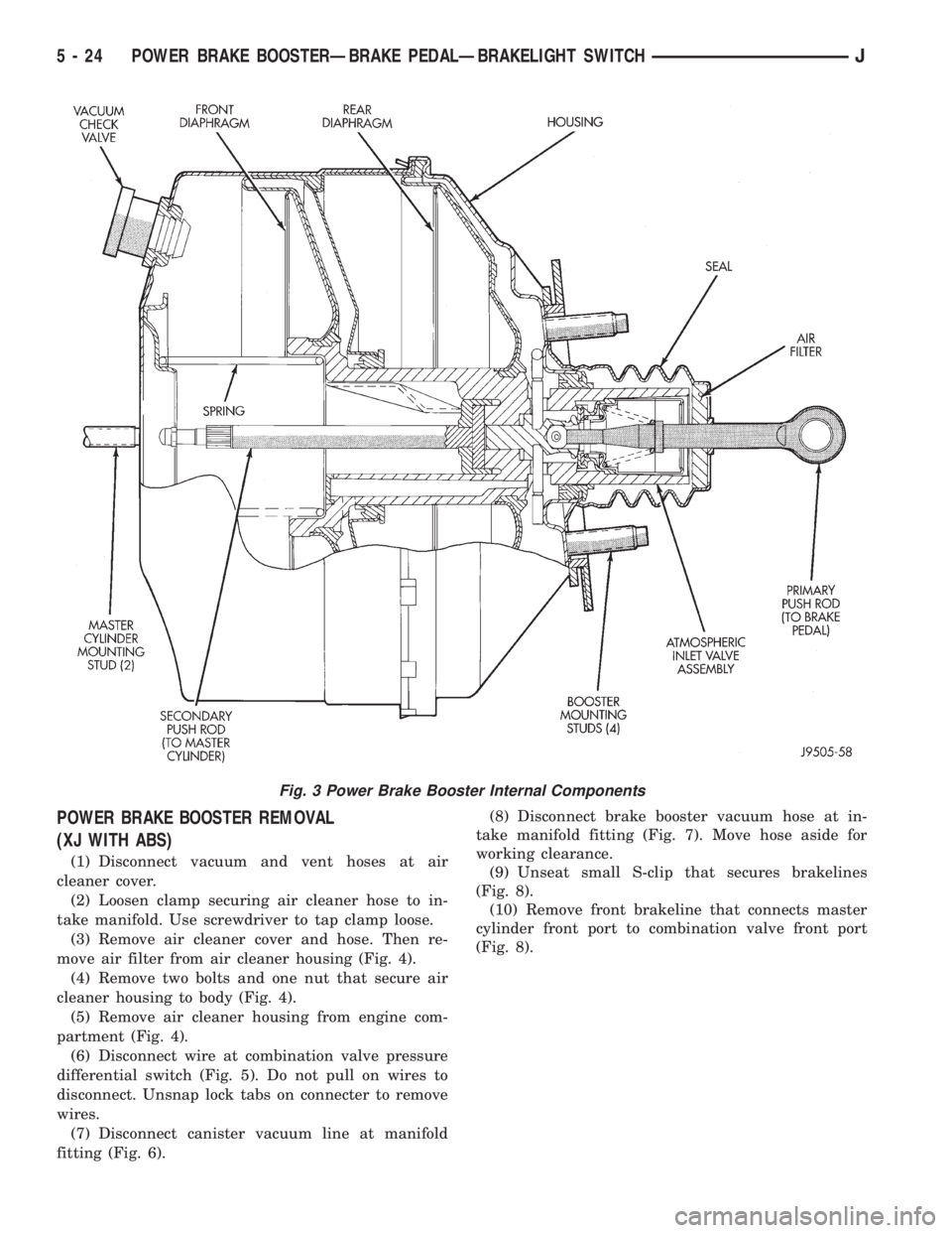
POWER BRAKE BOOSTER REMOVAL
(XJ WITH ABS)
(1) Disconnect vacuum and vent hoses at air
cleaner cover.
(2) Loosen clamp securing air cleaner hose to in-
take manifold. Use screwdriver to tap clamp loose.
(3) Remove air cleaner cover and hose. Then re-
move air filter from air cleaner housing (Fig. 4).
(4) Remove two bolts and one nut that secure air
cleaner housing to body (Fig. 4).
(5) Remove air cleaner housing from engine com-
partment (Fig. 4).
(6) Disconnect wire at combination valve pressure
differential switch (Fig. 5). Do not pull on wires to
disconnect. Unsnap lock tabs on connecter to remove
wires.
(7) Disconnect canister vacuum line at manifold
fitting (Fig. 6).(8) Disconnect brake booster vacuum hose at in-
take manifold fitting (Fig. 7). Move hose aside for
working clearance.
(9) Unseat small S-clip that secures brakelines
(Fig. 8).
(10) Remove front brakeline that connects master
cylinder front port to combination valve front port
(Fig. 8).
Fig. 3 Power Brake Booster Internal Components
5 - 24 POWER BRAKE BOOSTERÐBRAKE PEDALÐBRAKELIGHT SWITCHJ
Page 163 of 2198
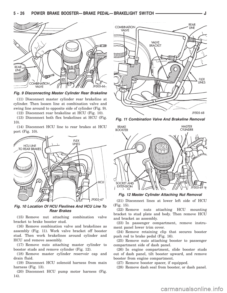
(11) Disconnect master cylinder rear brakeline at
cylinder. Then loosen line at combination valve and
swing line around to opposite side of cylinder (Fig. 9).
(12) Disconnect rear brakeline at HCU (Fig. 10).
(13) Disconnect both flex brakelines at HCU (Fig.
10).
(14) Disconnect HCU line to rear brakes at HCU
port (Fig. 10).
(15) Remove nut attaching combination valve
bracket to brake booster stud.
(16) Remove combination valve and brakelines as
assembly (Fig. 11). Work valve bracket off booster
stud. Then work brakelines around cylinder and
HCU and remove assembly.
(17) Remove nuts attaching master cylinder to
booster studs and remove cylinder (Fig. 12).
(18) Remove master cylinder reservoir cap and
drain fluid.
(19) Disconnect HCU solenoid harness from main
harness (Fig. 13).
(20) Disconnect HCU pump motor harness (Fig.
14).(21) Disconnect lines at lower left side of HCU
(Fig. 15).
(22) Remove nuts attaching HCU mounting
bracket to stud plate and body. Then remove HCU
and bracket as assembly.
(23) In passenger compartment, remove instru-
ment panel lower trim cover.
(24) Remove retaining clip that secures booster
push rod to brake pedal (Fig. 16).
(25) Remove nuts attaching booster to passenger
compartment side of dash panel.
(26) In engine compartment, slide booster studs
out of dash panel, tilt booster upward, and remove
booster from engine compartment.
(27) Remove booster spacer, if equipped.
(28) Remove dash seal from booster, or dash panel.
Fig. 9 Disconnecting Master Cylinder Rear Brakeline
Fig. 10 Location Of HCU Flexlines And HCU Line To
Rear Brakes
Fig. 11 Combination Valve And Brakeline Removal
Fig. 12 Master Cylinder Attaching Nut Removal
5 - 26 POWER BRAKE BOOSTERÐBRAKE PEDALÐBRAKELIGHT SWITCHJ