1995 JEEP CHEROKEE Conditioner
[x] Cancel search: ConditionerPage 1158 of 2198
LEAK-DOWN TEST
After cleaning and inspection, test each tappet for
specified leak-down rate tolerance to ensure zero-lash
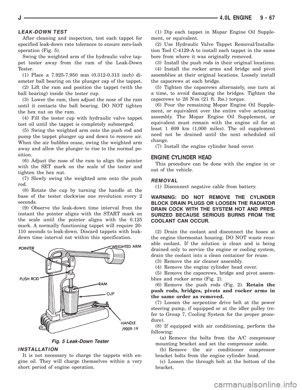
operation (Fig. 5).
Swing the weighted arm of the hydraulic valve tap-
pet tester away from the ram of the Leak-Down
Tester.
(1) Place a 7.925-7.950 mm (0.312-0.313 inch) di-
ameter ball bearing on the plunger cap of the tappet.
(2) Lift the ram and position the tappet (with the
ball bearing) inside the tester cup.
(3) Lower the ram, then adjust the nose of the ram
until it contacts the ball bearing. DO NOT tighten
the hex nut on the ram.
(4) Fill the tester cup with hydraulic valve tappet
test oil until the tappet is completely submerged.
(5) Swing the weighted arm onto the push rod and
pump the tappet plunger up and down to remove air.
When the air bubbles cease, swing the weighted arm
away and allow the plunger to rise to the normal po-
sition.
(6) Adjust the nose of the ram to align the pointer
with the SET mark on the scale of the tester and
tighten the hex nut.
(7) Slowly swing the weighted arm onto the push
rod.
(8) Rotate the cup by turning the handle at the
base of the tester clockwise one revolution every 2
seconds.
(9) Observe the leak-down time interval from the
instant the pointer aligns with the START mark on
the scale until the pointer aligns with the 0.125
mark. A normally functioning tappet will require 20-
110 seconds to leak-down. Discard tappets with leak-
down time interval not within this specification.
INSTALLATION
It is not necessary to charge the tappets with en-
gine oil. They will charge themselves within a very
short period of engine operation.(1) Dip each tappet in Mopar Engine Oil Supple-
ment, or equivalent.
(2) Use Hydraulic Valve Tappet Removal/Installa-
tion Tool C-4129-A to install each tappet in the same
bore from where it was originally removed.
(3) Install the push rods in their original locations.
(4) Install the rocker arms and bridge and pivot
assemblies at their original locations. Loosely install
the capscrews at each bridge.
(5) Tighten the capscrews alternately, one turn at
a time, to avoid damaging the bridges. Tighten the
capscrews to 28 Nzm (21 ft. lbs.) torque.
(6) Pour the remaining Mopar Engine Oil Supple-
ment, or equivalent over the entire valve actuating
assembly. The Mopar Engine Oil Supplement, or
equivalent must remain with the engine oil for at
least 1 609 km (1,000 miles). The oil supplement
need not be drained until the next scheduled oil
change.
(7) Install the engine cylinder head cover.
ENGINE CYLINDER HEAD
This procedure can be done with the engine in or
out of the vehicle.
REMOVAL
(1) Disconnect negative cable from battery.
WARNING: DO NOT REMOVE THE CYLINDER
BLOCK DRAIN PLUGS OR LOOSEN THE RADIATOR
DRAIN COCK WITH THE SYSTEM HOT AND PRES-
SURIZED BECAUSE SERIOUS BURNS FROM THE
COOLANT CAN OCCUR.
(2) Drain the coolant and disconnect the hoses at
the engine thermostat housing. DO NOT waste reus-
able coolant. If the solution is clean and is being
drained only to service the engine or cooling system,
drain the coolant into a clean container for reuse.
(3) Remove the air cleaner assembly.
(4) Remove the engine cylinder head cover.
(5) Remove the capscrews, bridge and pivot assem-
blies and rocker arms (Fig. 2).
(6) Remove the push rods (Fig. 2).Retain the
push rods, bridges, pivots and rocker arms in
the same order as removed.
(7) Loosen the serpentine drive belt at the power
steering pump, if equipped or at the idler pulley (re-
fer to Group 7, Cooling System for the proper proce-
dure).
(8) If equipped with air conditioning, perform the
following:
(a) Remove the bolts from the A/C compressor
mounting bracket and set the compressor aside.
(b) Remove the air conditioner compressor
bracket bolts from the engine cylinder head.
(c) Loosen the through bolt at the bottom of the
bracket.
Fig. 5 Leak-Down Tester
J4.0L ENGINE 9 - 67
Page 1160 of 2198
counter bolts which were painted in an earlier ser-
vice operation, replace them.
(6) Install the ignition coil and bracket assembly.
(7) Connect the temperature sending unit wire
connector.
(8) Install the spark plugs and tighten to 37 Nzm
(27 ft. lbs.) torque. Connect the ignition wires.
(9) Install the intake and engine exhaust mani-
folds (refer to Group 11, Exhaust System and Intake
Manifold for the proper procedures).
(10) Install the fuel lines and the vacuum advance
hose.
(11) If equipped, attach the power steering pump
and bracket.
(12) Install the push rods, rocker arms, pivots and
bridges in the order they were removed (refer to
Rocker Arms and Push Rods in this section).
(13) Install the engine cylinder head cover.
(14) Attach the air conditioner compressor mount-
ing bracket to the engine cylinder head and block.
Tighten the bolts to 40 Nzm (30 ft. lbs.) torque.
(15) Attach the air conditioning compressor to the
bracket. Tighten the bolts to 27 Nzm (20 ft. lbs.)
torque.
CAUTION: The serpentine drive belt must be routed
correctly. Incorrect routing can cause the water
pump to turn in the opposite direction causing the
engine to overheat.
(16) Install the serpentine drive belt and correctly
tension the belt (refer to Group 7, Cooling System for
the proper procedure).
(17) Install the air cleaner and ducting.
(18) Install the engine cylinder head cover.
(19) Connect the hoses to the engine thermostat
housing and fill the cooling system to the specified
level (refer to Group 7, Cooling Systems for the
proper procedure).
(20) The automatic transmission throttle linkage
and cable must be adjusted after completing the en-
gine cylinder head installation (refer to Group 21,
Transmissions for the proper procedures).(21) Install the temperature sending unit and con-
nect the wire connector.
(22) Connect the fuel line.
(23) Connect negative cable to battery.
(24) Connect the upper radiator hose and heater
hose at the engine thermostat housing.
(25) Fill the cooling system. Check for leaks.
WARNING: USE EXTREME CAUTION WHEN THE
ENGINE IS OPERATING. DO NOT STAND IN DIRECT
LINE WITH THE FAN. DO NOT PUT HANDS NEAR
THE PULLEYS, BELTS OR FAN. DO NOT WEAR
LOOSE CLOTHING.
(26) Operate the engine with the radiator cap off.
Inspect for leaks and continue operating the engine
until the engine thermostat opens. Add coolant, if re-
quired.
VALVES AND VALVE SPRINGS
This procedure is done with the engine cylinder
head removed from the block.
REMOVAL
(1) Remove the engine cylinder head from the cyl-
inder block.
(2) Use Valve Spring Compressor Tool
MD-998772A and compress each valve spring.
(3) Remove the valve locks, retainers, springs and
valve stem oil seals. Discard the oil seals.
(4) Use an Arkansas smooth stone or a jewelers
file to remove any burrs on the top of the valve stem,
especially around the groove for the locks.
(5) Remove the valves, and place them in a rack in
the same order as removed.
VALVE CLEANING
Clean all carbon deposits from the combustion
chambers, valve ports, valve stems, valve stem
guides and head.
Clean all grime and gasket material from the en-
gine cylinder head machined gasket surface.
INSPECTION
Inspect for cracks in the combustion chambers and
valve ports.
Inspect for cracks on the exhaust seat.
Inspect for cracks in the gasket surface at each
coolant passage.
Inspect valves for burned, cracked or warped
heads.
Inspect for scuffed or bent valve stems.
Replace valves displaying any damage.
VALVE REFACING
(1) Use a valve refacing machine to reface the in-
take and exhaust valves to the specified angle.
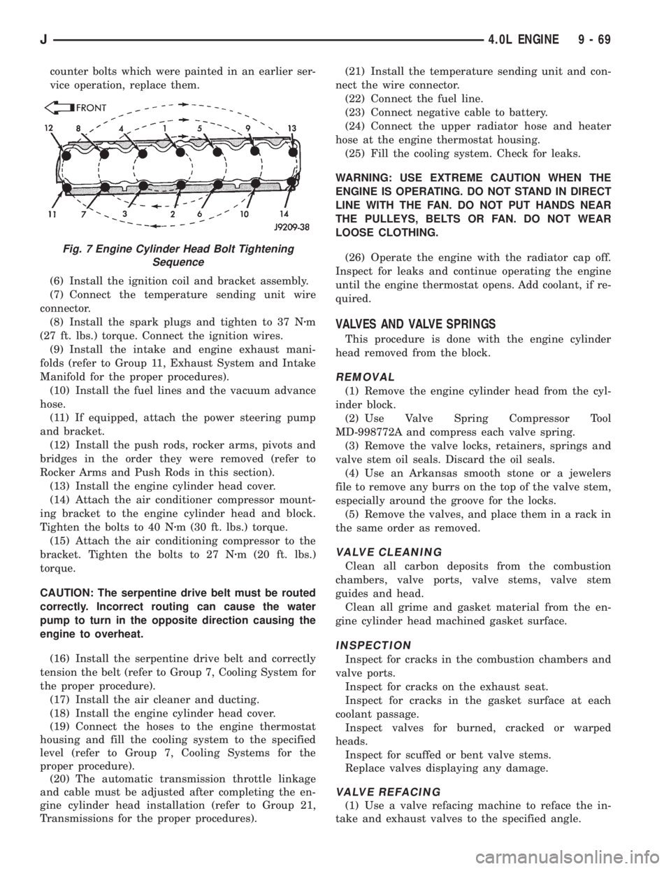
Fig. 7 Engine Cylinder Head Bolt Tightening
Sequence
J4.0L ENGINE 9 - 69
Page 1165 of 2198
properly aligned ensures correct valve timing. A worn
or stretched timing chain will adversely affect valve
timing. If the timing chain deflects more than 12.7
mm (1/2 inch) replace it. The correct timing chain
has 48 pins. A chain with more than 48 pins will
cause excessive slack.
INSTALLATION
Assemble the timing chain, crankshaft sprocket
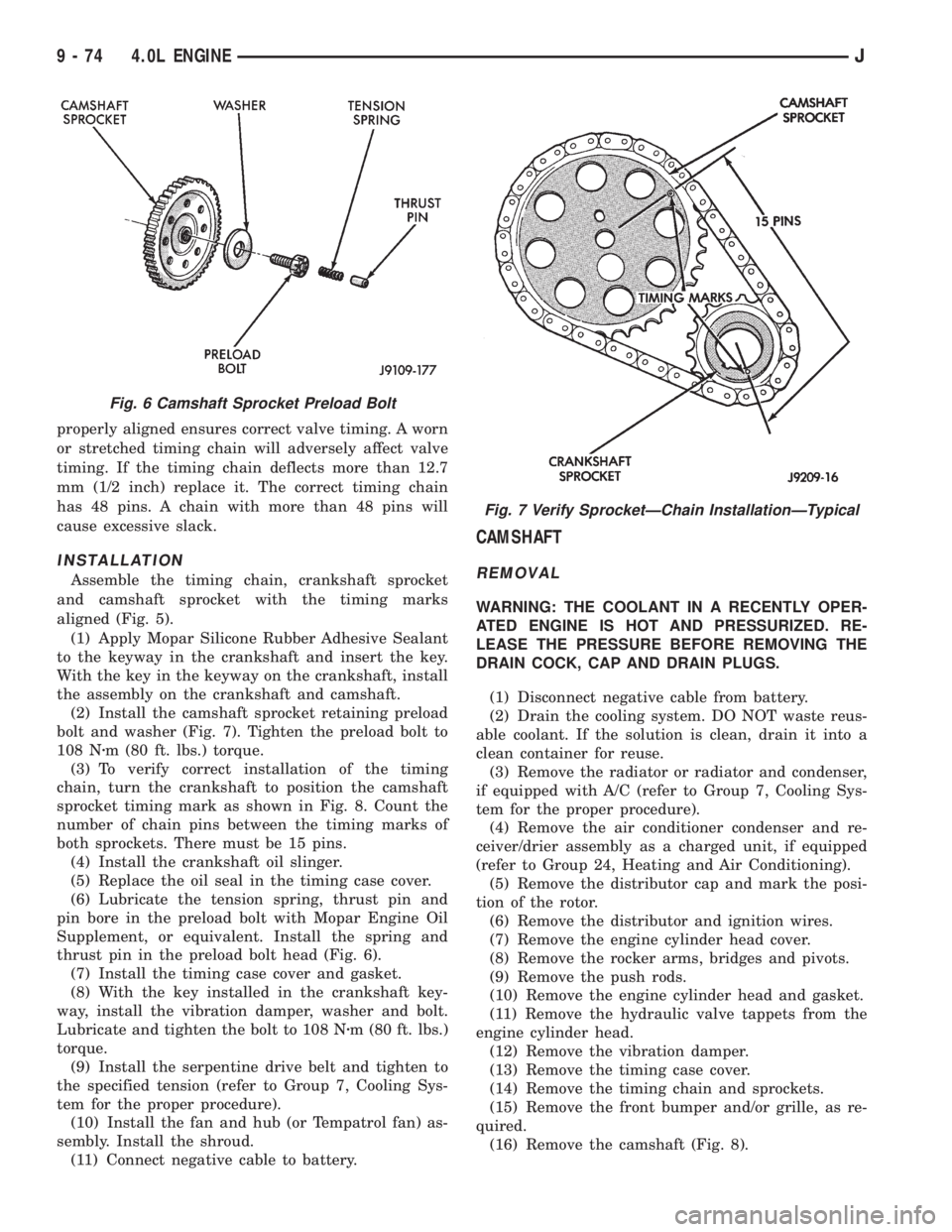
and camshaft sprocket with the timing marks
aligned (Fig. 5).
(1) Apply Mopar Silicone Rubber Adhesive Sealant
to the keyway in the crankshaft and insert the key.
With the key in the keyway on the crankshaft, install
the assembly on the crankshaft and camshaft.
(2) Install the camshaft sprocket retaining preload
bolt and washer (Fig. 7). Tighten the preload bolt to
108 Nzm (80 ft. lbs.) torque.
(3) To verify correct installation of the timing
chain, turn the crankshaft to position the camshaft
sprocket timing mark as shown in Fig. 8. Count the
number of chain pins between the timing marks of
both sprockets. There must be 15 pins.
(4) Install the crankshaft oil slinger.
(5) Replace the oil seal in the timing case cover.
(6) Lubricate the tension spring, thrust pin and
pin bore in the preload bolt with Mopar Engine Oil
Supplement, or equivalent. Install the spring and
thrust pin in the preload bolt head (Fig. 6).
(7) Install the timing case cover and gasket.
(8) With the key installed in the crankshaft key-
way, install the vibration damper, washer and bolt.
Lubricate and tighten the bolt to 108 Nzm (80 ft. lbs.)
torque.
(9) Install the serpentine drive belt and tighten to
the specified tension (refer to Group 7, Cooling Sys-
tem for the proper procedure).
(10) Install the fan and hub (or Tempatrol fan) as-
sembly. Install the shroud.
(11) Connect negative cable to battery.
CAMSHAFT
REMOVAL
WARNING: THE COOLANT IN A RECENTLY OPER-
ATED ENGINE IS HOT AND PRESSURIZED. RE-
LEASE THE PRESSURE BEFORE REMOVING THE
DRAIN COCK, CAP AND DRAIN PLUGS.
(1) Disconnect negative cable from battery.
(2) Drain the cooling system. DO NOT waste reus-
able coolant. If the solution is clean, drain it into a
clean container for reuse.
(3) Remove the radiator or radiator and condenser,
if equipped with A/C (refer to Group 7, Cooling Sys-
tem for the proper procedure).
(4) Remove the air conditioner condenser and re-
ceiver/drier assembly as a charged unit, if equipped
(refer to Group 24, Heating and Air Conditioning).
(5) Remove the distributor cap and mark the posi-
tion of the rotor.
(6) Remove the distributor and ignition wires.
(7) Remove the engine cylinder head cover.
(8) Remove the rocker arms, bridges and pivots.
(9) Remove the push rods.
(10) Remove the engine cylinder head and gasket.
(11) Remove the hydraulic valve tappets from the
engine cylinder head.
(12) Remove the vibration damper.
(13) Remove the timing case cover.
(14) Remove the timing chain and sprockets.
(15) Remove the front bumper and/or grille, as re-
quired.
(16) Remove the camshaft (Fig. 8).
Fig. 6 Camshaft Sprocket Preload Bolt
Fig. 7 Verify SprocketÐChain InstallationÐTypical
9 - 74 4.0L ENGINEJ
Page 1167 of 2198
(3) Remove the fan and shroud.
(4) Disconnect the radiator overflow tube, radiator
hoses, automatic transmission fluid cooler pipes (if
equipped).
(5) Remove the radiator.
(6) If equipped with air conditioning:
CAUTION: DO NOT loosen or disconnect any air
conditioner system fittings. Move the condenser
and receiver/drier aside as a complete assembly.
(a) Remove the A/C compressor serpentine drive
belt idler pulley.
(b) Disconnect and remove the generator.
(c) Remove the A/C condenser attaching bolts
and move the condenser and receiver/drier assem-
bly up and out of the way.
(7) Remove the serpentine drive belt.
(8) Remove the crankshaft vibration damper.
(9) Remove the timing case cover. Clean the gasket
material from the cover.
(10) Remove the thrust pin and tension spring
from the preload bolt head.
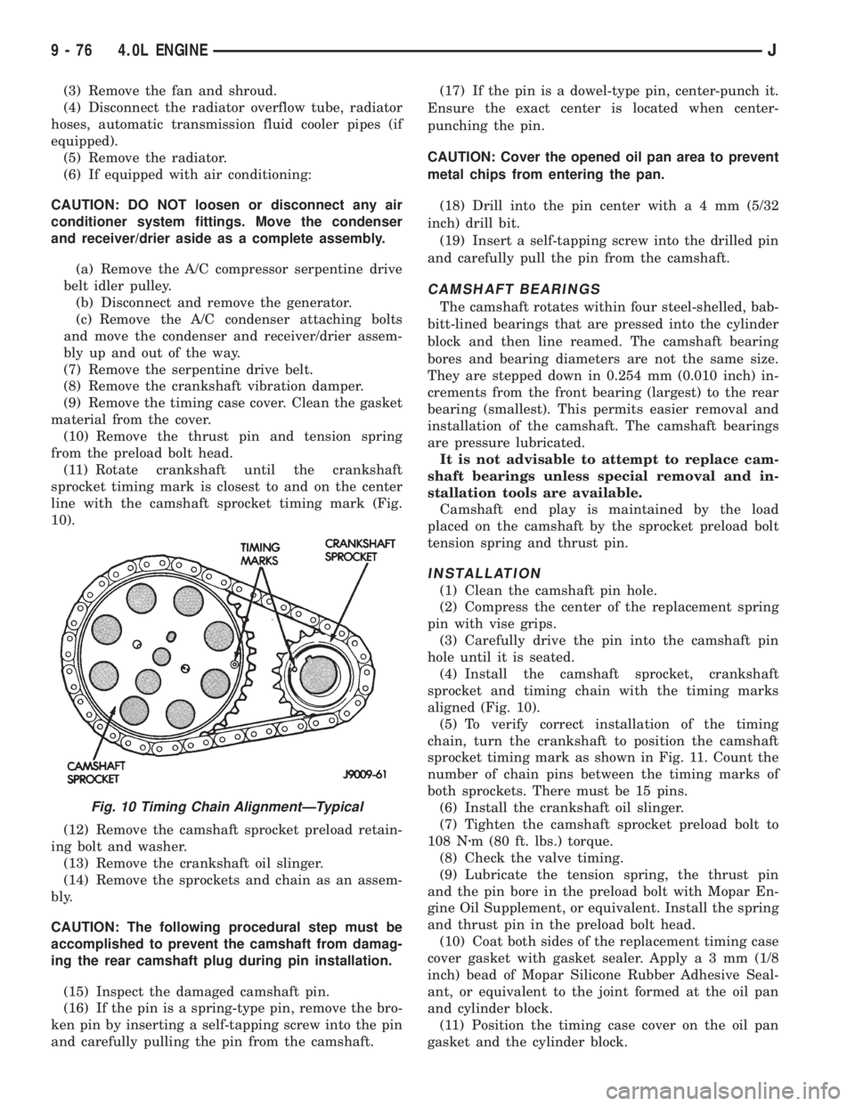
(11) Rotate crankshaft until the crankshaft
sprocket timing mark is closest to and on the center
line with the camshaft sprocket timing mark (Fig.
10).
(12) Remove the camshaft sprocket preload retain-
ing bolt and washer.
(13) Remove the crankshaft oil slinger.
(14) Remove the sprockets and chain as an assem-
bly.
CAUTION: The following procedural step must be
accomplished to prevent the camshaft from damag-
ing the rear camshaft plug during pin installation.
(15) Inspect the damaged camshaft pin.
(16) If the pin is a spring-type pin, remove the bro-
ken pin by inserting a self-tapping screw into the pin
and carefully pulling the pin from the camshaft.(17) If the pin is a dowel-type pin, center-punch it.
Ensure the exact center is located when center-
punching the pin.
CAUTION: Cover the opened oil pan area to prevent
metal chips from entering the pan.
(18) Drill into the pin center witha4mm(5/32
inch) drill bit.
(19) Insert a self-tapping screw into the drilled pin
and carefully pull the pin from the camshaft.
CAMSHAFT BEARINGS
The camshaft rotates within four steel-shelled, bab-
bitt-lined bearings that are pressed into the cylinder
block and then line reamed. The camshaft bearing
bores and bearing diameters are not the same size.
They are stepped down in 0.254 mm (0.010 inch) in-
crements from the front bearing (largest) to the rear
bearing (smallest). This permits easier removal and
installation of the camshaft. The camshaft bearings
are pressure lubricated.
It is not advisable to attempt to replace cam-
shaft bearings unless special removal and in-
stallation tools are available.
Camshaft end play is maintained by the load
placed on the camshaft by the sprocket preload bolt
tension spring and thrust pin.
INSTALLATION
(1) Clean the camshaft pin hole.
(2) Compress the center of the replacement spring
pin with vise grips.
(3) Carefully drive the pin into the camshaft pin
hole until it is seated.
(4) Install the camshaft sprocket, crankshaft
sprocket and timing chain with the timing marks
aligned (Fig. 10).
(5) To verify correct installation of the timing
chain, turn the crankshaft to position the camshaft
sprocket timing mark as shown in Fig. 11. Count the
number of chain pins between the timing marks of
both sprockets. There must be 15 pins.
(6) Install the crankshaft oil slinger.
(7) Tighten the camshaft sprocket preload bolt to
108 Nzm (80 ft. lbs.) torque.
(8) Check the valve timing.
(9) Lubricate the tension spring, the thrust pin
and the pin bore in the preload bolt with Mopar En-
gine Oil Supplement, or equivalent. Install the spring
and thrust pin in the preload bolt head.
(10) Coat both sides of the replacement timing case
cover gasket with gasket sealer. Applya3mm(1/8
inch) bead of Mopar Silicone Rubber Adhesive Seal-
ant, or equivalent to the joint formed at the oil pan
and cylinder block.
(11) Position the timing case cover on the oil pan
gasket and the cylinder block.
Fig. 10 Timing Chain AlignmentÐTypical
9 - 76 4.0L ENGINEJ
Page 1906 of 2198
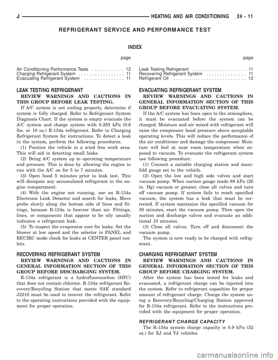
REFRIGERANT SERVICE AND PERFORMANCE TEST
INDEX
page page
Air Conditioning Performance Tests............ 12
Charging Refrigerant System................. 11
Evacuating Refrigerant System............... 11Leak Testing Refrigerant.................... 11
Recovering Refrigerant System............... 11
Refrigerant Oil........................... 12
LEAK TESTING REFRIGERANT
REVIEW WARNINGS AND CAUTIONS IN
THIS GROUP BEFORE LEAK TESTING.
If A/C system is not cooling properly, determine if
system is fully charged. Refer to Refrigerant System
Diagnosis Chart. If the system is empty evacuate the
A/C system and charge system with 0.283 kPa (0.6
lbs. or 10 oz.) R-134a refrigerant. Refer to Charging
Refrigerant System for instructions. To detect a leak
in the system, perform the following procedures.
(1) Position the vehicle in a wind free work area.
This will aid in detecting small leaks.
(2) Bring A/C system up to operating temperature
and pressure. This is done by allowing the engine to
run with the A/C on for 5 to 7 minutes.
(3) Open hood 5 minutes prior to leak test. This
will dissipate any accumulated refrigerant in the en-
gine compartment.
(4) With the engine not running, use an R-134a
Electronic Leak Detector and search for leaks. Move
probe slowly along the bottom side of lines and fit-
tings, because R-134a is heavier than air. Fittings,
lines, or components that appear to be oily usually
indicates a refrigerant leak.
(5) To inspect the evaporator core for leaks. Set the
blower at low speed and the selector in PANEL and
RECIRC mode check for leaks at CENTER panel out-
lets.
RECOVERING REFRIGERANT SYSTEM
REVIEW WARNINGS AND CAUTIONS IN
GENERAL INFORMATION SECTION OF THIS
GROUP BEFORE DISCHARGING SYSTEM.
R-134a refrigerant is a hydrofluorocarbon (HFC)
that does not contain chlorine. R-134a refrigerant Re-
covery/Recycling Station that meets SAE standard
J2210 must be used to recover the refrigerant. Refer
to the operating instructions provided with the equip-
ment for proper operation.
EVACUATING REFRIGERANT SYSTEM
REVIEW WARNINGS AND CAUTIONS IN
GENERAL INFORMATION SECTION OF THIS
GROUP BEFORE EVACUATING SYSTEM.
If the A/C system has been open to the atmosphere,
it must be evacuated before the system can be
charged. Moisture and air mixed with refrigerant will
raise the compressor head pressure above acceptable
operating levels. This will reduce the performance of
the air conditioner and damage the compressor. Mois-
ture will boil at near room temperature when ex-
posed to vacuum. To evacuate the refrigerant system
use following procedure:
(1) Connect a suitable charging station and mani-
fold gauge set to the vehicle.
(2) Open the low and high side valves and start
vacuum pump. When suction gauge reads 88 kPa (26
in. Hg) vacuum or greater, close all valves and turn
off vacuum pump. If system fails to reach specified
vacuum, the system has a leak that must be cor-
rected. If system maintains the specified vacuum for
30 minutes, start the vacuum pump. Then open the
suction and discharge valves and evacuate an addi-
tional 10 minutes.
(3) Close all valves. Turn off and disconnect the
vacuum pump.
The system is now ready to be charged with refrig-
erant.
CHARGING REFRIGERANT SYSTEM
REVIEW WARNINGS AND CAUTIONS IN
GENERAL INFORMATION SECTION OF THIS
GROUP BEFORE CHARGING SYSTEM.
After the system has been tested for leaks and
evacuated, a refrigerant charge can be injected into
the system. Refer to refrigerant capacities for proper
amount of refrigerant charge. Charge the system us-
ing a Recovery/Recycling/Charging Station approved
for R-134a refrigerant. Refer to the instructions pro-
vided with the equipment for proper operation.
REFRIGERANT CHARGE CAPACITY
The R-134a system charge capacity is 0.9 kPa (32
oz.) for XJ and YJ vehicles.
JHEATING AND AIR CONDITIONING 24 - 11
Page 1962 of 2198
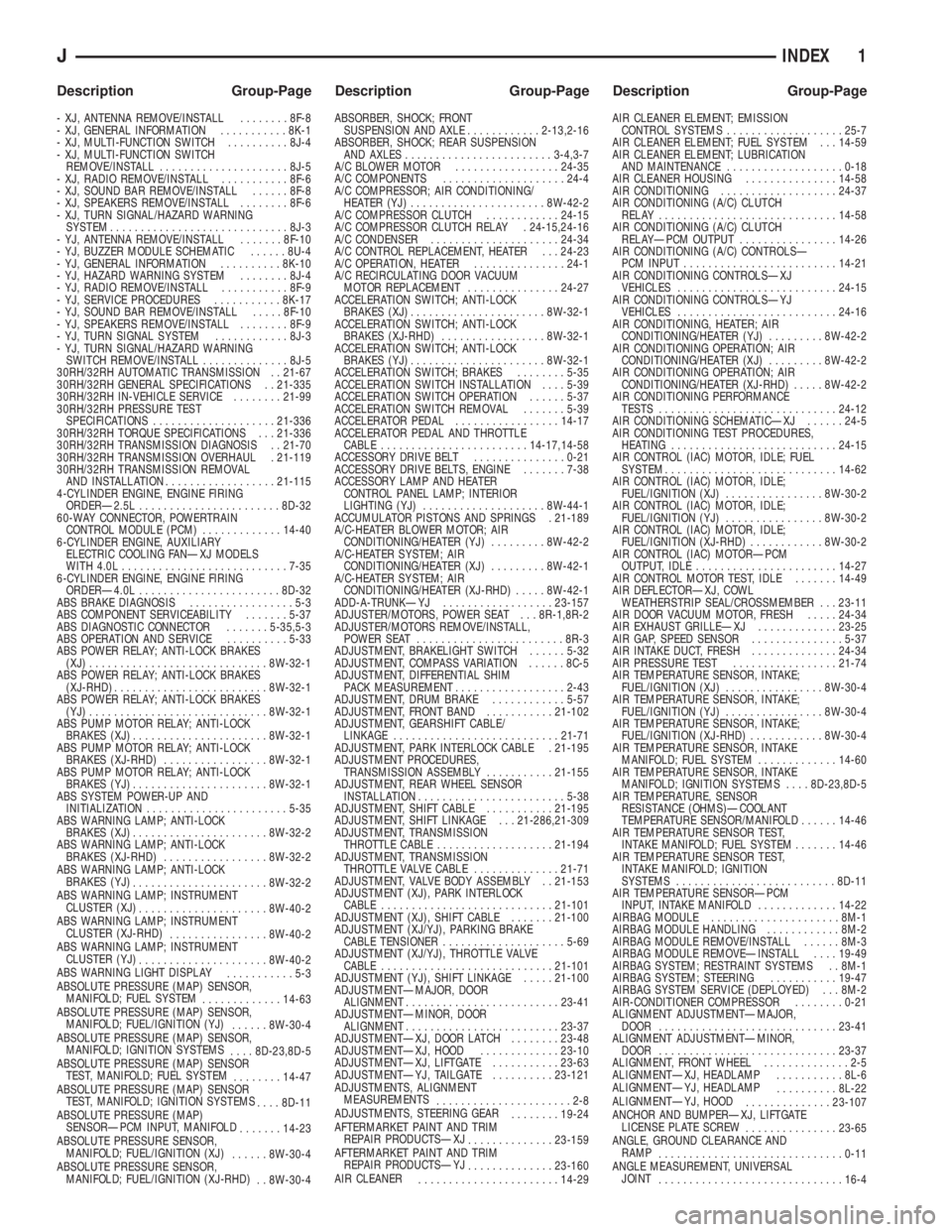
- XJ, ANTENNA REMOVE/INSTALL........8F-8
- XJ, GENERAL INFORMATION...........8K-1
- XJ, MULTI-FUNCTION SWITCH..........8J-4
- XJ, MULTI-FUNCTION SWITCH
REMOVE/INSTALL.....................8J-5
- XJ, RADIO REMOVE/INSTALL...........8F-6
- XJ, SOUND BAR REMOVE/INSTALL......8F-8
- XJ, SPEAKERS REMOVE/INSTALL........8F-6
- XJ, TURN SIGNAL/HAZARD WARNING
SYSTEM.............................8J-3
- YJ, ANTENNA REMOVE/INSTALL.......8F-10
- YJ, BUZZER MODULE SCHEMATIC......8U-4
- YJ, GENERAL INFORMATION..........8K-10
- YJ, HAZARD WARNING SYSTEM........8J-4
- YJ, RADIO REMOVE/INSTALL...........8F-9
- YJ, SERVICE PROCEDURES...........8K-17
- YJ, SOUND BAR REMOVE/INSTALL.....8F-10
- YJ, SPEAKERS REMOVE/INSTALL........8F-9
- YJ, TURN SIGNAL SYSTEM............8J-3
- YJ, TURN SIGNAL/HAZARD WARNING
SWITCH REMOVE/INSTALL..............8J-5
30RH/32RH AUTOMATIC TRANSMISSION . . 21-67
30RH/32RH GENERAL SPECIFICATIONS . . 21-335
30RH/32RH IN-VEHICLE SERVICE........21-99
30RH/32RH PRESSURE TEST
SPECIFICATIONS....................21-336
30RH/32RH TORQUE SPECIFICATIONS . . . 21-336
30RH/32RH TRANSMISSION DIAGNOSIS . . 21-70
30RH/32RH TRANSMISSION OVERHAUL . 21-119
30RH/32RH TRANSMISSION REMOVAL
AND INSTALLATION..................21-115
4-CYLINDER ENGINE, ENGINE FIRING
ORDERÐ2.5L.......................8D-32
60-WAY CONNECTOR, POWERTRAIN
CONTROL MODULE (PCM).............14-40
6-CYLINDER ENGINE, AUXILIARY
ELECTRIC COOLING FANÐXJ MODELS
WITH 4.0L...........................7-35
6-CYLINDER ENGINE, ENGINE FIRING
ORDERÐ4.0L.......................8D-32
ABS BRAKE DIAGNOSIS.................5-3
ABS COMPONENT SERVICEABILITY.......5-37
ABS DIAGNOSTIC CONNECTOR.......5-35,5-3
ABS OPERATION AND SERVICE..........5-33
ABS POWER RELAY; ANTI-LOCK BRAKES
(XJ).............................8W-32-1
ABS POWER RELAY; ANTI-LOCK BRAKES
(XJ-RHD).........................8W-32-1
ABS POWER RELAY; ANTI-LOCK BRAKES
(YJ).............................8W-32-1
ABS PUMP MOTOR RELAY; ANTI-LOCK
BRAKES (XJ)......................8W-32-1
ABS PUMP MOTOR RELAY; ANTI-LOCK
BRAKES (XJ-RHD).................8W-32-1
ABS PUMP MOTOR RELAY; ANTI-LOCK
BRAKES (YJ)......................8W-32-1
ABS SYSTEM POWER-UP AND
INITIALIZATION.......................5-35
ABS WARNING LAMP; ANTI-LOCK
BRAKES (XJ)......................8W-32-2
ABS WARNING LAMP; ANTI-LOCK
BRAKES (XJ-RHD).................8W-32-2
ABS WARNING LAMP; ANTI-LOCK
BRAKES (YJ)
......................8W-32-2
ABS WARNING LAMP; INSTRUMENT
CLUSTER (XJ)
.....................8W-40-2
ABS WARNING LAMP; INSTRUMENT
CLUSTER (XJ-RHD)
................8W-40-2
ABS WARNING LAMP; INSTRUMENT
CLUSTER (YJ)
.....................8W-40-2
ABS WARNING LIGHT DISPLAY
...........5-3
ABSOLUTE PRESSURE (MAP) SENSOR,
MANIFOLD; FUEL SYSTEM
.............14-63
ABSOLUTE PRESSURE (MAP) SENSOR,
MANIFOLD; FUEL/IGNITION (YJ)
......8W-30-4
ABSOLUTE PRESSURE (MAP) SENSOR,
MANIFOLD; IGNITION SYSTEMS
....8D-23,8D-5
ABSOLUTE PRESSURE (MAP) SENSOR
TEST, MANIFOLD; FUEL SYSTEM
........14-47
ABSOLUTE PRESSURE (MAP) SENSOR
TEST, MANIFOLD; IGNITION SYSTEMS
....8D-11
ABSOLUTE PRESSURE (MAP)
SENSORÐPCM INPUT, MANIFOLD
.......14-23
ABSOLUTE PRESSURE SENSOR,
MANIFOLD; FUEL/IGNITION (XJ)
......8W-30-4
ABSOLUTE PRESSURE SENSOR,
MANIFOLD; FUEL/IGNITION (XJ-RHD)
. . 8W-30-4ABSORBER, SHOCK; FRONT
SUSPENSION AND AXLE............2-13,2-16
ABSORBER, SHOCK; REAR SUSPENSION
AND AXLES........................3-4,3-7
A/C BLOWER MOTOR.................24-35
A/C COMPONENTS....................24-4
A/C COMPRESSOR; AIR CONDITIONING/
HEATER (YJ)......................8W-42-2
A/C COMPRESSOR CLUTCH............24-15
A/C COMPRESSOR CLUTCH RELAY . 24-15,24-16
A/C CONDENSER.....................24-34
A/C CONTROL REPLACEMENT, HEATER . . . 24-23
A/C OPERATION, HEATER...............24-1
A/C RECIRCULATING DOOR VACUUM
MOTOR REPLACEMENT...............24-27
ACCELERATION SWITCH; ANTI-LOCK
BRAKES (XJ)......................8W-32-1
ACCELERATION SWITCH; ANTI-LOCK
BRAKES (XJ-RHD).................8W-32-1
ACCELERATION SWITCH; ANTI-LOCK
BRAKES (YJ)......................8W-32-1
ACCELERATION SWITCH; BRAKES........5-35
ACCELERATION SWITCH INSTALLATION....5-39
ACCELERATION SWITCH OPERATION......5-37
ACCELERATION SWITCH REMOVAL.......5-39
ACCELERATOR PEDAL.................14-17
ACCELERATOR PEDAL AND THROTTLE
CABLE........................14-17,14-58
ACCESSORY DRIVE BELT...............0-21
ACCESSORY DRIVE BELTS, ENGINE.......7-38
ACCESSORY LAMP AND HEATER
CONTROL PANEL LAMP; INTERIOR
LIGHTING (YJ)....................8W-44-1
ACCUMULATOR PISTONS AND SPRINGS . 21-189
A/C-HEATER BLOWER MOTOR; AIR
CONDITIONING/HEATER (YJ).........8W-42-2
A/C-HEATER SYSTEM; AIR
CONDITIONING/HEATER (XJ).........8W-42-1
A/C-HEATER SYSTEM; AIR
CONDITIONING/HEATER (XJ-RHD).....8W-42-1
ADD-A-TRUNKÐYJ..................23-157
ADJUSTER/MOTORS, POWER SEAT . . . 8R-1,8R-2
ADJUSTER/MOTORS REMOVE/INSTALL,
POWER SEAT........................8R-3
ADJUSTMENT, BRAKELIGHT SWITCH......5-32
ADJUSTMENT, COMPASS VARIATION......8C-5
ADJUSTMENT, DIFFERENTIAL SHIM
PACK MEASUREMENT..................2-43
ADJUSTMENT, DRUM BRAKE............5-57
ADJUSTMENT, FRONT BAND...........21-102
ADJUSTMENT, GEARSHIFT CABLE/
LINKAGE...........................21-71
ADJUSTMENT, PARK INTERLOCK CABLE . 21-195
ADJUSTMENT PROCEDURES,
TRANSMISSION ASSEMBLY...........21-155
ADJUSTMENT, REAR WHEEL SENSOR
INSTALLATION........................5-38
ADJUSTMENT, SHIFT CABLE...........21-195
ADJUSTMENT, SHIFT LINKAGE . . . 21-286,21-309
ADJUSTMENT, TRANSMISSION
THROTTLE CABLE...................21-194
ADJUSTMENT, TRANSMISSION
THROTTLE VALVE CABLE..............21-71
ADJUSTMENT, VALVE BODY ASSEMBLY . . 21-153
ADJUSTMENT (XJ), PARK INTERLOCK
CABLE............................21-101
ADJUSTMENT (XJ), SHIFT CABLE.......21-100
ADJUSTMENT (XJ/YJ), PARKING BRAKE
CABLE TENSIONER....................5-69
ADJUSTMENT (XJ/YJ), THROTTLE VALVE
CABLE............................21-101
ADJUSTMENT (YJ), SHIFT LINKAGE.....21-100
ADJUSTMENTÐMAJOR, DOOR
ALIGNMENT.........................23-41
ADJUSTMENTÐMINOR, DOOR
ALIGNMENT.........................23-37
ADJUSTMENTÐXJ, DOOR LATCH........23-48
ADJUSTMENTÐXJ, HOOD.............23-10
ADJUSTMENTÐXJ, LIFTGATE...........23-63
ADJUSTMENTÐYJ, TAILGATE..........23-121
ADJUSTMENTS, ALIGNMENT
MEASUREMENTS
......................2-8
ADJUSTMENTS, STEERING GEAR
........19-24
AFTERMARKET PAINT AND TRIM
REPAIR PRODUCTSÐXJ
..............23-159
AFTERMARKET PAINT AND TRIM
REPAIR PRODUCTSÐYJ
..............23-160
AIR CLEANER
.......................14-29AIR CLEANER ELEMENT; EMISSION
CONTROL SYSTEMS...................25-7
AIR CLEANER ELEMENT; FUEL SYSTEM . . . 14-59
AIR CLEANER ELEMENT; LUBRICATION
AND MAINTENANCE...................0-18
AIR CLEANER HOUSING...............14-58
AIR CONDITIONING...................24-37
AIR CONDITIONING (A/C) CLUTCH
RELAY.............................14-58
AIR CONDITIONING (A/C) CLUTCH
RELAYÐPCM OUTPUT................14-26
AIR CONDITIONING (A/C) CONTROLSÐ
PCM INPUT.........................14-21
AIR CONDITIONING CONTROLSÐXJ
VEHICLES..........................24-15
AIR CONDITIONING CONTROLSÐYJ
VEHICLES..........................24-16
AIR CONDITIONING, HEATER; AIR
CONDITIONING/HEATER (YJ).........8W-42-2
AIR CONDITIONING OPERATION; AIR
CONDITIONING/HEATER (XJ).........8W-42-2
AIR CONDITIONING OPERATION; AIR
CONDITIONING/HEATER (XJ-RHD).....8W-42-2
AIR CONDITIONING PERFORMANCE
TESTS.............................24-12
AIR CONDITIONING SCHEMATICÐXJ......24-5
AIR CONDITIONING TEST PROCEDURES,
HEATING...........................24-15
AIR CONTROL (IAC) MOTOR, IDLE; FUEL
SYSTEM............................14-62
AIR CONTROL (IAC) MOTOR, IDLE;
FUEL/IGNITION (XJ)................8W-30-2
AIR CONTROL (IAC) MOTOR, IDLE;
FUEL/IGNITION (YJ)................8W-30-2
AIR CONTROL (IAC) MOTOR, IDLE;
FUEL/IGNITION (XJ-RHD)............8W-30-2
AIR CONTROL (IAC) MOTORÐPCM
OUTPUT, IDLE.......................14-27
AIR CONTROL MOTOR TEST, IDLE.......14-49
AIR DEFLECTORÐXJ, COWL
WEATHERSTRIP SEAL/CROSSMEMBER . . . 23-11
AIR DOOR VACUUM MOTOR, FRESH.....24-34
AIR EXHAUST GRILLEÐXJ.............23-25
AIR GAP, SPEED SENSOR...............5-37
AIR INTAKE DUCT, FRESH..............24-34
AIR PRESSURE TEST.................21-74
AIR TEMPERATURE SENSOR, INTAKE;
FUEL/IGNITION (XJ)................8W-30-4
AIR TEMPERATURE SENSOR, INTAKE;
FUEL/IGNITION (YJ)................8W-30-4
AIR TEMPERATURE SENSOR, INTAKE;
FUEL/IGNITION (XJ-RHD)............8W-30-4
AIR TEMPERATURE SENSOR, INTAKE
MANIFOLD; FUEL SYSTEM.............14-60
AIR TEMPERATURE SENSOR, INTAKE
MANIFOLD; IGNITION SYSTEMS....8D-23,8D-5
AIR TEMPERATURE, SENSOR
RESISTANCE (OHMS)ÐCOOLANT
TEMPERATURE SENSOR/MANIFOLD......14-46
AIR TEMPERATURE SENSOR TEST,
INTAKE MANIFOLD; FUEL SYSTEM.......14-46
AIR TEMPERATURE SENSOR TEST,
INTAKE MANIFOLD; IGNITION
SYSTEMS..........................8D-11
AIR TEMPERATURE SENSORÐPCM
INPUT, INTAKE MANIFOLD.............14-22
AIRBAG MODULE.....................8M-1
AIRBAG MODULE HANDLING............8M-2
AIRBAG MODULE REMOVE/INSTALL......8M-3
AIRBAG MODULE REMOVEÐINSTALL....19-49
AIRBAG SYSTEM; RESTRAINT SYSTEMS . . 8M-1
AIRBAG SYSTEM; STEERING...........19-47
AIRBAG SYSTEM SERVICE (DEPLOYED) . . . 8M-2
AIR-CONDITIONER COMPRESSOR........0-21
ALIGNMENT ADJUSTMENTÐMAJOR,
DOOR.............................23-41
ALIGNMENT ADJUSTMENTÐMINOR,
DOOR.............................23-37
ALIGNMENT, FRONT WHEEL..............2-5
ALIGNMENTÐXJ, HEADLAMP...........8L-6
ALIGNMENTÐYJ, HEADLAMP
..........8L-22
ALIGNMENTÐYJ, HOOD
..............23-107
ANCHOR AND BUMPERÐXJ, LIFTGATE
LICENSE PLATE SCREW
...............23-65
ANGLE, GROUND CLEARANCE AND
RAMP
..............................0-11
ANGLE MEASUREMENT, UNIVERSAL
JOINT
..............................16-4
JINDEX 1
Description Group-Page Description Group-Page Description Group-Page
Page 1966 of 2198
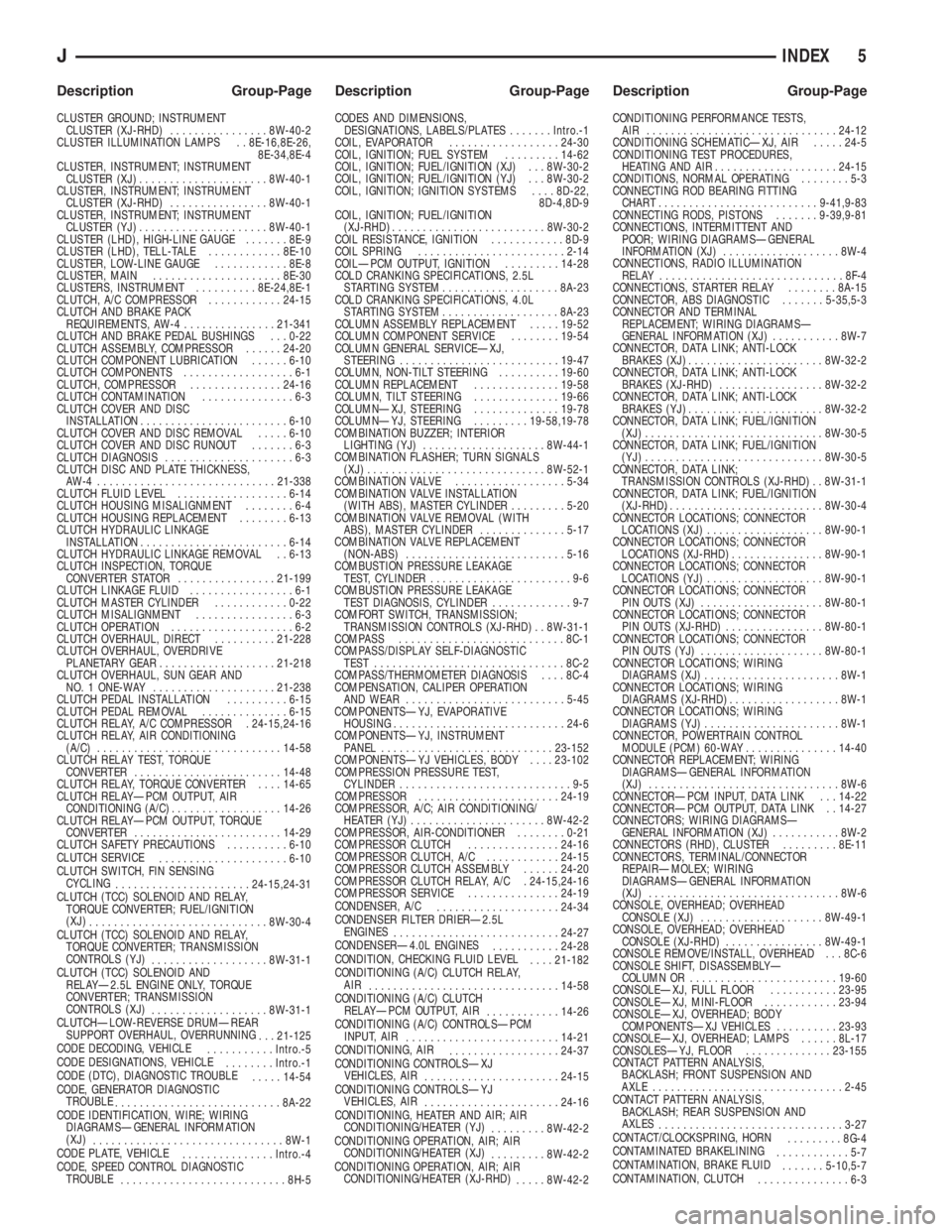
CLUSTER GROUND; INSTRUMENT
CLUSTER (XJ-RHD)................8W-40-2
CLUSTER ILLUMINATION LAMPS . . 8E-16,8E-26,
8E-34,8E-4
CLUSTER, INSTRUMENT; INSTRUMENT
CLUSTER (XJ).....................8W-40-1
CLUSTER, INSTRUMENT; INSTRUMENT
CLUSTER (XJ-RHD)................8W-40-1
CLUSTER, INSTRUMENT; INSTRUMENT
CLUSTER (YJ).....................8W-40-1
CLUSTER (LHD), HIGH-LINE GAUGE.......8E-9
CLUSTER (LHD), TELL-TALE............8E-10
CLUSTER, LOW-LINE GAUGE............8E-8
CLUSTER, MAIN.....................8E-30
CLUSTERS, INSTRUMENT..........8E-24,8E-1
CLUTCH, A/C COMPRESSOR............24-15
CLUTCH AND BRAKE PACK
REQUIREMENTS, AW-4...............21-341
CLUTCH AND BRAKE PEDAL BUSHINGS . . . 0-22
CLUTCH ASSEMBLY, COMPRESSOR......24-20
CLUTCH COMPONENT LUBRICATION......6-10
CLUTCH COMPONENTS..................6-1
CLUTCH, COMPRESSOR...............24-16
CLUTCH CONTAMINATION...............6-3
CLUTCH COVER AND DISC
INSTALLATION........................6-10
CLUTCH COVER AND DISC REMOVAL.....6-10
CLUTCH COVER AND DISC RUNOUT.......6-3
CLUTCH DIAGNOSIS.....................6-3
CLUTCH DISC AND PLATE THICKNESS,
AW-4 .............................21-338
CLUTCH FLUID LEVEL..................6-14
CLUTCH HOUSING MISALIGNMENT........6-4
CLUTCH HOUSING REPLACEMENT........6-13
CLUTCH HYDRAULIC LINKAGE
INSTALLATION........................6-14
CLUTCH HYDRAULIC LINKAGE REMOVAL . . 6-13
CLUTCH INSPECTION, TORQUE
CONVERTER STATOR................21-199
CLUTCH LINKAGE FLUID.................6-1
CLUTCH MASTER CYLINDER............0-22
CLUTCH MISALIGNMENT................6-3
CLUTCH OPERATION....................6-2
CLUTCH OVERHAUL, DIRECT..........21-228
CLUTCH OVERHAUL, OVERDRIVE
PLANETARY GEAR...................21-218
CLUTCH OVERHAUL, SUN GEAR AND
NO. 1 ONE-WAY....................21-238
CLUTCH PEDAL INSTALLATION..........6-15
CLUTCH PEDAL REMOVAL..............6-15
CLUTCH RELAY, A/C COMPRESSOR . 24-15,24-16
CLUTCH RELAY, AIR CONDITIONING
(A/C)..............................14-58
CLUTCH RELAY TEST, TORQUE
CONVERTER........................14-48
CLUTCH RELAY, TORQUE CONVERTER....14-65
CLUTCH RELAYÐPCM OUTPUT, AIR
CONDITIONING (A/C)..................14-26
CLUTCH RELAYÐPCM OUTPUT, TORQUE
CONVERTER........................14-29
CLUTCH SAFETY PRECAUTIONS..........6-10
CLUTCH SERVICE
.....................6-10
CLUTCH SWITCH, FIN SENSING
CYCLING
......................24-15,24-31
CLUTCH (TCC) SOLENOID AND RELAY,
TORQUE CONVERTER; FUEL/IGNITION
(XJ)
.............................8W-30-4
CLUTCH (TCC) SOLENOID AND RELAY,
TORQUE CONVERTER; TRANSMISSION
CONTROLS (YJ)
...................8W-31-1
CLUTCH (TCC) SOLENOID AND
RELAYÐ2.5L ENGINE ONLY, TORQUE
CONVERTER; TRANSMISSION
CONTROLS (XJ)
...................8W-31-1
CLUTCHÐLOW-REVERSE DRUMÐREAR
SUPPORT OVERHAUL, OVERRUNNING
. . . 21-125
CODE DECODING, VEHICLE
...........Intro.-5
CODE DESIGNATIONS, VEHICLE
........Intro.-1
CODE (DTC), DIAGNOSTIC TROUBLE
.....14-54
CODE, GENERATOR DIAGNOSTIC
TROUBLE
...........................8A-22
CODE IDENTIFICATION, WIRE; WIRING
DIAGRAMSÐGENERAL INFORMATION
(XJ)
...............................8W-1
CODE PLATE, VEHICLE
...............Intro.-4
CODE, SPEED CONTROL DIAGNOSTIC
TROUBLE
...........................8H-5CODES AND DIMENSIONS,
DESIGNATIONS, LABELS/PLATES.......Intro.-1
COIL, EVAPORATOR..................24-30
COIL, IGNITION; FUEL SYSTEM.........14-62
COIL, IGNITION; FUEL/IGNITION (XJ) . . . 8W-30-2
COIL, IGNITION; FUEL/IGNITION (YJ) . . . 8W-30-2
COIL, IGNITION; IGNITION SYSTEMS....8D-22,
8D-4,8D-9
COIL, IGNITION; FUEL/IGNITION
(XJ-RHD).........................8W-30-2
COIL RESISTANCE, IGNITION............8D-9
COIL SPRING........................2-14
COILÐPCM OUTPUT, IGNITION.........14-28
COLD CRANKING SPECIFICATIONS, 2.5L
STARTING SYSTEM...................8A-23
COLD CRANKING SPECIFICATIONS, 4.0L
STARTING SYSTEM...................8A-23
COLUMN ASSEMBLY REPLACEMENT.....19-52
COLUMN COMPONENT SERVICE........19-54
COLUMN GENERAL SERVICEÐXJ,
STEERING..........................19-47
COLUMN, NON-TILT STEERING..........19-60
COLUMN REPLACEMENT..............19-58
COLUMN, TILT STEERING..............19-66
COLUMNÐXJ, STEERING..............19-78
COLUMNÐYJ, STEERING.........19-58,19-78
COMBINATION BUZZER; INTERIOR
LIGHTING (YJ)....................8W-44-1
COMBINATION FLASHER; TURN SIGNALS
(XJ).............................8W-52-1
COMBINATION VALVE..................5-34
COMBINATION VALVE INSTALLATION
(WITH ABS), MASTER CYLINDER.........5-20
COMBINATION VALVE REMOVAL (WITH
ABS), MASTER CYLINDER..............5-17
COMBINATION VALVE REPLACEMENT
(NON-ABS)..........................5-16
COMBUSTION PRESSURE LEAKAGE
TEST, CYLINDER.......................9-6
COMBUSTION PRESSURE LEAKAGE
TEST DIAGNOSIS, CYLINDER.............9-7
COMFORT SWITCH, TRANSMISSION;
TRANSMISSION CONTROLS (XJ-RHD) . . 8W-31-1
COMPASS...........................8C-1
COMPASS/DISPLAY SELF-DIAGNOSTIC
TEST...............................8C-2
COMPASS/THERMOMETER DIAGNOSIS....8C-4
COMPENSATION, CALIPER OPERATION
AND WEAR..........................5-45
COMPONENTSÐYJ, EVAPORATIVE
HOUSING............................24-6
COMPONENTSÐYJ, INSTRUMENT
PANEL............................23-152
COMPONENTSÐYJ VEHICLES, BODY....23-102
COMPRESSION PRESSURE TEST,
CYLINDER............................9-5
COMPRESSOR.......................24-19
COMPRESSOR, A/C; AIR CONDITIONING/
HEATER (YJ)......................8W-42-2
COMPRESSOR, AIR-CONDITIONER........0-21
COMPRESSOR CLUTCH...............24-16
COMPRESSOR CLUTCH, A/C............24-15
COMPRESSOR CLUTCH ASSEMBLY......24-20
COMPRESSOR CLUTCH RELAY, A/C . 24-15,24-16
COMPRESSOR SERVICE...............24-19
CONDENSER, A/C
....................24-34
CONDENSER FILTER DRIERÐ2.5L
ENGINES
...........................24-27
CONDENSERÐ4.0L ENGINES
...........24-28
CONDITION, CHECKING FLUID LEVEL
....21-182
CONDITIONING (A/C) CLUTCH RELAY,
AIR
...............................14-58
CONDITIONING (A/C) CLUTCH
RELAYÐPCM OUTPUT, AIR
............14-26
CONDITIONING (A/C) CONTROLSÐPCM
INPUT, AIR
.........................14-21
CONDITIONING, AIR
..................24-37
CONDITIONING CONTROLSÐXJ
VEHICLES, AIR
......................24-15
CONDITIONING CONTROLSÐYJ
VEHICLES, AIR
......................24-16
CONDITIONING, HEATER AND AIR; AIR
CONDITIONING/HEATER (YJ)
.........8W-42-2
CONDITIONING OPERATION, AIR; AIR
CONDITIONING/HEATER (XJ)
.........8W-42-2
CONDITIONING OPERATION, AIR; AIR
CONDITIONING/HEATER (XJ-RHD)
.....8W-42-2CONDITIONING PERFORMANCE TESTS,
AIR ...............................24-12
CONDITIONING SCHEMATICÐXJ, AIR.....24-5
CONDITIONING TEST PROCEDURES,
HEATING AND AIR....................24-15
CONDITIONS, NORMAL OPERATING........5-3
CONNECTING ROD BEARING FITTING
CHART..........................9-41,9-83
CONNECTING RODS, PISTONS.......9-39,9-81
CONNECTIONS, INTERMITTENT AND
POOR; WIRING DIAGRAMSÐGENERAL
INFORMATION (XJ)...................8W-4
CONNECTIONS, RADIO ILLUMINATION
RELAY..............................8F-4
CONNECTIONS, STARTER RELAY........8A-15
CONNECTOR, ABS DIAGNOSTIC.......5-35,5-3
CONNECTOR AND TERMINAL
REPLACEMENT; WIRING DIAGRAMSÐ
GENERAL INFORMATION (XJ)...........8W-7
CONNECTOR, DATA LINK; ANTI-LOCK
BRAKES (XJ)......................8W-32-2
CONNECTOR, DATA LINK; ANTI-LOCK
BRAKES (XJ-RHD).................8W-32-2
CONNECTOR, DATA LINK; ANTI-LOCK
BRAKES (YJ)......................8W-32-2
CONNECTOR, DATA LINK; FUEL/IGNITION
(XJ).............................8W-30-5
CONNECTOR, DATA LINK; FUEL/IGNITION
(YJ).............................8W-30-5
CONNECTOR, DATA LINK;
TRANSMISSION CONTROLS (XJ-RHD) . . 8W-31-1
CONNECTOR, DATA LINK; FUEL/IGNITION
(XJ-RHD)..........................8W-30-4
CONNECTOR LOCATIONS; CONNECTOR
LOCATIONS (XJ)...................8W-90-1
CONNECTOR LOCATIONS; CONNECTOR
LOCATIONS (XJ-RHD)...............8W-90-1
CONNECTOR LOCATIONS; CONNECTOR
LOCATIONS (YJ)...................8W-90-1
CONNECTOR LOCATIONS; CONNECTOR
PIN OUTS (XJ)....................8W-80-1
CONNECTOR LOCATIONS; CONNECTOR
PIN OUTS (XJ-RHD)................8W-80-1
CONNECTOR LOCATIONS; CONNECTOR
PIN OUTS (YJ)....................8W-80-1
CONNECTOR LOCATIONS; WIRING
DIAGRAMS (XJ)......................8W-1
CONNECTOR LOCATIONS; WIRING
DIAGRAMS (XJ-RHD)..................8W-1
CONNECTOR LOCATIONS; WIRING
DIAGRAMS (YJ)......................8W-1
CONNECTOR, POWERTRAIN CONTROL
MODULE (PCM) 60-WAY...............14-40
CONNECTOR REPLACEMENT; WIRING
DIAGRAMSÐGENERAL INFORMATION
(XJ)...............................8W-6
CONNECTORÐPCM INPUT, DATA LINK . . . 14-22
CONNECTORÐPCM OUTPUT, DATA LINK . . 14-27
CONNECTORS; WIRING DIAGRAMSÐ
GENERAL INFORMATION (XJ)...........8W-2
CONNECTORS (RHD), CLUSTER.........8E-11
CONNECTORS, TERMINAL/CONNECTOR
REPAIRÐMOLEX; WIRING
DIAGRAMSÐGENERAL INFORMATION
(XJ)...............................8W-6
CONSOLE, OVERHEAD; OVERHEAD
CONSOLE (XJ)....................8W-49-1
CONSOLE, OVERHEAD; OVERHEAD
CONSOLE (XJ-RHD)................8W-49-1
CONSOLE REMOVE/INSTALL, OVERHEAD . . . 8C-6
CONSOLE SHIFT, DISASSEMBLYÐ
COLUMN OR........................19-60
CONSOLEÐXJ, FULL FLOOR...........23-95
CONSOLEÐXJ, MINI-FLOOR............23-94
CONSOLEÐXJ, OVERHEAD; BODY
COMPONENTSÐXJ VEHICLES..........23-93
CONSOLEÐXJ, OVERHEAD; LAMPS......8L-17
CONSOLESÐYJ, FLOOR..............23-155
CONTACT PATTERN ANALYSIS,
BACKLASH; FRONT SUSPENSION AND
AXLE...............................2-45
CONTACT PATTERN ANALYSIS,
BACKLASH; REAR SUSPENSION AND
AXLES
..............................3-27
CONTACT/CLOCKSPRING, HORN
.........8G-4
CONTAMINATED BRAKELINING
............5-7
CONTAMINATION, BRAKE FLUID
.......5-10,5-7
CONTAMINATION, CLUTCH
...............6-3
JINDEX 5
Description Group-Page Description Group-Page Description Group-Page