1995 JEEP CHEROKEE wiring
[x] Cancel search: wiringPage 1080 of 2198
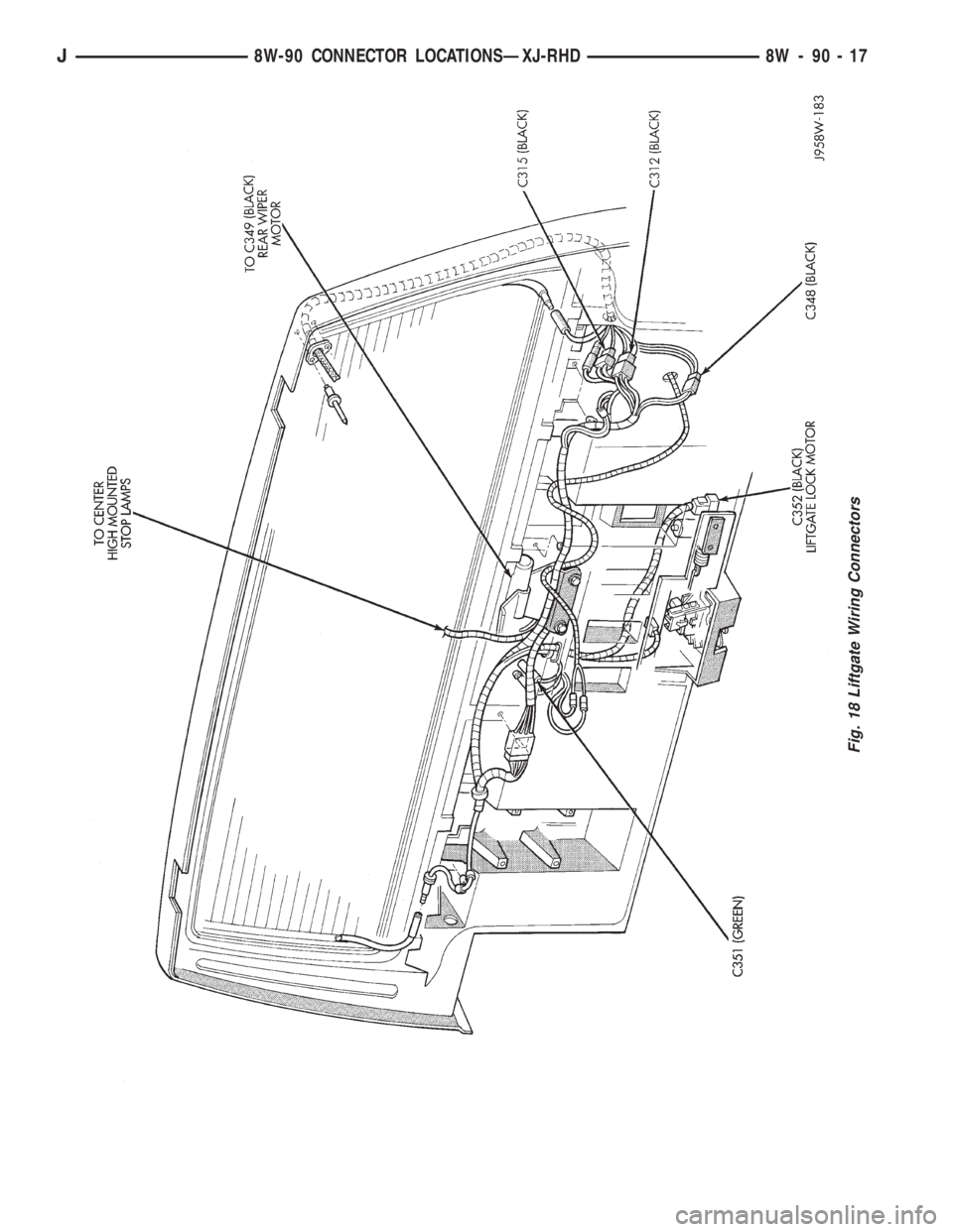
Fig. 18 Liftgate Wiring Connectors
J8W-90 CONNECTOR LOCATIONSÐXJ-RHD 8W - 90 - 17
Page 1081 of 2198
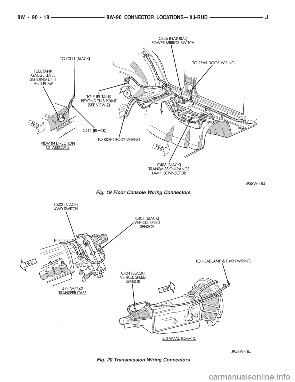
Fig. 19 Floor Console Wiring Connectors
Fig. 20 Transmission Wiring Connectors
8W - 90 - 18 8W-90 CONNECTOR LOCATIONSÐXJ-RHDJ
Page 1082 of 2198
SPLICE LOCATIONS
GENERAL INFORMATION
This section provides illustrations identifying the
general location of the splices in this vehicle. A spliceindex is provided. Use the wiring diagrams in each
section for splice number identification. Refer to the
index for the proper splice number.
SPLICE LOCATIONS
Splice
NumberLocations Fig.
S101......InT/OforHorn and Radiator Fan Motor....2
S102......Before T/O for A/C Low Pressure Switch....2
S103......Before T/O for A/C Low Pressure Switch....2
S104......After T/O for A/C Low Pressure Switch.....2
S105......After T/O for A/C Low Pressure Switch.....2
S106......Before T/O for MAP Sensor............2
S107......Before T/O for MAP Sensor............2
S108......Before T/O for Injector No. 4...........4
S109......Before T/O for Injector No. 6...........4
S110......After T/O for MAP Sensor.............2
S111......After T/O for MAP Sensor.............2
S112......After T/O for Injectors................3
S113......After T/O for Injectors................3
S114......Before T/O for Brake Warning Switch......3
S115......Before T/O for Brake Warning Switch......3
S116......Before T/O for Brake Warning Switch......3
S117......InT/OforDash Connectors, Before Grommet .3
S118......InT/OforDash Connectors, Before Grommet .3
S119......InT/OforABSControl Module, After Grommet .5
S120......After T/O for Underhood Lamp..........3
S121......Before T/O for PDC..................3
S122......Before T/O for PDC..................3
S123......Before T/O for Ambient Air Temperature
Sensor........................3
S124......Near T/O for Ignition Coil and Generator....4
S125......After T/O for Left Fog Lamp............1
S126......Near Clip for Middle of Gille Opening......1
S127......Before T/O for Right Fog Lamp..........1
S201......Before T/O for Right Door Speaker (With ABS) .6
S201......Before T/O for Right Door Speaker (Without ABS)
...............................6
S202......Before T/O for Right Door Speaker (With ABS) .6
S202......Before T/O for Right Door Speaker
(Without ABS)....................6
S203......After T/O for Right Door Jamb Switch (With
ABS)...........................6
S204......Before T/O for Stop Lamp Switch (With ABS) .6
S205......Before T/O for Stop Lamp Switch (With ABS) .6
S205......Before T/O for Stop Lamp Switch (Without ABS)
...............................6
S206......Before T/O for Stop Lamp Switch (With ABS) .6
S206......After T/O for Heated Rear Window Switch and
Fog Lamp Switch (Without ABS).........6
S207......Before T/O for Headlamp Switch (With ABS) .6
S208......InT/OforHeated Rear Window Switch and Fog
Lamp Switch (With ABS)..............6Splice
NumberLocations Fig.
S208......Before T/O for Headlamp Switch
(Without ABS)....................6
S209......After T/O for Heated Rear Window Switch
and Fog Lamp Switch (With ABS).......6
S209......After T/O for Right Door Jamb Switch
(Without ABS)....................6
S210......After T/O for Heated Rear Window Switch and
Fog Lamp Switch (With ABS)...........6
S210......Before T/O for Headlamp Switch
(Without ABS)....................6
S211......After T/O for Antenna (With ABS)........6
S211......After T/O for A/C-Heater Mode Switch
(Without ABS)....................6
S212......InT/OforRelay Center (With ABS).......6
S212......InT/OforRelay Center (Without ABS).....6
S213......InT/OforRelay Center (With ABS).......6
S214......After T/O for Wiper Switch (With ABS).....6
S214......After T/O for A/C-Heater Mode Switch
(Without ABS)...................6
S215......After T/O for A/C-Heater Blower Motor
Switch (With ABS).................6
S216......After T/O for A/C-Heater Mode Switch
(With ABS)......................6
S216......After T/O for A/C-Heater Blower Motor
Switch (Without ABS)...............6
S217......After T/O for A/C-Heater Mode Switch
(With ABS)......................6
S217......After T/O for A/C-Heater Mode Switch
(Without ABS)....................6
S218......After T/O for A/C-Heater Mode Switch
(With ABS).....................6
S218......InT/OforRelay Center (Without ABS).....6
S219......After T/O for Glove Box (With ABS).......6
S220......After T/O for A/C-Heater Mode Switch
(With ABS)......................6
S220......After T/O for A/C-Heater Mode Switch
(Without ABS)....................6
S221......After T/O for Blower Motor Resistor Block
(With ABS)......................6
S222......Before T/O for Stop Lamp Switch
(Without ABS)....................6
S223......After T/O for Heated Rear Window Switch
and Fog Lamp Switch (Without ABS).....6
S224......After T/O for Glove Box (Without ABS).....6
S301......Bottom of Left Front Door Opening.......9
S302......Bottom of Left Front Door Opening.......9
S303......Bottom of Left Front Door Opening.......9
S304......Bottom of Left Front Door Opening.......9
J8W-95 SPLICE LOCATIONSÐXJ-RHD 8W - 95 - 1
Page 1238 of 2198
The engine will not operate if the PCM does not re-
ceive a crankshaft position sensor input.
ENGINE COOLANT TEMPERATURE SENSORÐPCM
INPUT
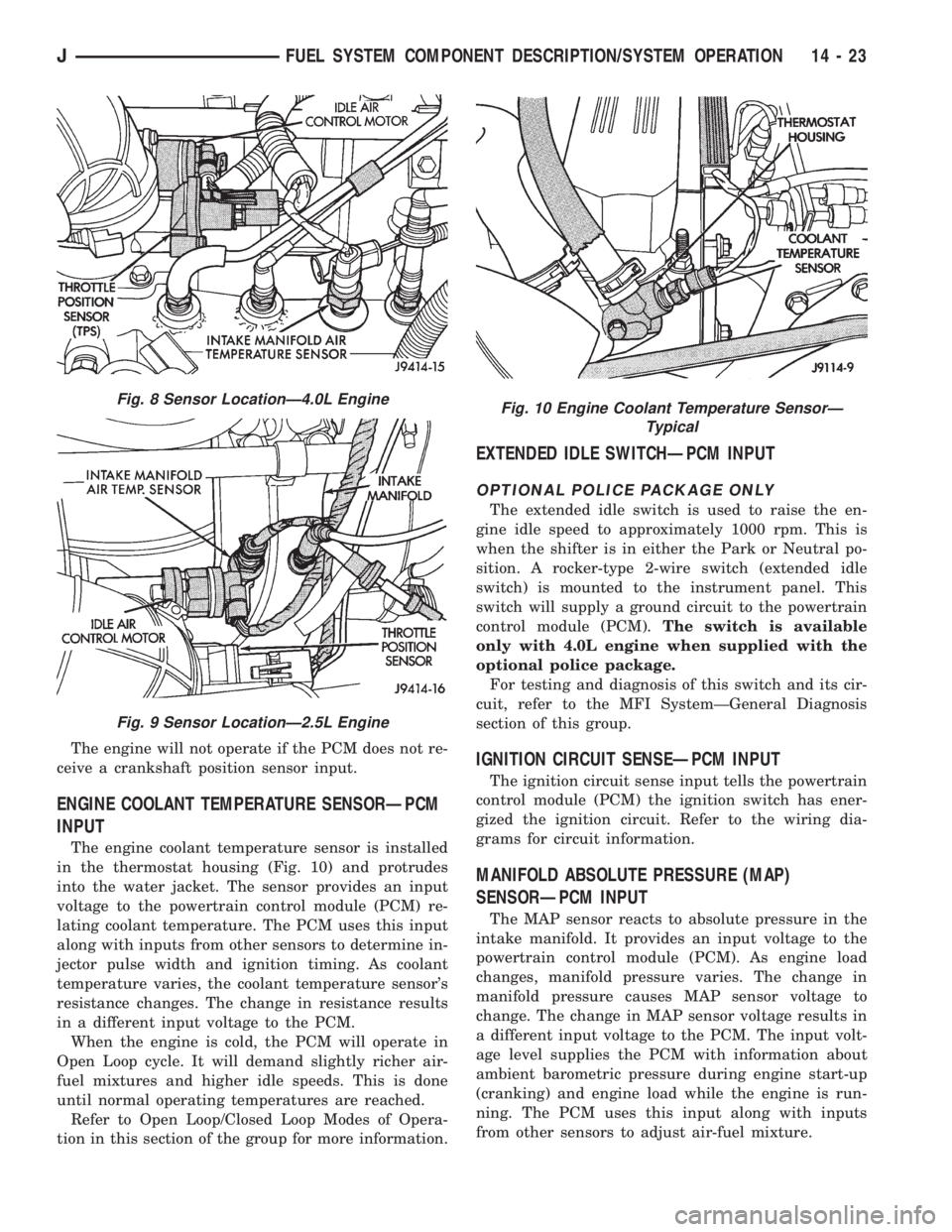
The engine coolant temperature sensor is installed
in the thermostat housing (Fig. 10) and protrudes
into the water jacket. The sensor provides an input
voltage to the powertrain control module (PCM) re-
lating coolant temperature. The PCM uses this input
along with inputs from other sensors to determine in-
jector pulse width and ignition timing. As coolant
temperature varies, the coolant temperature sensor's
resistance changes. The change in resistance results
in a different input voltage to the PCM.
When the engine is cold, the PCM will operate in
Open Loop cycle. It will demand slightly richer air-
fuel mixtures and higher idle speeds. This is done
until normal operating temperatures are reached.
Refer to Open Loop/Closed Loop Modes of Opera-
tion in this section of the group for more information.
EXTENDED IDLE SWITCHÐPCM INPUT
OPTIONAL POLICE PACKAGE ONLY
The extended idle switch is used to raise the en-
gine idle speed to approximately 1000 rpm. This is
when the shifter is in either the Park or Neutral po-
sition. A rocker-type 2-wire switch (extended idle
switch) is mounted to the instrument panel. This
switch will supply a ground circuit to the powertrain
control module (PCM).The switch is available
only with 4.0L engine when supplied with the
optional police package.
For testing and diagnosis of this switch and its cir-
cuit, refer to the MFI SystemÐGeneral Diagnosis
section of this group.
IGNITION CIRCUIT SENSEÐPCM INPUT
The ignition circuit sense input tells the powertrain
control module (PCM) the ignition switch has ener-
gized the ignition circuit. Refer to the wiring dia-
grams for circuit information.
MANIFOLD ABSOLUTE PRESSURE (MAP)
SENSORÐPCM INPUT
The MAP sensor reacts to absolute pressure in the
intake manifold. It provides an input voltage to the
powertrain control module (PCM). As engine load
changes, manifold pressure varies. The change in
manifold pressure causes MAP sensor voltage to
change. The change in MAP sensor voltage results in
a different input voltage to the PCM. The input volt-
age level supplies the PCM with information about
ambient barometric pressure during engine start-up
(cranking) and engine load while the engine is run-
ning. The PCM uses this input along with inputs
from other sensors to adjust air-fuel mixture.
Fig. 8 Sensor LocationÐ4.0L Engine
Fig. 9 Sensor LocationÐ2.5L Engine
Fig. 10 Engine Coolant Temperature SensorÐ
Typical
JFUEL SYSTEM COMPONENT DESCRIPTION/SYSTEM OPERATION 14 - 23
Page 1242 of 2198
DATA LINK CONNECTORÐPCM OUTPUT
Refer to the previous paragraphs on Data Link
ConnectorÐPCM Input for information.
EMR LAMPÐPCM OUTPUT
The EMR (SRI) lamp is not used for the 1995
model year.
FUEL PUMP RELAYÐPCM OUTPUT
The PCM energizes the fuel pump and the oxygen
sensor (O2S) heating element through the fuel pump
relay. Battery voltage is applied to the relay from the
ignition switch. The relay is energized when a
ground is provided by the PCM. Refer to Automatic
Shutdown Relay for additional information.
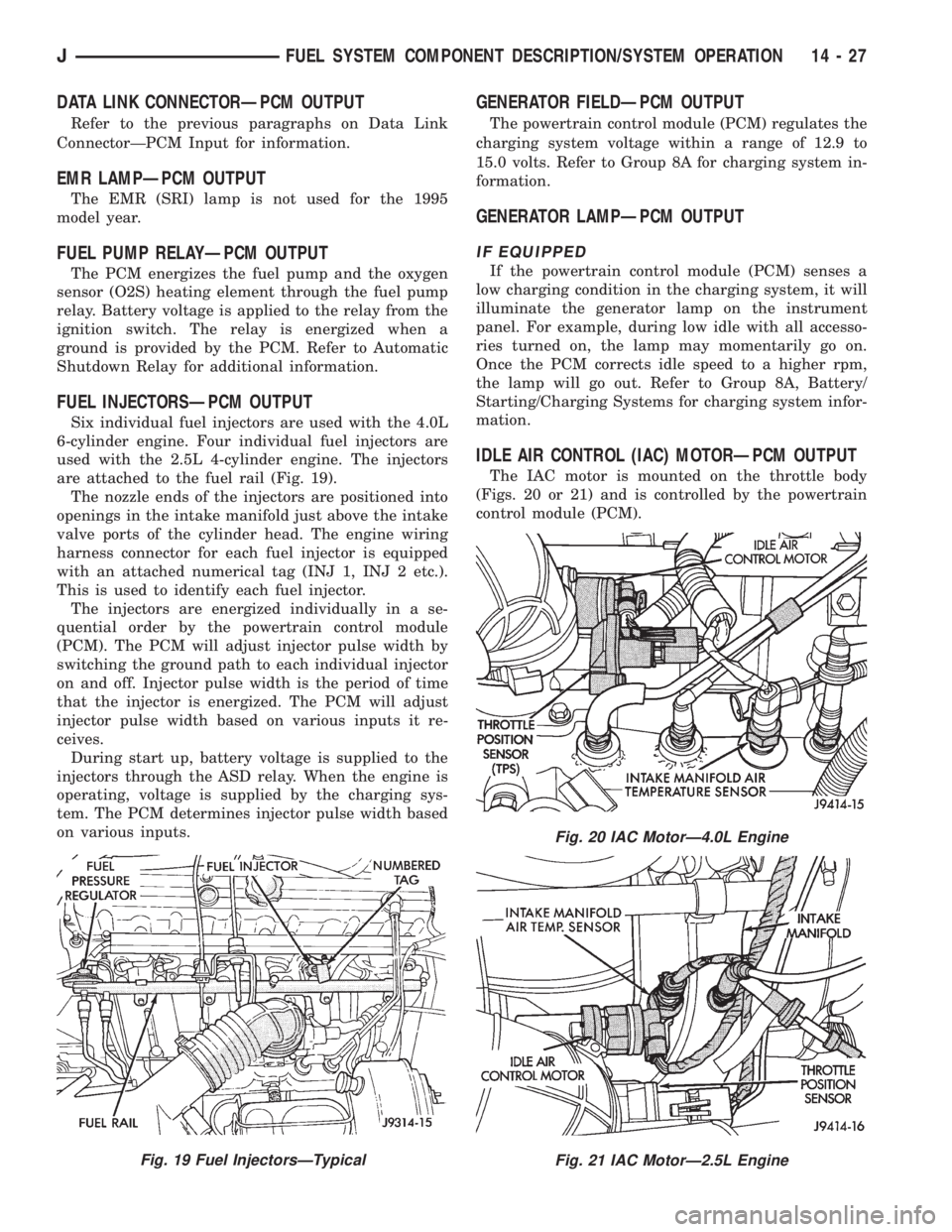
FUEL INJECTORSÐPCM OUTPUT
Six individual fuel injectors are used with the 4.0L
6-cylinder engine. Four individual fuel injectors are
used with the 2.5L 4-cylinder engine. The injectors
are attached to the fuel rail (Fig. 19).
The nozzle ends of the injectors are positioned into
openings in the intake manifold just above the intake
valve ports of the cylinder head. The engine wiring
harness connector for each fuel injector is equipped
with an attached numerical tag (INJ 1, INJ 2 etc.).
This is used to identify each fuel injector.
The injectors are energized individually in a se-
quential order by the powertrain control module
(PCM). The PCM will adjust injector pulse width by
switching the ground path to each individual injector
on and off. Injector pulse width is the period of time
that the injector is energized. The PCM will adjust
injector pulse width based on various inputs it re-
ceives.
During start up, battery voltage is supplied to the
injectors through the ASD relay. When the engine is
operating, voltage is supplied by the charging sys-
tem. The PCM determines injector pulse width based
on various inputs.
GENERATOR FIELDÐPCM OUTPUT
The powertrain control module (PCM) regulates the
charging system voltage within a range of 12.9 to
15.0 volts. Refer to Group 8A for charging system in-
formation.
GENERATOR LAMPÐPCM OUTPUT
IF EQUIPPED
If the powertrain control module (PCM) senses a
low charging condition in the charging system, it will
illuminate the generator lamp on the instrument
panel. For example, during low idle with all accesso-
ries turned on, the lamp may momentarily go on.
Once the PCM corrects idle speed to a higher rpm,
the lamp will go out. Refer to Group 8A, Battery/
Starting/Charging Systems for charging system infor-
mation.
IDLE AIR CONTROL (IAC) MOTORÐPCM OUTPUT
The IAC motor is mounted on the throttle body
(Figs. 20 or 21) and is controlled by the powertrain
control module (PCM).
Fig. 19 Fuel InjectorsÐTypical
Fig. 20 IAC MotorÐ4.0L Engine
Fig. 21 IAC MotorÐ2.5L Engine
JFUEL SYSTEM COMPONENT DESCRIPTION/SYSTEM OPERATION 14 - 27
Page 1251 of 2198
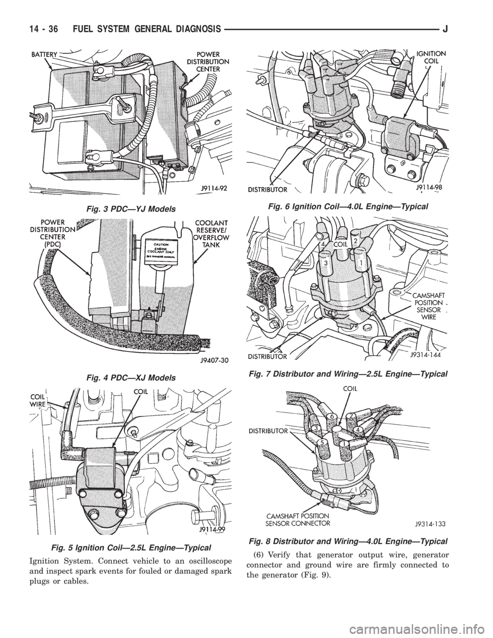
Ignition System. Connect vehicle to an oscilloscope
and inspect spark events for fouled or damaged spark
plugs or cables.(6) Verify that generator output wire, generator
connector and ground wire are firmly connected to
the generator (Fig. 9).
Fig. 3 PDCÐYJ Models
Fig. 4 PDCÐXJ Models
Fig. 5 Ignition CoilÐ2.5L EngineÐTypical
Fig. 6 Ignition CoilÐ4.0L EngineÐTypical
Fig. 7 Distributor and WiringÐ2.5L EngineÐTypical
Fig. 8 Distributor and WiringÐ4.0L EngineÐTypical
14 - 36 FUEL SYSTEM GENERAL DIAGNOSISJ
Page 1252 of 2198
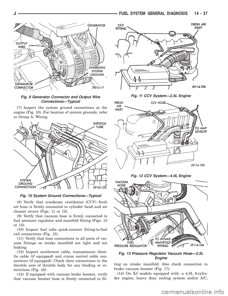
(7) Inspect the system ground connections at the
engine (Fig. 10). For location of system grounds, refer
to Group 8, Wiring.
(8) Verify that crankcase ventilation (CCV) fresh
air hose is firmly connected to cylinder head and air
cleaner covers (Figs. 11 or 12).
(9) Verify that vacuum hose is firmly connected to
fuel pressure regulator and manifold fitting (Figs. 13
or 14).
(10) Inspect fuel tube quick-connect fitting-to-fuel
rail connections (Fig. 15).
(11) Verify that hose connections to all ports of vac-
uum fittings on intake manifold are tight and not
leaking.
(12) Inspect accelerator cable, transmission throt-
tle cable (if equipped) and cruise control cable con-
nections (if equipped). Check their connections to the
throttle arm of throttle body for any binding or re-
strictions (Fig. 16).
(13) If equipped with vacuum brake booster, verify
that vacuum booster hose is firmly connected to fit-ting on intake manifold. Also check connection to
brake vacuum booster (Fig. 17).
(14) On XJ models equipped with: a 4.0L 6-cylin-
der engine, heavy duty cooling system and/or A/C,
Fig. 9 Generator Connector and Output Wire
ConnectionsÐTypical
Fig. 10 System Ground ConnectionsÐTypical
Fig. 11 CCV SystemÐ2.5L Engine
Fig. 12 CCV SystemÐ4.0L Engine
Fig. 13 Pressure Regulator Vacuum HoseÐ2.5L
Engine
JFUEL SYSTEM GENERAL DIAGNOSIS 14 - 37
Page 1254 of 2198
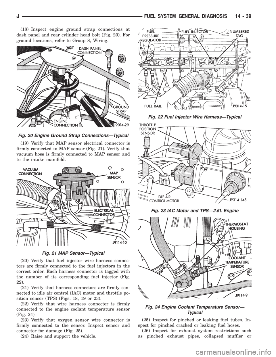
(18) Inspect engine ground strap connections at
dash panel and rear cylinder head bolt (Fig. 20). For
ground locations, refer to Group 8, Wiring.
(19) Verify that MAP sensor electrical connector is
firmly connected to MAP sensor (Fig. 21). Verify that
vacuum hose is firmly connected to MAP sensor and
to the intake manifold.
(20) Verify that fuel injector wire harness connec-
tors are firmly connected to the fuel injectors in the
correct order. Each harness connector is tagged with
the number of its corresponding fuel injector (Fig.
22).
(21) Verify that harness connectors are firmly con-
nected to idle air control (IAC) motor and throttle po-
sition sensor (TPS) (Figs. 18, 19 or 23).
(22) Verify that wire harness connector is firmly
connected to the engine coolant temperature sensor
(Fig. 24).
(23) Verify that oxygen sensor wire connector is
firmly connected to the sensor. Inspect sensor and
connector for damage (Fig. 25).
(24) Raise and support the vehicle.(25) Inspect for pinched or leaking fuel tubes. In-
spect for pinched cracked or leaking fuel hoses.
(26) Inspect for exhaust system restrictions such
as pinched exhaust pipes, collapsed muffler or
Fig. 20 Engine Ground Strap ConnectionsÐTypical
Fig. 21 MAP SensorÐTypical
Fig. 22 Fuel Injector Wire HarnessÐTypical
Fig. 23 IAC Motor and TPSÐ2.5L Engine
Fig. 24 Engine Coolant Temperature SensorÐ
Typical
JFUEL SYSTEM GENERAL DIAGNOSIS 14 - 39