1995 JEEP CHEROKEE oil temperature
[x] Cancel search: oil temperaturePage 16 of 2198

ENGINE MAINTENANCE
INDEX
page page
Accessory Drive Belt....................... 21
Air Cleaner Element....................... 18
Air-Conditioner Compressor.................. 21
Battery................................. 20
Crankcase Ventilation System................ 19
Emission Control System................... 20
Engine Break-In.......................... 15
Engine Cooling System..................... 18
Engine Oil.............................. 15Engine Oil Change and Filter Replacement...... 16
Engine Oil Filter.......................... 17
Engine Supports.......................... 21
Exhaust System.......................... 21
Fuel Filter............................... 19
Fuel Usage StatementÐGas Engines.......... 19
Ignition Cables, Distributor Cap and Rotor....... 20
Rubber and Plastic Component Inspection....... 20
Spark Plugs............................. 20
ENGINE BREAK-IN
CAUTION: Wide open throttle operation in low
gears, before engine break-in period is complete,
can damage engine.
After first starting a new engine, allow it to idle for
15 seconds before shifting into a drive gear. Also:
²Drive the vehicle at varying speeds less than 88
km/h (55 mph) for the first 480 km (300 miles).
²Avoid fast acceleration and sudden stops.
²Do not drive at full-throttle for extended periods of
time.
²Do not drive at constant speeds.
²Do not idle the engine excessively.
A special break-in engine oil is not required. The
original engine oil installed is a high quality, energy
conserving lubricant. Special break-in oils are not
recommended. These oils could interfere with the
normal piston ring seating process.
New engines tend to consume more fuel and oil un-
til after the break-in period has ended.
ENGINE OIL
WARNING: NEW OR USED ENGINE OIL CAN BE IR-
RITATING TO THE SKIN. AVOID PROLONGED OR
REPEATED SKIN CONTACT WITH ENGINE OIL.
CONTAMINANTS IN USED ENGINE OIL, CAUSED BY
INTERNAL COMBUSTION, CAN BE HAZARDOUS TO
YOUR HEALTH. THOROUGHLY WASH EXPOSED
SKIN WITH SOAP AND WATER.
DO NOT WASH SKIN WITH GASOLINE, DIESEL
FUEL, THINNER, OR SOLVENTS, HEALTH PROB-
LEMS CAN RESULT.
DO NOT POLLUTE, DISPOSE OF USED ENGINE
OIL PROPERLY. CONTACT YOUR DEALER OR GOV-
ERNMENT AGENCY FOR LOCATION OF COLLEC-
TION CENTER IN YOUR AREA.
ENGINE OIL SPECIFICATION
CAUTION: Do not use non-detergent or straight
mineral oil when adding or changing crankcase lu-
bricant. Engine failure can result.
API SERVICE GRADE CERTIFIED
Use an engine oil that is API Service Grade Certi-
fied or an oil that conforms to the API Service Grade
SH or SH/CD. MOPAR provides engine oils that con-
form to all of these service grades.
SAE VISCOSITY
An SAE viscosity grade is used to specify the vis-
cosity grade of engine oil. SAE 30 specifies a single
viscosity engine oil. Engine oils also have multiple
viscosities. These are specified with a dual SAE vis-
cosity grade which indicates the cold-to-hot tempera-
ture viscosity range. Select an engine oil that is best
suited to your particular temperature range and vari-
ation (Fig.1).
ENERGY CONSERVING OIL
An Energy Conserving type oil is recommeded for
gasoline engines. They are designated as either EN-
ERGY CONSERVING or ENERGY CONSERVING
II.
Fig. 1 Temperature/Engine Oil Viscosity
JLUBRICATION AND MAINTENANCE 0 - 15
Page 19 of 2198
USED ENGINE OIL DISPOSAL
Care should be exercised when disposing used en-
gine oil after it has been drained from a vehicle en-
gine. Refer to the WARNING listed above.
ENGINE COOLING SYSTEM
WARNINGS AND PRECAUTIONS
WARNING: ANTIFREEZE IS AN ETHYLENE GLYCOL
BASE COOLANT AND IS HARMFUL IF SWAL-
LOWED OR INHALED. IF SWALLOWED, DRINK
TWO GLASSES OF WATER AND INDUCE VOMIT-
ING. IF INHALED, MOVE TO FRESH AIR AREA.
SEEK MEDICAL ATTENTION IMMEDIATELY. DO NOT
STORE IN OPEN OR UNMARKED CONTAINERS.
WASH SKIN AND CLOTHING THOROUGHLY AFTER
COMING IN CONTACT WITH ETHYLENE GLYCOL.
KEEP OUT OF REACH OF CHILDREN.
DISPOSE OF GLYCOL BASE COOLANT PROP-
ERLY, CONTACT YOUR DEALER OR GOVERNMENT
AGENCY FOR LOCATION OF COLLECTION CENTER
IN YOUR AREA.
DO NOT OPEN A COOLING SYSTEM WHEN THE
ENGINE IS AT RUNNING TEMPERATURE, PER-
SONAL INJURY CAN RESULT.
AVOID RADIATOR COOLING FAN WHEN ENGINE
COMPARTMENT RELATED SERVICE IS PER-
FORMED, PERSONAL INJURY CAN RESULT.
CAUTION: Do not use straight antifreeze as engine
coolant, inadequate engine running temperatures
can result.
Do not operate vehicle without proper concentra-
tion of recommended ethylene glycol coolant, high
running temperatures and cooling system corrosion
can result.
The engine cooling system will develop internal
pressure of 97 to 123 kPa (14 to 18 psi) at normal op-
erating temperature. Allow the vehicle approximately
one half hour to cool off before opening the cooling
system. As an indicator of pressure, squeeze the up-
per radiator hose between index finger and thumb. If
it collapses with little effort the system would have
low internal pressure and should be safe to open to
the first safety notch of the radiator cap. Refer to
Group 7, Cooling System.
COOLING SYSTEM INSPECTION
Coolant level should be inspected when other en-
gine compartment service is performed or when cool-
ant leak is suspected. With the engine at normal
operating temperature, observe the coolant level in
thecoolant recovery bottle. The coolant level mustbe at least above the ADD mark and preferably at
the FULL mark. Add coolant to the coolant recovery
bottleonly, if necessary.
Cooling system freeze protection should be tested
at the onset of the winter season or every 12 months.
Service is required if coolant is low, contaminated,
rusty or freeze protection is inadequate. To properly
test cooling system, see Group 7, Cooling System.
The cooling system factory fill is a mixture of 50%
Ethylene Glycol based antifreeze and 50% water. Us-
ing a suitable hydrometer, measure antifreeze con-
centration in the radiator when the engine is cool. If
the cooling system has recently been serviced, allow
coolant to circulate for at least 20 minutes before
taking hydrometer reading. Properly mixed coolant
will protect the cooling system to -37ÉC (-35ÉF). If the
freeze protection is above -28ÉC (-20ÉF), drain enough
coolant from the cooling system to allow room to add
antifreeze to achieve adequate protection. A mix table
on the coolant container indicates the amount of an-
tifreeze required to winterize the cooling system
based on the capacity, see Capacity Chart in General
Information section of this group.
ANTIFREEZE SPECIFICATION
Chrysler Corporation recommends the use of Mo-
par Antifreeze/Coolant or a high quality, ethylene
glycol base antifreeze/coolant, with a silicate inhibi-
tor.
COOLING SYSTEM SERVICE
The cooling system should be drained, flushed and
filled with the proper coolant mixture at the inter-
vals described in the Lubrication and Maintenance
Schedules. Refer to General Information section of
this group. For proper service instructions see Group
7, Cooling System.
AIR CLEANER ELEMENT
The air cleaner element should be serviced at the
intervals described in the Lubrication and Mainte-
nance Schedules sections of this group. Additional in-
formation can be found in Group 14, Fuel System
and Group 25, Emission System. Inspect all air
cleaner hoses or tubes for damage or leaks when
other engine compartment service is performed. Re-
place faulty components.
FILTER ELEMENT SERVICE/REPLACEMENT
CAUTION: The air cleaner cover must be installed
properly for the emissions system and engine con-
troller to function correctly.
Do not immerse paper air filter element in clean-
ing solvents, damage can result.
(1) Remove the air cleaner cover from the body/
housing (Fig. 9).
0 - 18 LUBRICATION AND MAINTENANCEJ
Page 24 of 2198

If the transmission is warm, lube oil could
drip out of the fill hole. This is acceptable but
the lube oil should not gush out of the fill hole.
(2) If not acceptable, raise the lube oil level to the
bottom edge of the transmission fill hole.
Add lube oil in small amounts to raise the
level.
(3) Install the fill-hole plug in the transmission.
Tighten the plug with 37 Nzm (27 ft. lbs.) torque.
LUBE OIL CHANGE
When it becomes necessary to change manual
transmission lube oil, use the following procedure.
(1) Raise and support the vehicle.
(2) Remove the fill-hole plug from the transmis-
sion.
(3) Place a container to collect the lube oil under
the transmission drain-hole plug.
(4) Remove the drain-hole plug and drain the lube
oil from the transmission into the container.
Care should be exercised when disposing
used lube oil after it has been drained from a
transmission.
(5) Install the drain-hole plug in the transmission.
Tighten the plug with 37 Nzm (27 ft. lbs.) torque.
(6) Fill the transmission until the lube oil begins to
drip out of the fill hole.
(7) Install the fill-hole plug in the transmission.
Tighten the plug with 37 Nzm (27 ft. lbs.) torque.
(8) Remove the support and lower the vehicle.
AUTOMATIC TRANSMISSION
The automatic transmission fluid should be
changed and bands adjusted at the intervals de-
scribed in the Maintenance Schedules section of this
Group. The automatic transmission should be in-
spected for fluid leaks and proper fluid level whenother under hood service is performed. Refer to
Group 21, Transmission for proper service proce-
dures.
CAUTION: To minimize fluid contamination, verify
that dipstick is seated in the fill tube after fluid level
reading is taken.
TO INSPECT THE TRANSMISSION FLUID
LEVEL
WARNING: USE EXTREME CAUTION WHEN THE
ENGINE IS OPERATING. DO NOT PUT YOUR
HANDS NEAR THE DRIVE BELT, PULLEYS OR FAN
BLADE. DO NOT STAND IN A DIRECT LINE WITH
THE FAN BLADE.
(1) Be sure transmission fluid is at normal operat-
ing temperature. Normal operating temperature is
reached after approximately 15 miles (25km) of oper-
ation.
(2) Position the vehicle on a level surface. This is
important for an accurate fluid level check.
(3) While sitting in driver seat, apply brakes and
place gear selector in each position, then move the
selector to:
²XJ vehicles-P (Park).
²YJ vehicles-N (Neutral).
(4) Apply parking brake.
(5) Raise hood and wipe off dipstick handle to pre-
vent dirt from entering fill tube. Then remove trans-
mission fluid level indicator (dipstick) and wipe clean
with a wiping cloth.
(6) Install dipstick and verify it is seated in fill
hole or tube.
(7) Remove dipstick, with handle above tip, take
fluid level reading. If the vehicle has been driven for
at least 15 minutes before inspecting fluid level,
transmission can be considered hot and reading
should be in the OK area. If vehicle has run for less
than 15 minutes and more than 60 seconds transmis-
sion can be considered warm and reading should be
above MIN mark. Add fluid only if level is below
MIN mark on dipstick when transmission is warm
(Fig. 4).
CAUTION: Do not overfill automatic transmission,
leakage or damage can result.
AUTOMATIC TRANSMISSION FLUID
SPECIFICATION
When it becomes necessary to add fluid or when
the ATF is replaced, use:
²MOPAR Dexron IIE/Mercon ATFonlyfor AW-4
automatic transmissions (XJ vehicles).
²MOPAR ATF PLUS type 7176 (YJ vehicles).
Fig. 3 Manual Transmission Fill- & Drain-Hole
PlugsÐTypical
JLUBRICATION AND MAINTENANCE 0 - 23
Page 31 of 2198
FLUID LEVEL
The fluid level indicator (dipstick) is attached to
the reservoir cap (Fig. 6). The fluid level in the res-
ervoir can be determined with the fluid either hot or
cold.
(1) Remove the cap from the reservoir.
(2) Depending on fluid temperature, if the level is
below the FULL HOT mark or the FULL COLD
mark on the dipstick, add power steering fluid.
(3) Install the cap on the reservoir.CAUTION: Do not over fill power steering reservoir
when adding fluid, seal damage and leakage can re-
sult.
MANUAL STEERING GEAR
The manual steering gear should be inspected for
damage at the same time as the engine oil is
changed and the oil filter is replaced. Refer to Group
19, Steering for additional information and service
procedures.
POWER BRAKE SYSTEM
RECOMMENDED MAINTENANCE
The brake fluid level (Fig. 8) should be inspected
when other underhood service is done. With disc-
brakes, the fluid level can be expected to fall as the
brake pads wear. However, a low fluid level can also
be caused by a leak, and repair will then be neces-
sary. Refer to Group 5, Brakes for proper service pro-
cedures.
In addition, the brake system should be operation-
ally tested periodically to ensure that it is function-
ing normally.
FLUID SPECIFICATION
Jeep power brake systems require MOPAR Heavy-
Duty Brake Fluid, or an equivalent product identified
as conforming to FMVSS No. 116, DOT-3 and SAE
J-1703 specifications.
Use brake fluid from properly sealed container
when adding fluid to the reservoir. Never use re-
claimed fluid or fluid that does not conform to the
DOT/SAE Standards.
CAUTION: Use of a brake fluid that has a lower ini-
tial boiling point then specified by FMVSS No. 116,
DOT 3 and SAE J-1703 could result in sudden brake
failure during hard, prolonged braking.
Do not allow petroleum base fluids to contaminate
the brake fluid. Seal damage will result.
BRAKE FLUID LEVEL
STANDARD POWER BRAKE SYSTEM
(1) Clean the cover and the sides of the brake fluid
reservoir.
(2) Detach the bail retainer from the reservoir
cover and remove the cover from the reservoir.
(3) The brake fluid level should be 6 mm (1/4 in)
below the rim of each reservoir well for XJ and YJ
Vehicles (Fig. 7 and 8). If not, add brake fluid as nec-
essary.
(4) Inspect the reservoir cover bail retainer for ten-
sion and the cover for proper fit. The cover should fit
tight and have a good seal.
Fig. 5 Power Steering SystemÐYJ Vehicles
Fig. 6 Power Steering Fluid Reservoir DipstickÐ
Typical
0 - 30 LUBRICATION AND MAINTENANCEJ
Page 57 of 2198

MODEL 30 AXLE AND TUBE AXLE (2WD)
INDEX
page page
Axle Bushing Replacement.................. 34
Axle ShaftÐCardan U-Joint.................. 26
Backlash and Contact Pattern Analysis......... 45
Cleaning/Inspection........................ 37
Differential and Pinion Measurement........... 40
Differential Assembly....................... 38
Differential Disassembly.................... 35
Differential Installation...................... 44
Differential Removal....................... 34
Differential Shim Pack Measurement and
Adjustment............................ 43
Drive Axle Assembly ReplacementÐXJ Vehicles . . 23
Drive Axle Assembly ReplacementÐYJ Vehicles . . 24Final Assembly........................... 46
Hub Bearing and Axle Shaft................. 25
Information.............................. 22
Inner Axle Shaft Oil Seal Replacement......... 35
Lubricant Change......................... 23
Lubricant Specifications..................... 22
Pinion Gear Assembly/Installation............. 42
Pinion Gear Depth Information............... 39
Pinion Removal/Disassembly................. 36
Pinion Seal Replacement................... 25
Steering Knuckle and Ball Studs.............. 32
Vacuum Disconnect AxleÐYJ Vehicles......... 27
INFORMATION
The Model 30 front axles consists of a cast iron dif-
ferential housing with axle shaft tubes extending
from either side. The tubes are pressed into the dif-
ferential housing and welded.
The integral type housing, hypoid gear design has
the centerline of the pinion set above the centerline
of the ring gear.
The axle has a fitting for a vent hose used to re-
lieve internal pressure caused by lubricant vaporiza-
tion and internal expansion.
The axles are equipped with semi-floating axle
shafts, meaning that loads are supported by the hub
bearings. The axle shafts are retained by nuts at the
hub bearings. The hub bearings are bolted to the
steering knuckle at the outboard end of the axle tube
yoke. The hub bearings are serviced as an assembly.
The axles are equipped with ABS brake sensors.
The sensors are attached to the knuckle assemblies
and tone rings are pressed on the axle shaft.Use
care when removing axle shafts as NOT to dam-
age the tone wheel or the sensor.
The stamped steel cover provides a means for in-
spection and servicing the differential.
The Model 30 axle has the assembly part number
and gear ratio listed on a tag. The tag is attached to
the housing cover. Build date identification codes are
stamped on the axle shaft tube cover side.
The differential case is a one-piece design. The dif-
ferential pinion mate shaft is retained with a roll
pin. Differential bearing preload and ring gear back-
lash is adjusted by the use of shims (select thick-
ness). The shims are located between the differential
bearing cones and case. Pinion bearing preload is set
and maintained by the use of collapsible spacer.
COMMAND-TRACÐYJ VEHICLES
The Command-Trac system is a vacuum disconnect
axle. The system has a two-piece axle shaft coupled
together by a shift collar. For two-wheel drive opera-
tion, the vacuum motor and shift fork disengages the
axle shaft splines. For four-wheel drive operation, the
vacuum motor and shift fork engages the axle
splines.
SELEC-TRACÐXJ VEHICLES
The Selec-Trac system is a non-disconnect axle.
Shifting from two-wheel to four-wheel drive is done
at the transfer case.
For XJ vehicles equipped withSelec-Tracand
ABS brake system, refer to Group 5ÐBrakes for ad-
ditional service information.
LUBRICANT SPECIFICATIONS
Multi-purpose, hypoid gear lubricant should be
used for Model 30 axles. The lubricant should have
MIL-L-2105C and API GL 5 quality specifications.
MOPARtHypoid Gear Lubricant conforms to both of
these specifications.
²The factory fill for the Model 30 axle is SAE Ther-
mally Stable 80W-90 gear lubricant.Do not use
heavier weight lubricant, this will cause axle
engagement difficulties.
²The factory installed lubricant quantity for the
NON-DISCONNECT TYPE AXLE is 1.48 L (3.13
pts.).
²The factory installed lubricant quantity for the
VACUUM-DISCONNECT TYPE AXLE is 1.65 L (3.76
pts.).
Refer to Group 0, Lubrication and Maintenance for
additional information regarding temperature range,
viscosity and fluid level.
2 - 22 FRONT SUSPENSION AND AXLEJ
Page 226 of 2198
COOLING SYSTEM
CONTENTS
page page
DIAGNOSIS............................. 4
ENGINE ACCESSORY DRIVE BELTS......... 38
ENGINE BLOCK HEATER.................. 44GENERAL INFORMATION.................. 1
SERVICE PROCEDURES.................. 13
SPECIFICATIONS........................ 45
GENERAL INFORMATION
Throughout this group, references are made to par-
ticular vehicle models by alphabetical designation
(XJ or YJ) or by the particular vehicle nameplate. A
chart showing a breakdown of alphabetical designa-
tions is included in the Introduction section at the
beginning of this manual.
COOLING SYSTEM
The cooling system regulates engine operating tem-
perature. It allows the engine to reach normal oper-
ating temperature as quickly as possible, maintains
normal operating temperature and prevents over-
heating.
The cooling system also provides a means of heat-
ing the passenger compartment and cooling the auto-
matic transmission fluid (if equipped). The cooling
system is pressurized and uses a centrifugal water
pump to circulate coolant throughout the system.
An optional factory installed heavy duty cooling
package is available on most models. The package
consists of a radiator that has an increased number
of cooling fins. XJ models equipped with a 4.0L 6-cyl-inder engine and heavy duty cooling and/or air con-
ditioning also have an auxiliary electric cooling fan.
COOLING SYSTEM COMPONENTS
The cooling system consists of:
²A radiator
²Cooling fan (mechanical and/or electrical)
²Thermal viscous fan drive
²Fan shroud
²Radiator pressure cap
²Thermostat
²Coolant reserve/overflow system
²Transmission oil cooler (if equipped with an auto-
matic transmission)
²Coolant
²Water pump
²Hoses and hose clamps
SYSTEM COOLANT ROUTING
For cooling system flow routings, refer to Figs. 1, 2,
3or4.
JCOOLING SYSTEM 7 - 1
Page 250 of 2198
TANK REMOVAL/INSTALLATION
(1) Remove the tube clamp at the tank and remove
tube.
(2) On YJ models, remove the windshield washer
reservoir and its mounting bracket.
(3) Remove the tank mounting bolts and remove
tank.
(4) Reverse the preceding steps for installation.
RADIATOR PRESSURE CAP
All radiators are equipped with a pressure cap.
This cap releases pressure at some point within a
range of 83-110 kPa (12-16 psi). The pressure relief
point (in pounds) is engraved on top of the cap (Fig.
25).
The cooling system will operate at pressures
slightly above atmospheric pressure. This results in a
higher coolant boiling point allowing increased radi-
ator cooling capacity. The cap (Fig. 25) contains a
spring-loaded pressure relief valve. This valve opens
when system pressure reaches the release range of
83-110 kPa (12-16 psi).
A vent valve in the center of the cap allows a small
coolant flow through the cap when coolant is below
boiling temperature. The valve is completely closed
when boiling point is reached. As coolant cools, it
contracts and creates a vacuum in the cooling sys-
tem. This causes the vacuum valve to open and cool-
ant in reserve/overflow tank to be drawn through
connecting hose into radiator. If the vacuum valve is
stuck shut, radiator hoses will collapse on cool-down.A rubber gasket seals the radiator filler neck. This
is done to maintain vacuum during coolant cool-down
and to prevent leakage when system is under pres-
sure.RADIATOR CAP-TO-FILLER NECK SEALÐ
PRESSURE RELIEF CHECK
With radiator cap installed on filler neck, remove
coolant reserve/ overflow tank hose from nipple on
filler neck. Connect a hand operated vacuum pump
to nipple. Operate pump until a reading of 47-to-61
kPa (14-to-18 in. Hg) appears on gauge. If the read-
ing stays steady, or drops slightly and then remains
steady, the pressure valve seal is good. Replace radi-
ator cap if reading does not hold.
WARNING: THE WARNING WORDS -DO NOT OPEN
HOT- ON THE RADIATOR PRESSURE CAP (FIG. 25)
ARE A SAFETY PRECAUTION. WHEN HOT, PRES-
SURE BUILDS UP IN COOLING SYSTEM. TO PRE-
VENT SCALDING OR INJURY, THE RADIATOR CAP
SHOULD NOT BE REMOVED WHILE THE SYSTEM
IS HOT AND/OR UNDER PRESSURE.
There is no need to remove the radiator capex-
ceptfor the following purposes:
(1) To check and adjust antifreeze freeze point.
(2) To refill system with new antifreeze.
(3) For conducting service procedures.
Fig. 24 Reserve/Overflow TankÐXJ ModelsÐWith
Right Hand Drive
Fig. 25 Radiator Pressure Cap
JCOOLING SYSTEM SERVICE PROCEDURES 7 - 25
Page 259 of 2198
VISCOUS FAN DRIVE
DESCRIPTION AND OPERATION
Also refer to the previous section on Cooling Sys-
tem Fans.
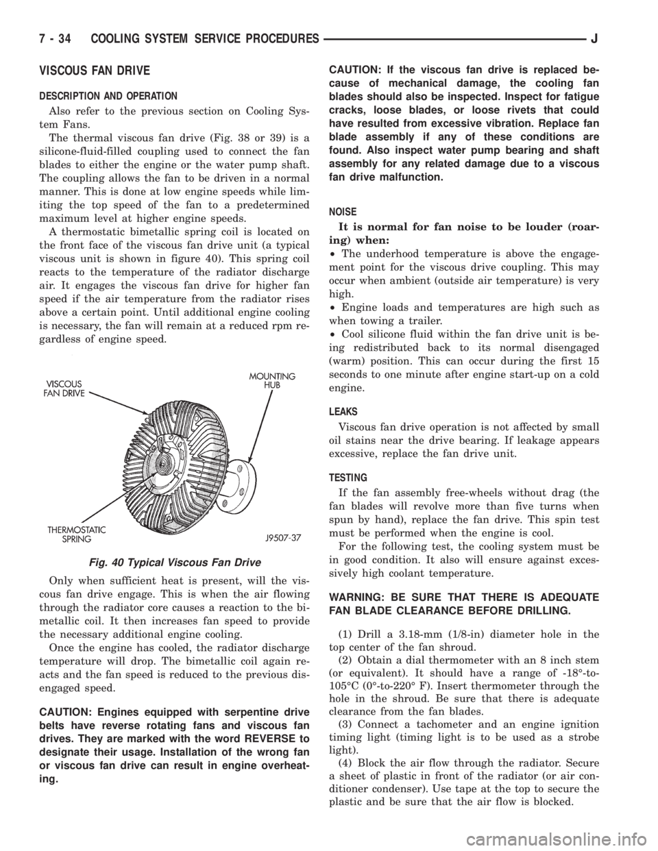
The thermal viscous fan drive (Fig. 38 or 39) is a
silicone-fluid-filled coupling used to connect the fan
blades to either the engine or the water pump shaft.
The coupling allows the fan to be driven in a normal
manner. This is done at low engine speeds while lim-
iting the top speed of the fan to a predetermined
maximum level at higher engine speeds.
A thermostatic bimetallic spring coil is located on
the front face of the viscous fan drive unit (a typical
viscous unit is shown in figure 40). This spring coil
reacts to the temperature of the radiator discharge
air. It engages the viscous fan drive for higher fan
speed if the air temperature from the radiator rises
above a certain point. Until additional engine cooling
is necessary, the fan will remain at a reduced rpm re-
gardless of engine speed.
Only when sufficient heat is present, will the vis-
cous fan drive engage. This is when the air flowing
through the radiator core causes a reaction to the bi-
metallic coil. It then increases fan speed to provide
the necessary additional engine cooling.
Once the engine has cooled, the radiator discharge
temperature will drop. The bimetallic coil again re-
acts and the fan speed is reduced to the previous dis-
engaged speed.
CAUTION: Engines equipped with serpentine drive
belts have reverse rotating fans and viscous fan
drives. They are marked with the word REVERSE to
designate their usage. Installation of the wrong fan
or viscous fan drive can result in engine overheat-
ing.CAUTION: If the viscous fan drive is replaced be-
cause of mechanical damage, the cooling fan
blades should also be inspected. Inspect for fatigue
cracks, loose blades, or loose rivets that could
have resulted from excessive vibration. Replace fan
blade assembly if any of these conditions are
found. Also inspect water pump bearing and shaft
assembly for any related damage due to a viscous
fan drive malfunction.
NOISE
It is normal for fan noise to be louder (roar-
ing) when:
²The underhood temperature is above the engage-
ment point for the viscous drive coupling. This may
occur when ambient (outside air temperature) is very
high.
²Engine loads and temperatures are high such as
when towing a trailer.
²Cool silicone fluid within the fan drive unit is be-
ing redistributed back to its normal disengaged
(warm) position. This can occur during the first 15
seconds to one minute after engine start-up on a cold
engine.
LEAKS
Viscous fan drive operation is not affected by small
oil stains near the drive bearing. If leakage appears
excessive, replace the fan drive unit.
TESTING
If the fan assembly free-wheels without drag (the
fan blades will revolve more than five turns when
spun by hand), replace the fan drive. This spin test
must be performed when the engine is cool.
For the following test, the cooling system must be
in good condition. It also will ensure against exces-
sively high coolant temperature.
WARNING: BE SURE THAT THERE IS ADEQUATE
FAN BLADE CLEARANCE BEFORE DRILLING.
(1) Drill a 3.18-mm (1/8-in) diameter hole in the
top center of the fan shroud.
(2) Obtain a dial thermometer with an 8 inch stem
(or equivalent). It should have a range of -18É-to-
105ÉC (0É-to-220É F). Insert thermometer through the
hole in the shroud. Be sure that there is adequate
clearance from the fan blades.
(3) Connect a tachometer and an engine ignition
timing light (timing light is to be used as a strobe
light).
(4) Block the air flow through the radiator. Secure
a sheet of plastic in front of the radiator (or air con-
ditioner condenser). Use tape at the top to secure the
plastic and be sure that the air flow is blocked.
Fig. 40 Typical Viscous Fan Drive
7 - 34 COOLING SYSTEM SERVICE PROCEDURESJ