1995 BMW 740il center console
[x] Cancel search: center consolePage 17 of 80

Central Locking
Purpose of the System
The Central Locking System provides locking/
unlocking of the entire vehicle from one central
exterior point. From the driver’s door or the
remote (key-less) entry, a lock/unlock request will
lock/unlock all exterior doors, luggage compart-
ment and the fuel filler flap.
From inside, the vehicle can be locked/ unlocked using a cen-
tral locking button located in the center console. Individual
doors can be unlocked manually by pulling twice on the inte-
rior door handle.
From 2000 MY
- if the vehicle has been double locked, press
the central locking button and pull the interior door handle
twice (alarm will sound when the door opens).
Locking the vehicle from the central switch will “single lock” all
doors, luggage compartment and not lock the fuel filler flap.
The Central Locking System utilizes the GM III and Door Modules to carry out all of the lock-
ing/unlocking features:
• Remote (key-less) entry is standard.
• When locked from the outside, the vehicle will double lock and arm the DWA System. The
ignition must be switched off and the driver’s door must be opened and closed.
• Selective unlocking from the outside of the vehicle. Unlocking from the driver’s door or
remote transmitter will only unlock the driver’s door and disarm the DWA System. A sec-
ond request will unlock the remaining doors and luggage compartment. This feature can
be modified for individual users in Key Memory to open all doors from a single request.
• A single central locking button is installed in the center console that will operate when all
of the doors are closed. Locking the vehicle from the central switch will “single lock” all
doors, luggage compartment and not lock the fuel filler flap. When unlocking, a single
request will unlock the driver’s door only. This feature can be modified for individual users
in Key Memory to open all doors and luggage compartment from a single request.
17
Central Body Electronics ZKE III
12510117.jpg
12510118.eps
Page 18 of 80

• A remote luggage compartment button is installed in the left kick panel (center console
in the E53) to open the luggage compartment from inside the vehicle.
• The EWS is interfaced for double lock monitoring and unlock function. With the presence
of an accepted EWS key in the ignition, the vehicle will be unlocked and disarm DWA.
• The automatic locking feature (> 99 MY) activates the door locks when a road speed
signal of 5 MPH and engine RPM is detected via the K-Bus. The factory default setting
of this feature is off (can be encoded on for individual users with Key Memory function).
• In the event of an accident (ignition on), the GM will be signalled to unlock all doors.
Hardware Features:
• The external lock cylinders are located in the
driver’s door and luggage compartment lid
(E53/E39 Sport Wagon does not have a tail-
gate lock cylinder).
• The driver’s door and luggage compartment
incorporates an overrunning lock cylinder. The
lock cylinder will free wheel or spin If any key
other than the vehicle key or tool, such as a
screw driver, is inserted into the cylinder. The
lock cylinders can be manually locked/un-
locked by turning the key “past” lock/unlock.
• The door lock buttons are mechanically uncoupled from the
lock actuators when locked.
The door lock buttons “mechanically” lock the individual
doors. This provides manual locking in the event of a central
locking malfunction.
• Child safety locks (located in
the rear doors) are actuated
by inserting a key in the slot on
the door latch or by sliding a
lever (dependent on model).
The door can now only be
opened from outside.
18
Central Body Electronics ZKE III
Door
Button
Lock
12520117.eps
12520119.eps
12510121.eps
12520120.eps
Page 54 of 80

Rear Seat Interior/Reading Light Units: In
each C pillar trim panel is an interior/reading light
unit.
These units each contain an interior light that is
controlled with the front interior light and a
mechanically switched reading light on the con-
sumer cut off circuit.
Front Footwell Lights: In each front footwell,
there is also a courtesy light. These lights are
only operated when the GM provides power to
the interior lighting circuit.
On E38 and E53 the doors also contain courtesy
lights at the lower edge of the door panel (1).
Door Warning Lights (E38): The additional
“red” warning lights are installed in the edge of
the doors (2). These lights are illuminated when
the doors are opened.
Illuminated Transmission Shift Indicator
(E38): The E38 uses a microprocessor for dis-
playing the shifter position in the center console.
The processor receives shift position signals
from a console mounted range switch. The
processor illuminates the LED corresponding to
the position of the range selector.
The park position LED will remain “on” after the
ignition is switched off and stay on until the GM
goes into the “sleep” mode.
Soft Lighting Feature: The GM provides progressive voltage (up to 12v) providing the soft
on feature
to the interior lighting circuit when the interior lights are required. The GM grad-
ually reduces the full 12 volt power supply providing soft off
when interior light deactivation
is required.
54
Central Body Electronics ZKE III
Park
Position
LED
Page 66 of 80

Principle of Operation
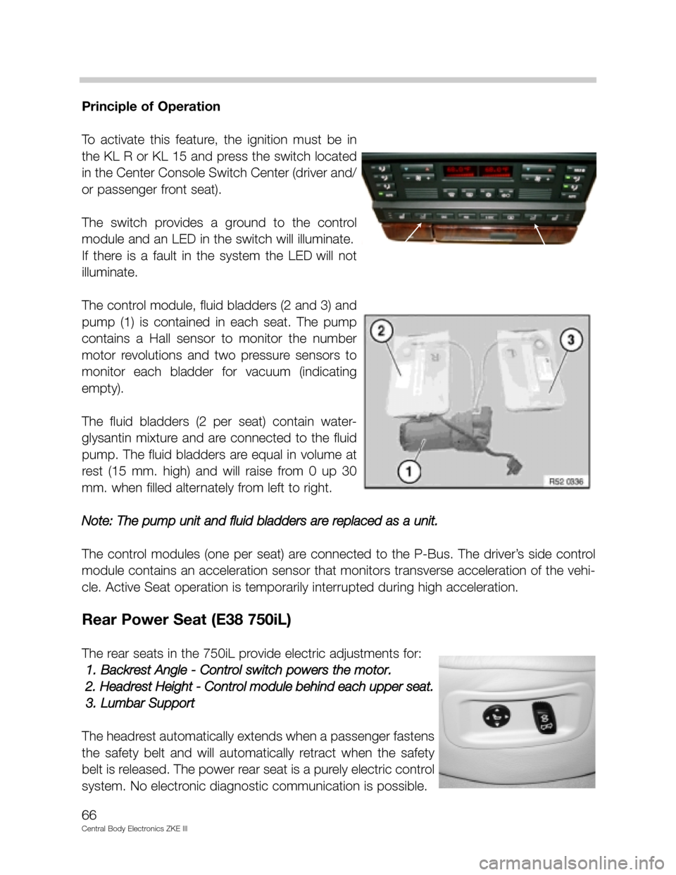
To activate this feature, the ignition must be in
the KL R or KL 15 and press the switch located
in the Center Console Switch Center (driver and/
or passenger front seat).
The switch provides a ground to the control
module and an LED in the switch will illuminate.
If there is a fault in the system the LED will not
illuminate.
The control module, fluid bladders (2 and 3) and
pump (1) is contained in each seat. The pump
contains a Hall sensor to monitor the number
motor revolutions and two pressure sensors to
monitor each bladder for vacuum (indicating
empty).
The fluid bladders (2 per seat) contain water-
glysantin mixture and are connected to the fluid
pump. The fluid bladders are equal in volume at
rest (15 mm. high) and will raise from 0 up 30
mm. when filled alternately from left to right.
Note: The pump unit and fluid bladders are replaced as a unit.
The control modules (one per seat) are connected to the P-Bus. The driver’s side control
module contains an acceleration sensor that monitors transverse acceleration of the vehi-
cle. Active Seat operation is temporarily interrupted during high acceleration.
Rear Power Seat (E38 750iL)
The rear seats in the 750iL provide electric adjustments for:
1. Backrest Angle - Control switch powers the motor.
2. Headrest Height - Control module behind each upper seat.
3. Lumbar Support
The headrest automatically extends when a passenger fastens
the safety belt and will automatically retract when the safety
belt is released. The power rear seat is a purely electric control
system. No electronic diagnostic communication is possible.
66
Central Body Electronics ZKE III
Page 68 of 80

68
Central Body Electronics ZKE III
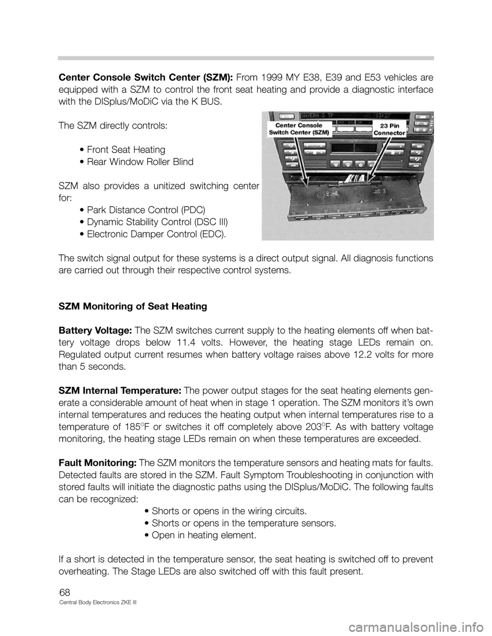
Center Console Switch Center (SZM): From 1999 MY E38, E39 and E53 vehicles are
equipped with a SZM to control the front seat heating and provide a diagnostic interface
with the DISplus/MoDiC via the K BUS.
The SZM directly controls:
• Front Seat Heating
• Rear Window Roller Blind
SZM also provides a unitized switching center
for:
• Park Distance Control (PDC)
• Dynamic Stability Control (DSC III)
• Electronic Damper Control (EDC).
The switch signal output for these systems is a direct output signal. All diagnosis functions
are carried out through their respective control systems.
SZM Monitoring of Seat Heating
Battery Voltage:The SZM switches current supply to the heating elements off when bat-
tery voltage drops below 11.4 volts. However, the heating stage LEDs remain on.
Regulated output current resumes when battery voltage raises above 12.2 volts for more
than 5 seconds.
SZM Internal Temperature: The power output stages for the seat heating elements gen-
erate a considerable amount of heat when in stage 1 operation. The SZM monitors it’s own
internal temperatures and reduces the heating output when internal temperatures rise to a
temperature of 185
OF or switches it off completely above 203OF. As with battery voltage
monitoring, the heating stage LEDs remain on when these temperatures are exceeded.
Fault Monitoring:The SZM monitors the temperature sensors and heating mats for faults.
Detected faults are stored in the SZM. Fault Symptom Troubleshooting in conjunction with
stored faults will initiate the diagnostic paths using the DISplus/MoDiC. The following faults
can be recognized:
• Shorts or opens in the wiring circuits.
• Shorts or opens in the temperature sensors.
• Open in heating element.
If a short is detected in the temperature sensor, the seat heating is switched off to prevent
overheating. The Stage LEDs are also switched off with this fault present.