Page 9 of 65
28-8
Component location Overview of Component
Locations, page Page 24
-5
Notes:
Ignition coils and power output stage are a
common part.
Primary resistance of ignition coils cannot be
measured.
Secondary resistance must first be measured
with the ignition wires connected to the ignition
coils via the spark plug connectors of the
corresponding cylinder (This measurement will
include measurement of the shielded
resistances of the ignition wires).
- Disconnect 5-pin connector from ignition coils.
Check ignition coils (-N-, -N128- and -N158-)
- Pull the ignition wires from the spark plugs.
- In order to perform a resistance measurement, connect multimeter
between both spark plug connectors of the respective ignition circuit to
be checked.
Specification: each 16 to 27 k
Pa
ge 9 of 65 I
gnition s
ystem, checkin
g
11/23/2002 htt
p://127.0.0.1:8080/audi/servlet/Dis
play?action=Goto&t
yp
e=re
pair&id=AUDI.B5.FU05.28.1
Page 10 of 65
- If the specified values are not reached, disconnect ignition wires from
ignition coils and perform a separate resistance measurement at the
ignition wires and at the ignition coils.
Pa
ge 10 of 65 I
gnition s
ystem, checkin
g
11/23/2002 htt
p://127.0.0.1:8080/audi/servlet/Dis
play?action=Goto&t
yp
e=re
pair&id=AUDI.B5.FU05.28.1
Page 11 of 65
28-9
- In order to perform a resistance measurement, connect multimeter
between both ignition wire connectors connectors of the ignition coil to
be checked.
Specification: 8 to 14 k
- In order to perform a resistance measurement, connect multimeter
between both ignition wire connectors connectors of the ignition wire to
be checked.
Specification: 3 to 7 k
- Replace faulty components if the specified values are not reached
again.
Pa
ge 11 of 65 I
gnition s
ystem, checkin
g
11/23/2002 htt
p://127.0.0.1:8080/audi/servlet/Dis
play?action=Goto&t
yp
e=re
pair&id=AUDI.B5.FU05.28.1
Page 12 of 65
28-10
Checking Ground (GND) supply of power
output stage
If LED does not light up:
Electrical Wiring Diagrams, Troubleshooting & Component Locations
binder - Connect VAG1527B voltage tester as follows:Harness connector
Terminal
Measure to
2 B+
LED must light up.
- Check the wire connection for open circuit:
- Repair open circuit if necessary.
Pa
ge 12 of 65 I
gnition s
ystem, checkin
g
11/23/2002 htt
p://127.0.0.1:8080/audi/servlet/Dis
play?action=Goto&t
yp
e=re
pair&id=AUDI.B5.FU05.28.1
Page 13 of 65
28-11
Checking voltage supply to ignition coils
Note:
Voltage is supplied to ignition coils via Fuel
Pump (FP) relay.
Test requirement:
Fuse for ignition coils OK
Electrical Wiring Diagrams, Troubleshooting &
Component Locations binder
If LED does not light up: - Connect VAG1527B voltage tester as follows:Harness connector
Terminal
Measure to
1 Engine Ground (GND)
- Operate starter.
LED must light up.
- Check the wire connection for open circuit:
Pa
ge 13 of 65 I
gnition s
ystem, checkin
g
11/23/2002 htt
p://127.0.0.1:8080/audi/servlet/Dis
play?action=Goto&t
yp
e=re
pair&id=AUDI.B5.FU05.28.1
Page 14 of 65
Electrical Wiring Diagrams, Troubleshooting & Component Locations
binder - Repair open circuit if necessary.
Pa
ge 14 of 65 I
gnition s
ystem, checkin
g
11/23/2002 htt
p://127.0.0.1:8080/audi/servlet/Dis
play?action=Goto&t
yp
e=re
pair&id=AUDI.B5.FU05.28.1
Page 15 of 65
28-12
Checking activation
- Disconnect connectors from all six fuel injectors.
(afterward check DTC memory)
If specified values are not obtained: - Connect VAG1527B voltage tester as follows:Harness connector
Terminal
Measure to
3 Engine Ground (GND)
4 Engine Ground (GND)
5 Engine Ground (GND)
- Operate starter for a few seconds.
LED must blink (brief blink signal).
- Switch ignition off.
- Connect VAG1598/31 test box at wiring harness to ECM, do not
connect ECM Page 24
-17
.
Pa
ge 15 of 65 I
gnition s
ystem, checkin
g
11/23/2002 htt
p://127.0.0.1:8080/audi/servlet/Dis
play?action=Goto&t
yp
e=re
pair&id=AUDI.B5.FU05.28.1
Page 16 of 65
28-13
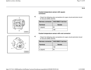
If no malfunctions are found in wires: - Check the following wire connections for open circuit and short circuit
to Ground (GND) and B+: Harness connector
Terminal
VAG1598/31 test box
Socket
3 102
4 103
5 94
- Repair open circuit or short circuit if necessary.
- Replace Engine Control Module (ECM) Page 24
-21
.
Pa
ge 16 of 65 I
gnition s
ystem, checkin
g
11/23/2002 htt
p://127.0.0.1:8080/audi/servlet/Dis
play?action=Goto&t
yp
e=re
pair&id=AUDI.B5.FU05.28.1


 supply of power
output stage
If LED does not light up:
Electrical Wiring Diagrams, Troubleshooting & Component Locations
binder - Connect VAG1527B vo")
 relay.
Test requirement:
Fuse for ignition coils OK")


If specified values are not obtained: - Connect VAG1527B voltage te")
 and B+: Harness connector
Terminal
VAG1598/31 test")