Page 1 of 64

28-1
Ignition system, checking
General notes on ignition system
Always switch off the ignition before connecting
or disconnecting the battery, otherwise the
engine control module may be damaged.
The engine control module is equipped with On
Board Diagnostic (OBD).
For trouble-free operation of the electrical
components a voltage of at least 11.5 V is
necessary.
During some of the tests it is possible that the
control module will detect and record a
malfunction. The DTC memory must therefore
be checked and if necessary erased when all
tests and repair work have been completed.
After completing troubleshooting, repairs or
component tests, it is possible that the engine
will start, run for a short period and then cut out.
If this happens it may be that the immobilizer is
blocking the engine control module. In such
cases the DTC memory must be checked and if
necessary the control module must be adapted.
Pa
ge 1 of 64 I
gnition s
ystem, checkin
g
11/22/2002 htt
p://127.0.0.1:8080/audi/servlet/Dis
play?action=Goto&t
yp
e=re
pair&id=AUDI.B5.FU04.28.1
Page 2 of 64
28-2
Safety precautions
To prevent injuries to persons and/or damage to
the fuel injection and ignition system, the
following must be noted:
WARNING!
Be alert when working on or near the engine.
High ignition secondary voltage can cause
serious personal injury and damage vehicle
components.
DO NOT touch or disconnect ignition wiring
when the engine is running or being turned
at starter speed.
DO NOT operate the starter if fuel injectors
are removed.
Always switch off the ignition before
connecting or disconnecting the battery,
otherwise the engine control module may be
damaged.
The ignition must be switched off before
connecting or disconnecting injection or
ignition system wiring or tester cables.
In order to run the engine at starting speed
Pa
ge 2 of 64 I
gnition s
ystem, checkin
g
11/22/2002 htt
p://127.0.0.1:8080/audi/servlet/Dis
play?action=Goto&t
yp
e=re
pair&id=AUDI.B5.FU04.28.1
Page 3 of 64
without actually starting it (e.g. to test
compression), disconnect the connectors
from the output stages of the ignition coils
and from all the fuel injectors. After
completing the work, check and erase the
DTC memory.
The ignition must always be switched off
when cleaning the engine.
Pa
ge 3 of 64 I
gnition s
ystem, checkin
g
11/22/2002 htt
p://127.0.0.1:8080/audi/servlet/Dis
play?action=Goto&t
yp
e=re
pair&id=AUDI.B5.FU04.28.1
Page 6 of 64
28-5
Ignition coils, checking
Note:
Misfiring is recognized by the On Board
Diagnostic (OBD). This means a non working
cylinder is stored with the cylinder number in the
DTC memory. This has an advantage in case of
a malfunction the trouble shooting procedure can
be started at a certain cylinder. Check the DTC
memory of the Engine Control Module (ECM)
before commencing trouble shooting.
Test conditions
No DTCs stored relating to any of the fuel
injectors
Determine a non working or misfiring cylinder as
follows:
Pa
ge 6 of 64 I
gnition s
ystem, checkin
g
11/22/2002 htt
p://127.0.0.1:8080/audi/servlet/Dis
play?action=Goto&t
yp
e=re
pair&id=AUDI.B5.FU04.28.1
Page 9 of 64
28-8
If malfunction remains at the same cylinder.
- Disconnect harness connector from ignition
coil.
Electrical Wiring Diagrams, Troubleshooting & Component Locations
If the Ground (GND) connection is OK. - Check Ground (GND) connection between socket 4a and engine
Ground (GND) for open circuit and short circuit to B+. - Repair any open/short circuit as necessary.
- Connect hand-held multimeter (voltage range) to terminal 15 of
harness connector and Ground (GND).
- Disconnect harness connector from fuel injector of cylinder to be
tested.
- Operate starter.
Specified value: approx. battery voltage
Pa
ge 9 of 64 I
gnition s
ystem, checkin
g
11/22/2002 htt
p://127.0.0.1:8080/audi/servlet/Dis
play?action=Goto&t
yp
e=re
pair&id=AUDI.B5.FU04.28.1
Page 10 of 64
28-9
If the specification is not obtained:
- Check wiring.
Electrical Wiring Diagrams, Troubleshooting &
Component Locations If the specification is obtained:
- Disconnect 3-pin harness connectors on power
output stages for ignition coils; component
locations overview Page 24
-5 .
- Then connect diode test lamp to 3-pin
connectors for both output stages.
If the specifications are not obtained: - Connect diode test lamp VAG1527 to following contacts on connectors
for power output stages: 3-pin harness connector
terminal
Specification
(with starter activated)
1 + Ground (GND) Diode test lamp should
2 + Ground (GND) light up
3 + Ground (GND)
Pa
ge 10 of 64 I
gnition s
ystem, checkin
g
11/22/2002 htt
p://127.0.0.1:8080/audi/servlet/Dis
play?action=Goto&t
yp
e=re
pair&id=AUDI.B5.FU04.28.1
Page 14 of 64
28-12
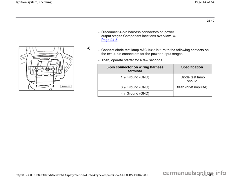
- Disconnect 4-pin harness connectors on power
output stages Component locations overview,
Page 24
-5 .
- Connect diode test lamp VAG1527 in turn to the following contacts on
the two 4-pin connectors for the power output stages.
- Then, operate starter for a few seconds.
6-pin connector on wiring harness,
terminal
Specification
1 + Ground (GND) Diode test lamp
should
3 + Ground (GND) flash (brief impulse)
4 + Ground (GND)
Pa
ge 14 of 64 I
gnition s
ystem, checkin
g
11/22/2002 htt
p://127.0.0.1:8080/audi/servlet/Dis
play?action=Goto&t
yp
e=re
pair&id=AUDI.B5.FU04.28.1
Page 16 of 64
28-14
- Rectify any open/short circuit as necessary.
If no wiring malfunction is detected:
- Connect 4-pin connectors to power output
stages.
- Disconnect 3-pin connectors from power output
stages.
- Connect diode test lamp VAG1527 to battery
(B+) and to one of the 3 terminals on power
output stage.
- Operate starter for few seconds.
The diode test lamp should flash.
- Carry out test with all 3 terminals on each of the
3-pin connectors for the power output stages.
The diode test lamp should flash each time.
Pa
ge 16 of 64 I
gnition s
ystem, checkin
g
11/22/2002 htt
p://127.0.0.1:8080/audi/servlet/Dis
play?action=Goto&t
yp
e=re
pair&id=AUDI.B5.FU04.28.1