Page 17 of 32
13-17
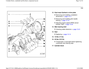
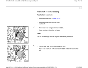
Dual mass flywheel or drive plate,
removing and installing
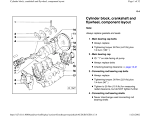
Flywheel
Note:
The needle roller bearing is in the flywheel and must be pressed in when
replacing the flywheel.
Tightening torque - Install crankshaft holder 3242 with crankshaft at Top Dead Center
(TDC) position.
- Mark relationship between flywheel and engine cylinder block (arrows).
- Remove flywheel.
Dual mass flywheel: 40 Nm (30 ft lb) plus 1/2-turn (180 )
Pa
ge 17 of 32 C
ylinder block, crankshaft and fl
ywheel, com
ponent la
yout
11/21/2002 htt
p://127.0.0.1:8080/audi/servlet/Dis
play?action=Goto&t
yp
e=re
pair&id=AUDI.B5.GE01.13.4
Page 18 of 32
13-18
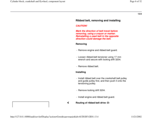
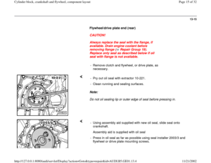
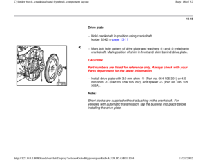
Drive plate
- Hold crankshaft in position using crankshaft
holder 3242 page 13
-11
CAUTION!
Part numbers are listed for reference only. Always check with your
Parts department for the latest information.
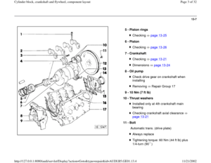
Note:
Short blocks are supplied without a bushing in the crankshaft. For
vehicles with automatic transmission, tap the bushing into place before
installing the drive plate. - Mark bolt hole pattern of drive plate and washers -1- and -2- relative to
crankshaft. Mark position of shim in front and shim behind drive plate.
- Install drive plate with 3.0 mm shim -1- (Part no. 054 105 301) or 4.0
mm shim -1- (Part no. 054 105 202), and spacer -2- (Part no. 035 105
303A).
Pa
ge 18 of 32 C
ylinder block, crankshaft and fl
ywheel, com
ponent la
yout
11/21/2002 htt
p://127.0.0.1:8080/audi/servlet/Dis
play?action=Goto&t
yp
e=re
pair&id=AUDI.B5.GE01.13.4
Page 19 of 32
13-19
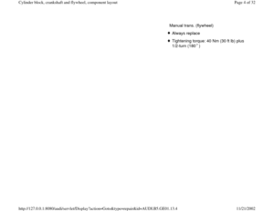
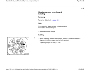
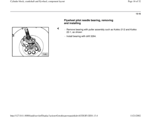
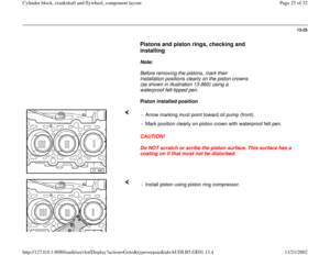
Note:
Before installing the engine, make sure that the engine-to-transmission
dowel sleeves are installed in the cylinder block flange. - Check clearance -a- between drive plate and cylinder block in three
places and calculate average value.
Dimension -a-:
Transmission 01V: 18.1-19.7 mm (0.713-0.776 in.)
- If necessary, install other shims to achieve correct clearance
dimension.
Tightening torque: 60 Nm (44 ft lb) plus 1/4-turn (90 )
Pa
ge 19 of 32 C
ylinder block, crankshaft and fl
ywheel, com
ponent la
yout
11/21/2002 htt
p://127.0.0.1:8080/audi/servlet/Dis
play?action=Goto&t
yp
e=re
pair&id=AUDI.B5.GE01.13.4
Page 20 of 32
13-20
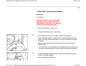
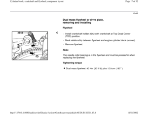
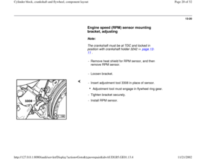
Engine speed (RPM) sensor mounting
bracket, adjusting
Note:
The crankshaft must be at TDC and locked in
position with crankshaft holder 3242 page 13
-
11
.
- Remove heat shield for RPM sensor, and then
remove RPM sensor.
- Loosen bracket.
- Insert adjustment tool 3308 in place of sensor.
Adjustment tool must engage in flywheel ring gear.
- Tighten bracket securely.
- Install RPM sensor.
Pa
ge 20 of 32 C
ylinder block, crankshaft and fl
ywheel, com
ponent la
yout
11/21/2002 htt
p://127.0.0.1:8080/audi/servlet/Dis
play?action=Goto&t
yp
e=re
pair&id=AUDI.B5.GE01.13.4
Page 21 of 32
13-21
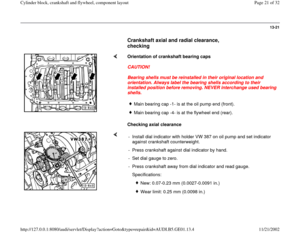
Crankshaft axial and radial clearance,
checking
Orientation of crankshaft bearing caps
CAUTION!
Bearing shells must be reinstalled in their original location and
orientation. Always label the bearing shells according to their
installed position before removing. NEVER interchange used bearing
shells.
Checking axial clearance
Main bearing cap -1- is at the oil pump end (front).Main bearing cap -4- is at the flywheel end (rear).
- Install dial indicator with holder VW 387 on oil pump and set indicator
against crankshaft counterweight.
- Press crankshaft against dial indicator by hand.
- Set dial gauge to zero.
- Press crankshaft away from dial indicator and read gauge.
Specifications:
New: 0.07-0.23 mm (0.0027-0.0091 in.)
Wear limit: 0.25 mm (0.0098 in.)
Pa
ge 21 of 32 C
ylinder block, crankshaft and fl
ywheel, com
ponent la
yout
11/21/2002 htt
p://127.0.0.1:8080/audi/servlet/Dis
play?action=Goto&t
yp
e=re
pair&id=AUDI.B5.GE01.13.4
Page 22 of 32
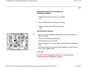
13-22
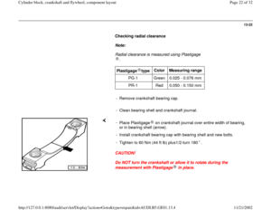
Checking radial clearance
Note:
Radial clearance is measured using Plastigage
.
Plastigage type
Color
Measuring range
PG-1 Green 0.025 - 0.076 mm
PR-1 Red 0.050 - 0.150 mm
- Remove crankshaft bearing cap.
- Clean bearing shell and crankshaft journal.
CAUTION!
Do NOT turn the crankshaft or allow it to rotate during the
measurement with Plastigage in place. -
Place Plastigage on crankshaft journal over entire width of bearing,
or in bearing shell (arrow). - Install crankshaft bearing cap with bearing shell and new bolts.
-
Tighten to 60 Nm (44 ft lb) plus1/2-turn 180 .
Pa
ge 22 of 32 C
ylinder block, crankshaft and fl
ywheel, com
ponent la
yout
11/21/2002 htt
p://127.0.0.1:8080/audi/servlet/Dis
play?action=Goto&t
yp
e=re
pair&id=AUDI.B5.GE01.13.4
Page 23 of 32
13-23
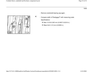
- Remove crankshaft bearing cap again.
-
Compare width of Plastigage with measuring scale. Specifications:
New: 0.018-0.045 mm (0.0007-0.0018 in.)
Wear limit: 0.10 mm (0.0039 in.)
Pa
ge 23 of 32 C
ylinder block, crankshaft and fl
ywheel, com
ponent la
yout
11/21/2002 htt
p://127.0.0.1:8080/audi/servlet/Dis
play?action=Goto&t
yp
e=re
pair&id=AUDI.B5.GE01.13.4
Page 24 of 32
 Connecting rod journal
diameter - mm (in.)
maximum size (from nominal) -0.022 (0.00087)")
13-24
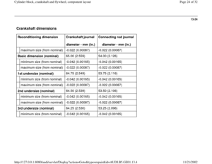
Crankshaft dimensions
Reconditioning dimension
Crankshaft journal
diameter - mm (in.) Connecting rod journal
diameter - mm (in.)
maximum size (from nominal) -0.022 (0.00087) -0.022 (0.00087)
Basic dimension (nominal) 65.00 (2.559) 54.00 (2.126)
minimum size (from nominal) -0.042 (0.00165) -0.042 (0.00165)
maximum size (from nominal) -0.022 (0.00087) -0.022 (0.00087)
1st undersize (nominal) 64.75 (2.549) 53.75 (2.116)
minimum size (from nominal) -0.042 (0.00165) -0.042 (0.00165)
maximum size (from nominal) -0.022 (0.00087) -0.022 (0.00087)
2nd undersize (nominal) 64.50 (2.539) 53.50 (2.106)
minimum size (from nominal) -0.042 (0.00165) -0.042 (0.00165)
maximum size (from nominal) -0.022 (0.00087) -0.022 (0.00087)
3rd undersize (nominal) 64.25 (2.530) 53.25 (2.096)
minimum size (from nominal) -0.042 (0.00165) -0.042 (0.00165)
Pa
ge 24 of 32 C
ylinder block, crankshaft and fl
ywheel, com
ponent la
yout
11/21/2002 htt
p://127.0.0.1:8080/audi/servlet/Dis
play?action=Goto&t
yp
e=re
pair&id=AUDI.B5.GE01.13.4


 sensor mounting
bracket, adjusting
Note:
The crankshaft must be at TDC and locked in
position with crankshaft holder 3242 page 13
-
11
.
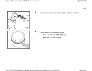
- R")


Wear limit: 0.10 mm (0.0039")