Page 11 of 738
Page 48 of 738

Downloaded from www.Manualslib.com manuals search engine 46CONFIGURATION DIAGRAMS - Engine and Transaxle
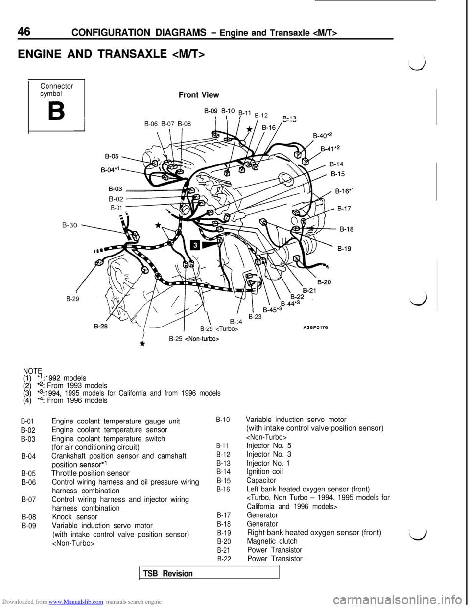
ENGINE AND TRANSAXLE :
Connector
symbol
B
Front View
B-0: B;lO 53-11B-12R-i?
IB-06 B-07 B-08B-40*’
B-02
------+
B-01B-30
\ 7
I
B-29
- \B-:4B-23
B-25
A36F0176
B-01
B-02
B-03
B-04
B-05
B-06
B-07
B-08
B-09
i*B-25
NOTE
[:I*‘A992 models*2: From 1993 models*s:1994, 1995 models for California and from 1996 models*4: From 1996 models
Engine coolant temperature gauge unit
Engine coolant temperature sensor
Engine coolant temperature switch(for air conditioning circuit)
Crankshaft position sensor and camshaftposition
sensor*’Throttle position sensor
Control wiring harness and oil pressure wiring
harness combination
Control wiring harness and injector wiring
harness combination
Knock sensor
Variable induction servo motor
(with intake control valve position sensor)
B-10
B-11
B-12
B-13
B-14
B-15
B-16
B-17
B-18
B-19
B-20
B-21
B-22
Variable induction servo motor(with intake control valve position sensor)
Injector No. 5
Injector No. 3
Injector No. 1
Ignition coil
Capacitor
Left bank heated oxygen sensor (front)
- 1994, 1995 models for
California and 1996 models>
Generator
GeneratorRight bank heated oxygen sensor (front)
Magnetic clutch
Power Transistor
Power TransistorL)
TSB Revision
Page 49 of 738
Downloaded from www.Manualslib.com manuals search engine B-23
B-24
B-25
B-28
B-29
B-30
B-31
B-32
B-33
Rear View
B-46*4
B-32
B-33
A36F0167
Starter motor
Starter motor
Back-up light switchFuel pump relay
Volume air flow sensor (with intake air
temperature sensor and atmospheric sensor)
Control wiring harness and battery cable
combination
Injector No. 2
Injector No. 4
Injector No. 6
B-34
B-35
B-36
B-37
B-38
B-40
B-41
B-44
B-45B-46
Speed sensor
Idle air control motor (stepper motor)
Oil pressure gauge unit
Oil pressure switch
Power steering pressure switch
Camshaft position
sensor*2
Crankshaft position sensor*2Right bank heated oxygen sensor
(rear)*3Left bank heated oxygen sensor
(rear)*3Manifold differential pressure
sensor*4
CONFIGURATION DIAGRAMS - Engine and Transaxle 47
TSB Revision
Page 50 of 738
Page 51 of 738
Page 166 of 738

Downloaded from www.Manualslib.com manuals search engine CIRCUIT DIAGRAMS - MFI Circuit
COMPONENT LOCATIONUp to 1993 models and 1994, 1995 models Non Turbo (Federal)
NameSymbol
Air conditioning relay0
Air conditioning switch
Camshaft position sensor
a
Check engine/malfunction indicator lampP
Crankshaft position sensorD
Data link connectorR
EGR solenoid Z
EGR temperature sensor
Engine control module
Engine coolant temperature sensor
Evaporative emission purge solenoid
Fuel pressure solenoid
Heated oxygen sensorE
idle air control motor (stepper motor)L
Name/ Symbol
Ignition coil (ignition power transistor)
Ignition timing adjusting terminal
Injector
(1
Multrport fuel rnjectron (MFI) relay
ParWNeutral position switch c&T>
Power steering pressure switchH
Resistor W
Throttle position sensor (With built-in closed throttleCposition switch)
Turbocharger waste gate solenoid U
Variable induction control motor (DC motor) (withJbuilt-in induction control valve position sensor)
Vehicle speed sensorFIVolume air flow sensor (with built-in intake air A
temperature sensor and barometric pressure sensor)
1 TSB Revision
Page 171 of 738
Downloaded from www.Manualslib.com manuals search engine CIRCUIT DIAGRAMS - MFI Circuit169
i
L
iJ
1994, 1995 models except Non Turbo (Federal) and from 1996 models
Evaporative emission purge solenoid
Fuel pressure solenoid
Heated oxygen sensor
Idle air control motor (stepper motor)
Ignition coil (ignition power transistor)
XTurbocharger waste gate solenoid
V
Variable induction control motor (DC motor) (with
Ebuilt-in induction control valve position sensor)
LVehicle speed sensor
MVolume air flow sensor (with built-in intake airtemperature sensor and barometric pressure sensor)Symbol
Q
K
T
E
Y
N
I
H
W
E
C
U
J
F
A
TSB Revision
Page 507 of 738
Downloaded from www.Manualslib.com manuals search engine CHASSIS ELECTRICAL - Meters and Gauaes
SERVICE SPECIFICATIONS
Items
Standard values
Speedometer indicationerror
mph
2019-22
4038-44
1 57-66
1 76-88I
1001 94-110I
Tachometerindicationerrorrpm1,000f 100
3,000
f150
5,000f 250
6,000
Ik 300
Fuel gauge unit resistance R/ Point F_I3f2I
Point E
Fuel gauge unit float heightPoint F
mm (in.)
Point E
Engine coolant temperature gauge unit resistance [at 70°C (158”F)] Q110+7
18.6-21.6 (.73-.85)193.4-l
96.4 (7.61-7.73)
104 f 13.5
Fuel gauge resistance QBetween A - B/ Approx. 254I
Between A - CApprox. 101I
Between B - CApprox. 153I
Enginecoolant temperature Between A - B
gauge resistance QBetween A - CApprox. 51
Approx. 139
Between B
- C/ Approx. 190I
Oil pressure gauge resistance QApprox. 42I
Pressure gauge resistance QApprox. 72ISEALANT
ItemsSpecified sealantType
Engine coolant temperature gauge3M Nut Locking Part No. 4171 or Semi-drying sealant
unitequivalent
TSB Revision