Page 1029 of 1708
T SRS AIR BAG SYSTEM I Flowchart No.16 I Symptom I Service Code 51 I Possible cause Blown internal fuse in diagnostic module (fault conditions no longer present) 0 Diagnostic module not replaced after service code 13 set and conditions corrected. Intermittent short in air bag deployment circuit. Remedy If repairs were made for a service code 13, replace the diagnostic module. If an intermittent short is sus- pected, inspect the wiring harnesses and connectors for damage. If they are not damaged, wiggle the harnesses and connectors to induce the intermittent short; service code 13 will be set when the fault is induced. Then follow the troubleshooting procedure for service code 13. 36EOTX-143 Gartner Banana
Page 1035 of 1708
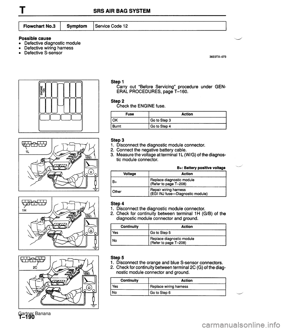
T SRS AIR BAG SYSTEM Possible cause ij Defective diagnostic module Defective wiring harness Defective S-sensor Step 1 Carry out "Before Servicing" procedure under GEN- ERAL PROCEDURES, page T-1 60. Service Code 12 Flowchart No.3 Step 2 Check the ENGINE fuse. Fuse Action I Symptom Step 3 1. Disconnect the diagnostic module connector. 2. Connect the negative battery cable. 3. Measure the voltage at terminal 1 L (WIG) of the diagnos- OK Burnt tic module connector. Go to Step 3 Go to Step 4 B+: Battery positive voltage - Other Repair wiring harness iEGI INJ fuss-Diaanostic module1 I Voltage B+ -- ~ Action Replace diagnostic module (Refer to page T-208) I NO Replace diagnostic module (Refer to Daae T-2081 Step 4 1. Disconnect the diagnostic module connector. 2. Check for continuity between terminal 1 H (GIB) of the diagnostic module connector and ground. Step 5 1. Disconnect the orange and blue S-sensor connectors. 2. Check for continuity between terminal 2C (G) of the diag- nostic module connector and ground. 1 Continuity Action 1 Continuity Yes Action Go to Step 5 Yes No Replace wiring harness Go to Step 6 L Gartner Banana
Page 1036 of 1708
SRS AIR BAG SYSTEM Step 6 Check for continuity between terminal 1H (G/B) of the diagnostic module connector and ground. I Flowchart No.4 I Symptom I Service Code 21 I Continuity Yes I No I Replace S-sensor (Refer to page T-213) I Action Replace air bag wiring harness and EGI INJ fuse Possible cause Defective S-sensor Defective wiring harness Defective diagnostic module Step 1 Carry out "Before Servicing" procedure under GEN- ERAL PROCEDURES, page T-1 60. Step 2 1. Disconnect the diagnostic module connector. 2. Check for continuity between terminal 1 E (RIB) of the diagnostic module connector and ground. I Continuitv Action 1 Yes Replace diagnostic module (Refer to page T-208) I NO I GO to step 3 Step 3 1. Disconnect the orange and blue S-sensor connectors. 2. Check for continuity between terminal A of the S-sensor and ground. Continuity 1 Action I 1 yes I Replace wiring harness I I No I Replace S-sensor (Refer to page T-213) I Gartner Banana
Page 1047 of 1708
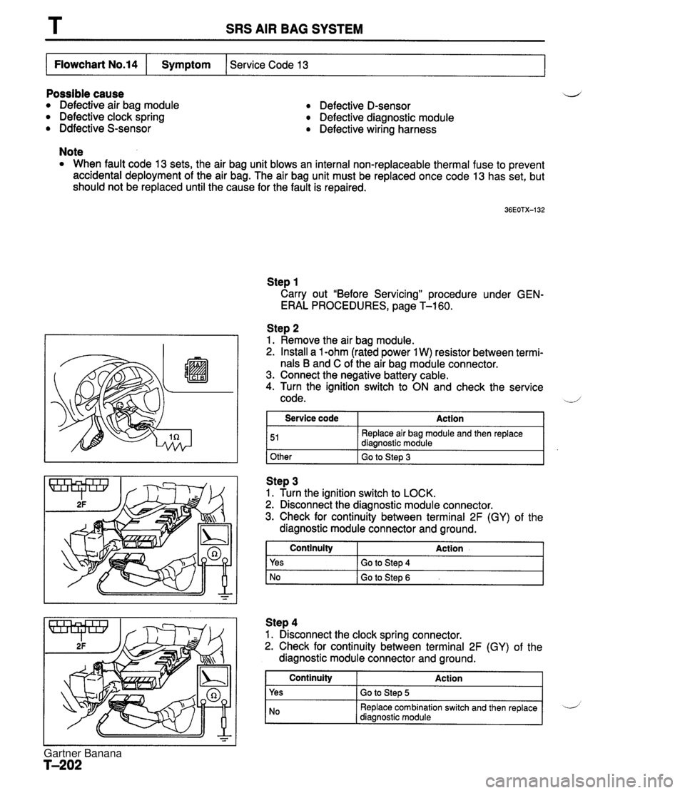
SRS AIR BAG SYSTEM Possible cause Defective air bag module Defective clock spring Ddfective S-sensor Defective D-sensor Defective diagnostic module Defective wiring harness Service Code 13 Flowchart No.14 Note When fault code 13 sets, the air bag unit blows an internal non-replaceable thermal fuse to prevent accidental deployment of the air bag. The air bag unit must be replaced once code 13 has set, but should not be replaced until the cause for the fault is repaired. Symptom Step 1 Carry out "Before Servicing" procedure under GEN- ERAL PROCEDURES, page T-1 60. Step 2 1. Remove the air bag module. 2. Install a 1 -ohm (rated power 1 W) resistor between termi- nals B and C of the air bag module connector. 3. Connect the negative battery cable. 4. Turn the ignition switch to ON and check the service d 1 code. 1 Other I Go to Step 3 Service code 51 Step 3 1. Turn the ianition switch to LOCK. Action Replace air bag module and then replace diagnostic module 2. ~isconnegt the diagnostic module connector. 3. Check for continuity between terminal 2F (GY) of the diagnostic module connector and ground. I Continuity Action 1 Step 4 1. Disconnect the clock spring connector. 2. Check for continuity between terminal 2F (GY) of the diagnostic module connector and ground. Yes No Continuity Yes Go to Step 4 Go to Step 6 Gartner Banana
Page 1049 of 1708
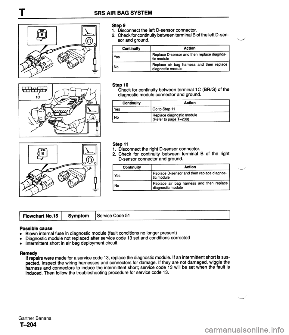
T SRS AIR BAG SYSTEM Step 9 1. Disconnect the left D-sensor connector. 2. Check for continuity between terminal B of the left D-sen- sor and ground. il I Continuity I Action I Step 10 Check for continuity between terminal 1 C (BRIG) of the diagnostic module connector and ground. I Continuity Action 1 Yes No I Yes I GO to step 11 Replace D-sensor and then replace diagnos- tic module Replace air bag harness and then replace diagnostic module Step 11 1. Disconnect the right D-sensor connector. 2. Check for continuity between terminal B of the right No D-sensor connectoiand ground. Replace diagnostic module (Refer to page T-208) Continuity Action Replace D-sensor and then replace diagnos- tic module Replace air bag harness and then replace I Flowchart No.15 I Symptom 1 Service Code 51 I Possible cause Blown internal fuse in diagnostic module (fault conditions no longer present) Diagnostic module not replaced after service code 13 set and conditions corrected Intermittent short in air bag deployment circuit Remedy If repairs were made for a service code 13, replace the diagnostic module. If an intermittent short is sus- pected, inspect the wiring harnesses and connectors for damage. If they are not damaged, wiggle the harness and connectors to induce the intermittent short; service code 13 will be set when the fault is induced. Then follow the troubleshooting procedure for service code 13. Gartner Banana
Page 1066 of 1708
Ix-ozl MAIN FUSE eLOCK MAIN AD FAN IX-071 L/Y (€1 \ G-01 G -01 FRONT (F) -A/C IAC) G-02 MAGNETIC CLUTCH (F) G-03 BLOHER WIT (F) 16-04 ?$WER&TVRE SNITCt .CONDENSOR FAN .HEATER AND AIR CONDITIONER I I '07 CONENSOR FAN (AC) G-08 REFRIGERANT PflESSURE SWITCH (AC) IG-09 A/C RELAY (ACI 16- 10 COMENSER FAN RELAY (AC) Gartner Banana
Page 1067 of 1708
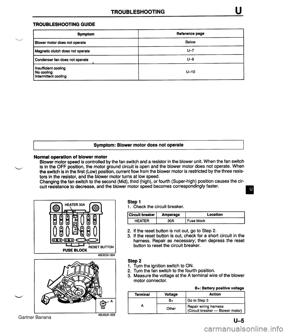
TROUBLESHOOTING u TROUBLESHOOTING GUIDE I Symptom Blower motor does not operate Reference page Below Magnetic clutch does not operate I U-7 Condenser fan does not operate e Symptom: Blower motor does not operate I U-9 Insufficient cooling No cooling Intermittent cooling Normal operation of blower motor Blower motor speed is controlled by the fan switch and a resistor in the blower unit. When the fan switch L is in the OFF position, the motor ground circuit is open and the blower motor does not operate. When the switch is in the first (Low) position, current flow from the blower motor is restricted by the three resis- tors in the resistor, and the blower motor turns at low speed. Changing the fan switch to the second (Mid), third (high), or fourth (Super-high) position causes the cir- cuit resistance to decrease, and the blower motor speed becomes correspondingly faster. I l U-10 (-1 (rn) I I I RESET BUTTON FUSE BLOCK Step 1 1. Check the circuit breaker. 2. If the reset button is not out, go to Step 2. 3. If the reset button is out, check for a short circuit in the harness. Repair as necessary; then depress the reset button to reset the circuit breaker. circuit breaker HEATER Step 2 1. Turn the ignition switch to ON. 2. Turn the fan switch to the fourth position. 3. Measure the voltage at the A terminal wire of the blower motor connector. B+: Battery positive voltage I Terminal I Voltage Action I Amperage 30A Location Fuse block A U-5 Bt Other Go to Step 3 Repair wiring harness (Circuit breaker - Blower motor) Gartner Banana
Page 1069 of 1708
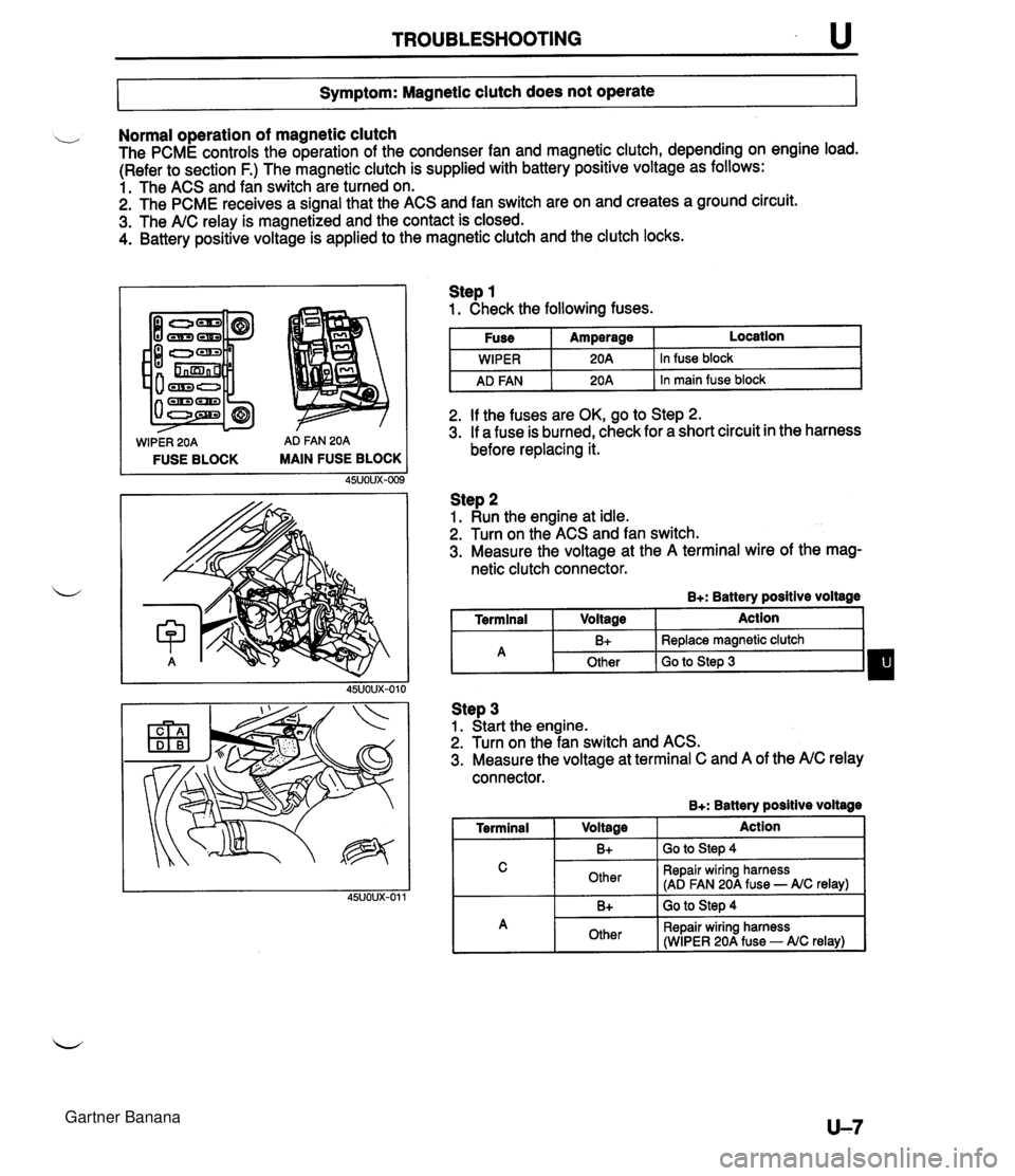
TROUBLESHOOTING u 7- Symptom: Magnetic clutch does not operate I Normal operation of magnetic clutch The PCME controls the operation of the condenser fan and magnetic clutch, depending on engine load. (Refer to section F.) The magnetic clutch is supplied with battery positive voltage as follows: 1. The ACS and fan switch are turned on. 2. The PCME receives a signal that the ACS and fan switch are on and creates a ground circuit. 3. The A/C relay is magnetized and the contact is closed. 4. Battery positive voltage is applied to the magnetic clutch and the clutch locks. WIPER 20A AD FAN 20A FUSE BLOCK MAIN FUSE BLOCK Step 1 1. Check the following fuses. I Fuse I Amperage I Location I I I . - I WIPER I 20A 1 In fuse block I I AD FAN I 20A 1 In main fuse block I 2. If the fuses are OK, go to Step 2. 3. If a fuse is burned, check for a short circuit in the harness before replacing it. Step 2 1. Run the engine at idle. 2. Turn on the ACS and fan switch. 3. Measure the voltage at the A terminal wire of the mag- netic clutch connector. B+: Battery positive voltage I Terminal I Voltage I Action 1 Step 3 1. Start the engine. 2. Turn on the fan switch and ACS. 3. Measure the voltage at terminal C and A of the A/C relay connector. B+: Batterv positive voltaae - -- A 1 Terminal I V0lta0e 1 Action I I C I Other I Repair wiring harness (AD FAN 20A fuse - AIC relay) I B+ Other I 1. -. B+ I GO to step 4 Replace magnetic clutch Go to Step 3 I A 1 Other I Repair wiring harness (WIPER 20A fuse - AIC relay) I Gartner Banana