Page 1051 of 1708

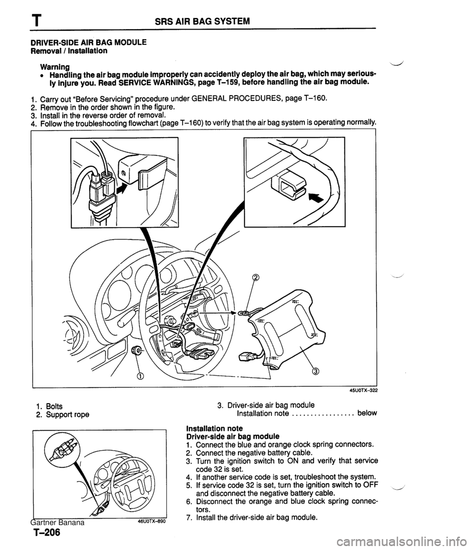
SRS AIR BAG SYSTEM DRIVER-SIDE AIR BAG MODULE Removal I Installation Warning 4 Handling the air bag module improperly can accidently deploy the air bag, which may serious- ly injure you. Read SERVICE WARNINGS, page T-159, before handling the air bag module. 1. Carry out "Before Servicing" procedure under GENERAL PROCEDURES, page T-160. 2. Remove in the order shown in the figure. 3. Install in the reverse order of removal. 4. Follow the troubleshootina flowchart (page T-160) to verify that the air bag system is operating normally. 1. Bolts 2. Support rope 3. Driver-side air bag module Installation note . . . . . . . . . . . . . . . . . below Installation note Driver-side air bag module 1. Connect the blue and orange clock spring connectors. 2. Connect the negative battery cable. 3. Turn the ignition switch to ON and verify that service code 32 is set. 4. If another service code is set, troubleshoot the system. 5. If service code 32 is set, turn the ignition switch to OFF and disconnect the negative battery cable. 6. Disconnect the orange and blue clock spring connec- tors. 7. Install the driver-side air bag module. Gartner Banana
Page 1052 of 1708

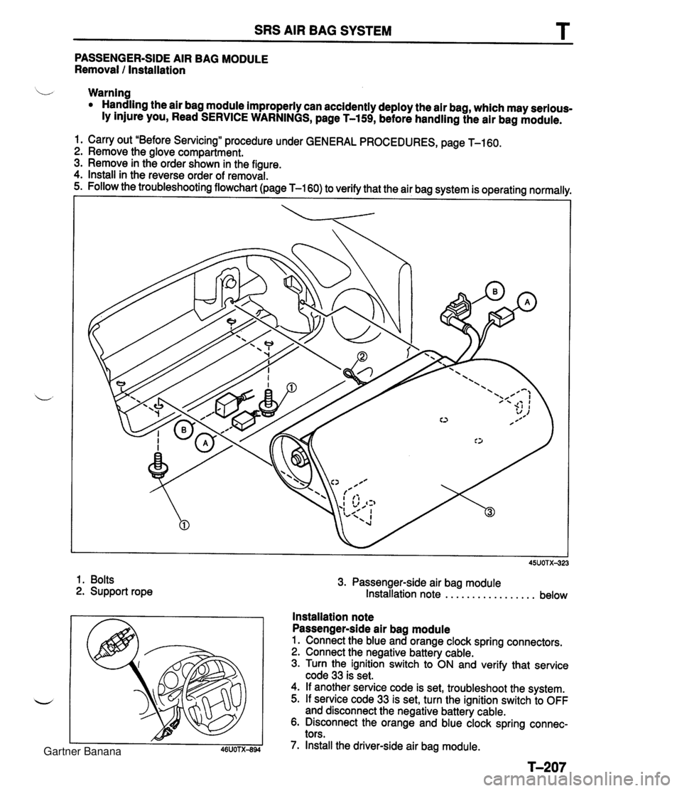
SRS AIR BAG SYSTEM T PASSENGER-SIDE AIR BAG MODULE Removal I Installation b Warning Handling the air bag module improperly can accidently deploy the air bag, which may serious- ly injure you, Read SERVICE WARNINGS, page T-159, before handling the air bag module. 1. Carry out "Before Servicing" procedure under GENERAL PROCEDURES, page T-160. 2. Remove the glove compartment. 3. Remove in the order shown in the figure. 4. Install in the reverse order of removal. 1. Bolts 2. Support rope 3. Passenger-side air bag module Installation note . . . . . . . . . . . . . . . . . below Installation note Passenger-side air bag module 1. Connect the blue and orange clock spring connectors. 2. Connect the negative battery cable. 3. Turn the ignition switch to ON and verify that service code 33 is set. 4. If another service code is set, troubleshoot the system. 5. If service code 33 is set, turn the ignition switch to OFF and disconnect the negative battery cable. 6. Disconnect the orange and blue clock spring connec- tors. 7. Install the driver-side air bag module. Gartner Banana
Page 1054 of 1708

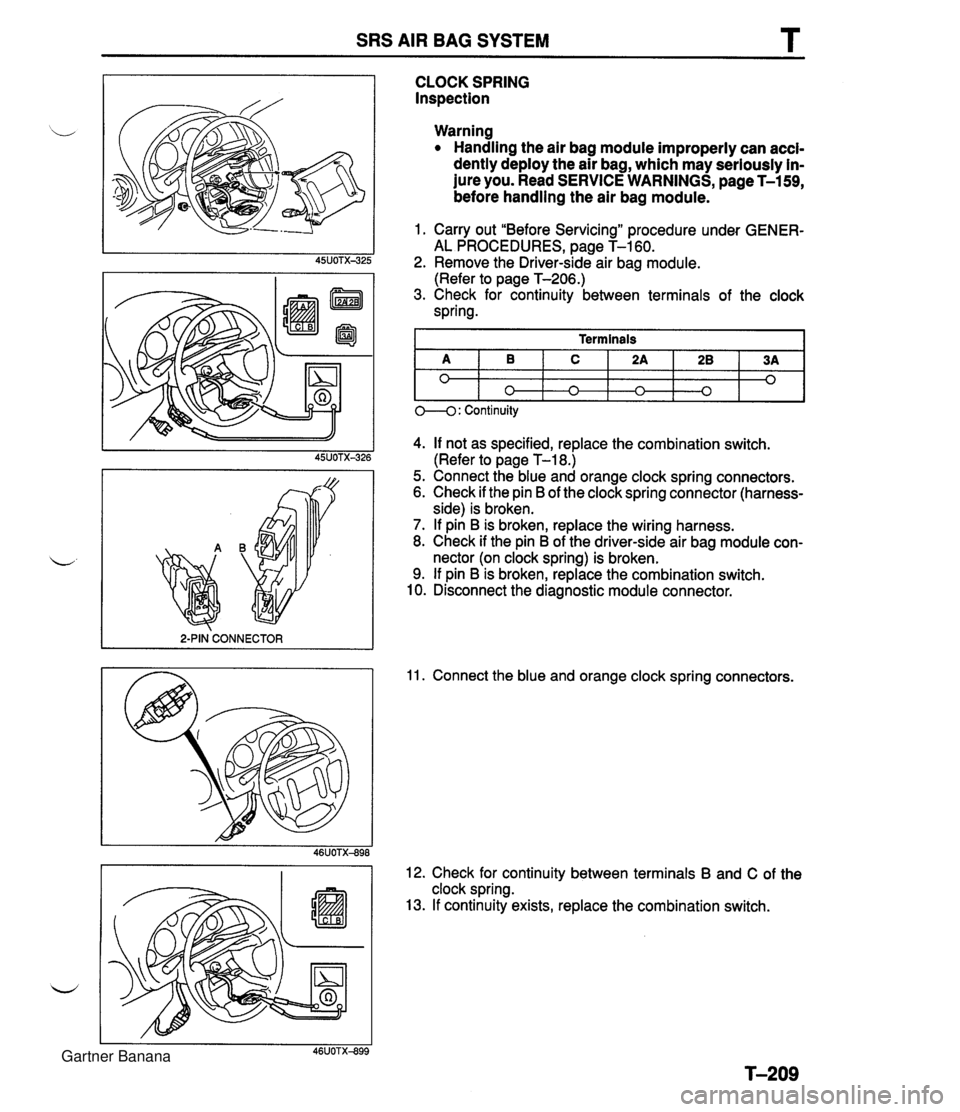
SRS AIR BAG SYSTEM T 2-PIN CONNECTOR I CLOCK SPRING Inspection Warning Handling the air bag module improperly can accl- dently deploy the air bag, which may seriously in- jure you. Read SERVICE WARNINGS, page T-159, before handling the air bag module. 1. Carry out "Before Servicing" procedure under GENER- AL PROCEDURES, page T-160. 2. Remove the Driver-side air bag module. (Refer to page T-206.) 3. Check for continuity between terminals of the clock spring. 4. If not as specified, replace the combination switch. (Refer to page T-18.) 5. Connect the blue and orange clock spring connectors. 6. Check if the pin B of the clock spring connector (harness- side) is broken. 7. If pin B is broken, replace the wiring harness. 8. Check if the pin B of the driver-side air bag module con- nector (on clock spring) is broken. 9. If pin B is broken, replace the combination switch. 10. Disconnect the diagnostic module connector. Terminals 11. Connect the blue and orange clock spring connectors. A 0 12. Check for continuity between terminals B and C of the clock spring. 13. If continuity exists, replace the combination switch. 1 0---0: Continuity B 0 C n 2A n 28 0 3A 0 Gartner Banana
Page 1060 of 1708

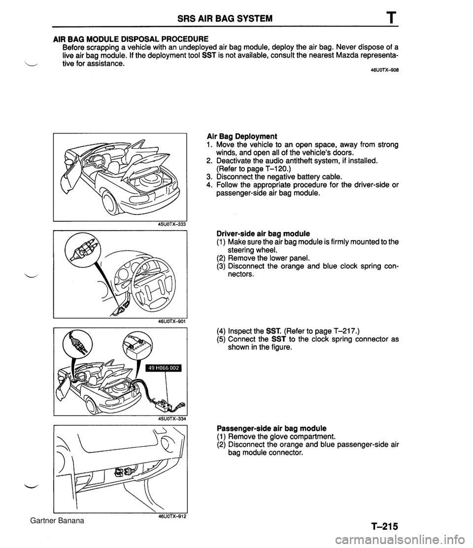
SRS AIR BAG SYSTEM T AIR BAG MODULE DISPOSAL PROCEDURE Before scrapping a vehicle with an undeployed air bag module, deploy the air bag. Never dispose of a live air bag module. If the deployment tool SST is not available, consult the nearest Mazda representa- i/ tive for assistance. 46UOTX-908 Air Bag Deployment 1. Move the vehicle to an open space, away from strong winds, and open all of the vehicle's doors. 2. Deactivate the audio antitheft system, if installed. (Refer to page T-120.) 3. Disconnect the negative battery cable. 4. Follow the appropriate procedure for the driver-side or passenger-side air bag module. Driver-side air bag module (1 ) Make sure the air bag module is firmly mounted to the steering wheel. (2) Remove the lower panel. (3) Disconnect the orange and blue clock spring con- nectors. (4) Inspect the SST. (Refer to page T-217.) (5) Connect the SST to the clock spring connector as shown in the figure. Passenger-side air bag module (1) Remove the glove compartment. (2) Disconnect the orange and blue passenger-side air bag module connector. Gartner Banana
Page 1062 of 1708
SRS AIR BAG SYSTEM T INSPECTION OF SST (DEPLOYMENT TOOL) Use the SST (deployment tool) to deploy a live air bag module before disposing of it. Before connecting the SST to the clock spring connector or air bag module connector, inspect operation b of the SST. CONNECTOR B CONNECTOR A STEP 1 RED @ STEP 2 ACTIVATION SWITCH I 29UOTX-357 lnspection Procedure 1. Inspect operation of the SST by following the steps be- low. 1 1 3 1 Press activation switch I ON I OFF I - Connect connectors A and B of ST 2. If not as specified, do not use the SST because it may cause the air bag to unexpectedly deploy upon connec- tion to the module. Connect red clip to positive bat- tery terminal and black clip to nenative battery terminal OFF ON OFF OFF Gartner Banana
Page 1368 of 1708
lU3O -1 % CYLINDER B!OCL CLOCK,CYLIUDER JETIOIL =LUG PIti, TUBULAR JOI Ell PIPE ,OIL LEVEL GAUGE PLUG, BLIt1D BOLT 1 BEARIKG CAP GAUGE,OIL LEVEL RING, '0' GASKET ,011. JE'f VALVE ,OIL .JET PLUG Gartner Banana