Page 414 of 1708

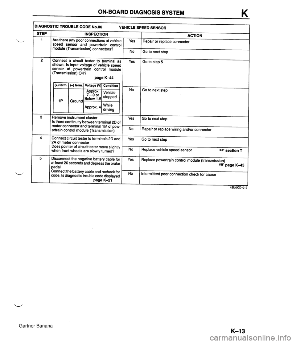
ON-BOARD DIAGNOSIS SYSTEM K )IAGNOSTIC TROUBLE CODE N0.06 VEHICLE SPEED SENSOR INSPECTION STEP ACTION Repair or replace connector Are there any poor connections at vehicle speed sensor and powertrain control module (Transmission) connectors? Yes Go to next step Connect a circuit tester to terminal as shown. Is input voltage of vehicle speed sensor at powertrain control module (Transmission) OK? page K-44 Yes Go to step 5 1 (+) term. I (-) term. ( Voltage (v)( Condition I Go to next step Below 1.5 While Remove instrument cluster Is there continuity between terminal 2D of meter connector and terminal 1 M of pow- ertrain control module (Transmission) Yes Go to next step Repair or replace wiring and/or connector Connect circuit tester to terminals 2D and 2A of meter connector Does pointer of circuit tester move slightly when front wheels are slowly turned? Yes Go to next step Replace vehicle speed sensor section T Disconnect the negative battery cable for at least 20 seconds and depress the brake pedal Connect the battery cable and recheck for code. Is diagnostic trouble code displayed Dane K-21 Yes Replace powertrain control module (transmission) page K-45 Intermittent poor connection check for cause Gartner Banana
Page 439 of 1708

K ELECTRICAL SYSTEM COMPONENTS ELECTRICAL SYSTEM COMPONENTS PREPARATION SST 49 GO1 8 904 Sheet 49 9200 162 Monitor, Engine Signal - 49 DO1 9 902 Adapter Harness For inspection of powertrain control module (transmission) terminal voltage For inspection of powertrain control module (transmission) terminal voltage p@ HOLD For inspection of powertrain control module (transmission) terminal voltage HOLD SWITCH lnspection lnspection of operation 1. Turn the ignition switch from OFF to ON. 2. Verify that the hold indicator light is not illuminated. De- press the hold switch and verify that the hold indicator -J light illuminates. 3. If not as specified, check the terminal voltage of the hold switch. lnspection of voltage 1. Remove the front console. 2. Turn the ignition switch ON. 3. Measure voltage at the hold switch connector. B+: Battery positive voltage Position (V): Voltage Normal (V) Depressed (V) 4. If not as specified, check the continuity of the hold switch. Connector terminal A B+ 0 B 0 0 Gartner Banana
Page 440 of 1708

ELECTRICAL SYSTEM COMPONENTS K Replacement 1. Disconnect the negative battery cable. 2. Remove the front console. 3. Remove the indicator panel installation screws. 4. Disconnect the connector and remove the hold switch terminals. 5. Remove the selector lever knob assembly. 6. lnstall a new selector lever knob assembly. lnspection of continuity 1. Disconnect the negative battery cable. 2. Disconnect the hold switch connector. 3. Check continuity of the switch. Tightening torque: 2.0-2.9 N.m (20-30 kgfscm, 18-26 in-lbf) Position Normal Depressed 7. lnstall the hold switch terminals and connect the connec- tor. 8. lnstall the indicator panel installation screws. (Refer to page K-163.) 9. lnstall the front console. 10. Connect the negative battery cable. PARKINEUTRAL SWITCH lnspection lnspection of operation 1. Verify that the starter operates only with the ignition switch at the START position and the selector lever in P and N ranges. 2. Verify that the back-up lights illuminate when shifted to R range with the ignition switch in the ON position. 3. Verify that the positions of the selector lever and the se- lector indicator light of the instrument cluster are aligned. 4. Check the ParkINeutral switch if not as specified. 0--4: Continuity 45UOKX-525 4. If not as specified, replace the selector lever knob as- sembly. (Refer to below.) 5. If the switch is OK, check the wiring harness. (Hold switch - powertrain control module (transmission), Hold switch - Body ground.) 6. lnstall the front console. 7. Connect the negative battery cable. Terminal A 0 B 0 Gartner Banana
Page 445 of 1708

K ELECTRICAL SYSTEM COMPONENTS Terminal Voltage Chart (Reference Data) C Terminal B+: Battery positlve voltage y Hold indicator light Condition Connected to 16 (Output) B+ Below 1.5V - - - No hold mode Hold mode FAT terminal (data link connector) I IC Voltage - - Voltmeter B+ Below 1.5V or B+ I C (Output) - - -- -- - - - -- -- - - - - - - - A- +terminal Normal If malfunction resent Ground (fluctuating) I Code Sianal I TAT terminal wounded -terminal Powertrain control module (Engine) (terminal R) TAT terminal (data link connector) - I - Below 2.5V 1 N or P range 1 D (Output) I Bt ]Other ranges I 1 E (lnput) 1 F 1 G I ATF thermosensor I 1G 3.3V ATF temperature 25OC {77"F) Ground B+ Switch depressed .-,/ -~ - 1 H (Input) 1 I Hold switch 1 OV ] Switch released I I 1 J (Output) 1 K 1 M (lnput) Cruise control unit I lM 1 N (lnput) Powertrain control module (Engine) (terminal 3M) 1 lN Idle switch B+ OV - -- Ve Accelerator pedal released I ADDrox. 4V While drivina Water temperature above 60°C {I 40°F) Accelerator pedal de~ressed Below 1.5V Vehicle speed sensor 1 P (lnput) 1 P I Approx' I Ignition switch ON I 4.4-5.5V 2A (Input) Throttle position sensor 1 2A . . . - . - . OV I lanition switch OFF 1 ParWneutral switch (N and P ranges) I OV I N or P ranae I 26 (Input) I B+ I Other ranaes I Gartner Banana
Page 451 of 1708

TRANSMISSION TRANSMISSION UNIT (DISASSEMBLY) Preparation SST 49 H075 4958 Body (Part of 49 U019 OAOA) For disassembly of transmission For disassembly of transmission For disassembly of transmission 49 U019 OAOA Hanger set, transmission 49 U019 003 Holder (Part of 49 U019 OAOA) For disassembly of transmission For disassembly of transmission Precaution General notes: 1. The oil pan could contain small chips, shavings, and other particles helpful in checking the condition of the transmission and diagnosing certain problems. To ensure that all foreign particles stay in the oil pan, make sure that the transmission is never tipped completely over while the oil pan is still installed. L/ 2. Disassemble transmission in a clean area (dust proof work space) to prevent entry of dust into the mech- anisms. 3. Inspect the individual transmission components in accordance with the QUICK DIAGNOSIS CHART during disassembly. 4. Use only plastic hammers when applying force to separate the light alloy case joints. 5. Never use rags during disassembly; they may leave particles that can clog fluid passages. 6. Several parts resemble one another; organize them so they do not get mixed up. 7. Disassemble the control valve assembly and thoroughly clean it when a clutch or brake band is burned; or when the ATF has degenerated. Cleaning notes: 1. Clean the transmission exterior thoroughly with steam or cleaning solvents, or both, before disassembly. Warning Using compressed air can cause dirt and other particles to fly out, causing injury to the eyes. Wear protective eye wear whenever using compressed air. 2. Clean the removed parts with cleaning solvent, and dry with compressed air. Clean out all holes and passages with compressed air, and check that there are no obstructions. Gartner Banana
Page 460 of 1708
TRANSMISSION K 29. Remove the bearing races and bearing. 30. Remove the intermediate shaft. I 45UOKX-116 31. Loosen the 2nd band servo locknut and tighten the pis- ton stem. I 1 45UOKX-117 32. Separate the drum support, accumulator and fourth gear case from the transmission case by tapping it lightly with a plastic hammer. Remove the gasket. u 45UOKX-118 Remove the bearing races and bearing from the drum support, accumulator and fourth gear case. Remove the bearing from the front clutch hole. Loosen the 2nd band servo piston stem and remove the 2nd band strut. Hold the brake band together with a piece of wire as shown in the figure. Remove the band strut. Gartner Banana
Page 517 of 1708

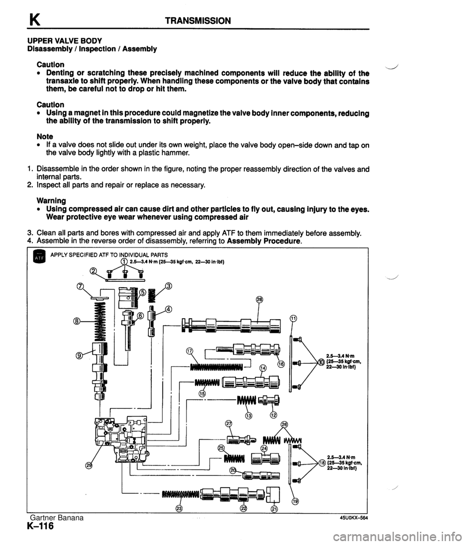
K TRANSMISSION UPPER VALVE BODY Disassembly / Inspection / Assembly Caution d Denting or scratching these precisely machined components will reduce the ability of the transaxle to shift properly. When handling these components or the valve body that contains them, be careful not to drop or hit them. Caution Using a magnet in this procedure could magnetize the valve body inner components, reducing the ability of the transmission to shift properly. Note If a valve does not slide out under its own weight, place the valve body open-side down and tap on the valve body lightly with a plastic hammer. 1. Disassemble in the order shown in the figure, noting the proper reassembly direction of the valves and internal parts. 2. Inspect all parts and repair or replace as necessary. Warning Using compressed air can cause dirt and other particles to fly out, causing injury to the eyes. Wear protective eye wear whenever using compressed air 3. Clean all parts and bores with compressed air and apply ATF to them immediately before assembly. 4. Assemble in the reverse order of disassembly, referring to Assembly Procedure. APPLY SPECIFIED ATF TO INDIVIDUAL PARTS Nvn (25--35 kgfwn, 22-30 Inlbf) Gartner Banana
Page 521 of 1708

K TRANSMISSION LOWER VALVE BODY Disassembly l Inspection l Assembly Caution d Denting or scratching these precisely machined components will reduce the ability of the transaxle to shift properly. When handling these components or the valve body that contains them, be careful not to drop or hit them. Caution Using a magnet in this procedure could magnetize the valve body inner components, reducing the ability of the transmission to shift properly. Note If a valve does not slide out under its own weight, place the valve body open-side down and tap on the valve body lightly with a plastic hammer. 1. Disassemble in the order shown in the figure, noting the proper reassembly direction of the valves and internal parts. 2. Inspect all parts and repair or replace as necessary. Warning Using compressed air can cause dirt and other particles to fly out, causing injury to the eyes. Wear protective eye wear whenever using compressed air. 3. Clean all parts and bores with compressed air and apply ATF to them immediately before assembly. 4. Assemble in the reverse order of disassembly, referring to Assembly Procedure. APPLY SPECIFIED ATF TO INDIVIDUAL PARTS B ?? "P 2.5-3.4 Nm {25-35 kgfcm, 22-30 in4bf) Gartner Banana