Page 1076 of 1708
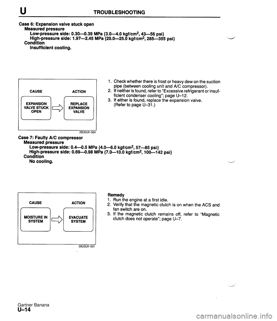
u TROUBLESHOOTING Case 6: Expansion valve stuck open Measured pressure Low-pressure side: 0.30-0.39 MPa {3.0-4.0 kgf/cm2, 43-56 psi) High-pressure side: 1.97-2.45 MPa (20.0-25.0 kgf/cm2, 285-355 psi) Condition Insufficient cooling. CAUSE ACTION 7 m EXPANSION REPLACE / VALWEiUCK I *I EXPANSION VALVE Case 7: Faulty AIC compressor Measured pressure 1. Check whether there is frost or heavy dew on the suction pipe (between cooling unit and AIC compressor). 2. If neither is found, refer to "Excessive refrigerant or insuf- ficient condenser cooling"; page U-12. 3. If either is found, replace the expansion valve. (Refer to page U-31.) LOW-pressure side: 0.4-0.5 MPa (4.0-6.0 kgf/cm2, 57-85 psi) High-pressure side: 0.69-0.98 MPa (7.0-10.0 kgflcm2, 100-1 42 psi) Condition No cooling. I 1 Remedy CAUSE ACTION MOISTURE IN 1. Run ihe engine at a first idle. 2. Verify that the magnetic clutch is on when the ACS and fan switch are on. 3. If the magnetic clutch remains off, refer to "Magnetic clutch does not operate"; page U-7. Gartner Banana
Page 1088 of 1708
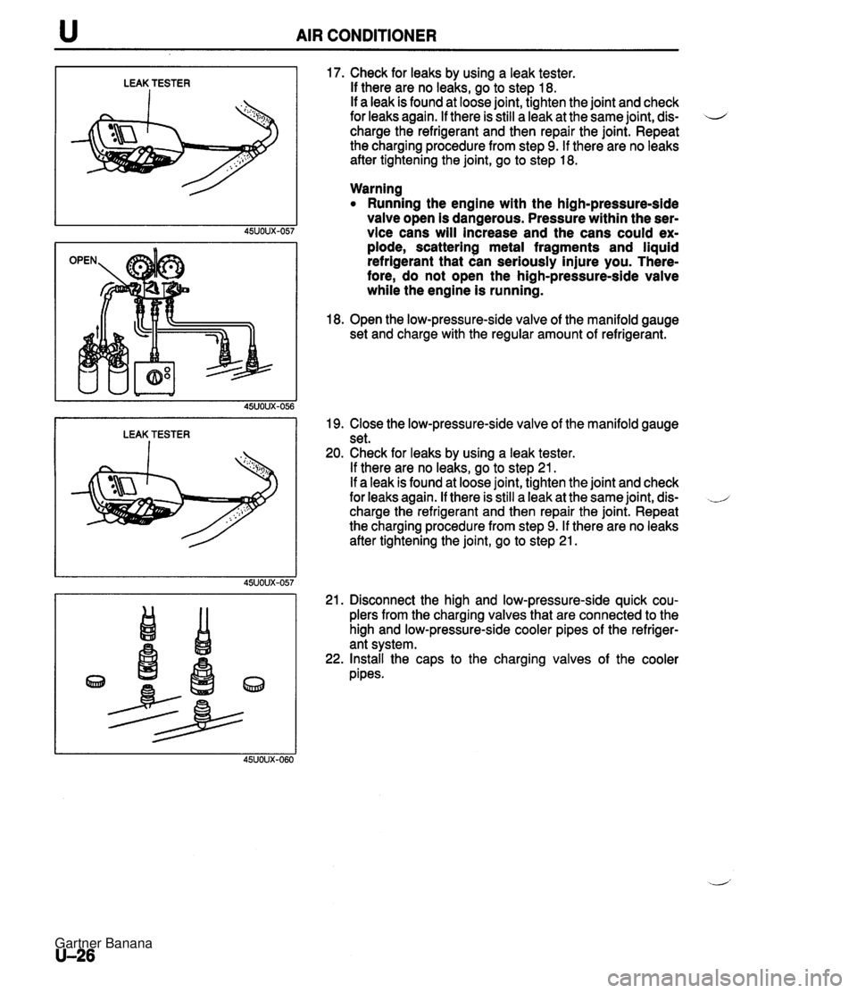
u AIR CONDITIONER LEAK TESTER I LEAK TESTER I 17. Check for leaks by using a leak tester. If there are no leaks, go to step 18. If a leak is found at loose joint, tighten the joint and check for leaks again. If there is still a leak at the same joint, dis- 4 charge the refrigerant and then repair the joint. Repeat the charging procedure from step 9. If there are no leaks after tightening the joint, go to step 18. Warning Running the engine with the high-pressure-side valve open is dangerous. Pressure within the ser- vice cans will increase and the cans could ex- plode, scattering metal fragments and liquid refrigerant that can seriously injure you. There- fore, do not open the high-pressure-side valve while the engine is running. 18. Open the low-pressure-side valve of the manifold gauge set and charge with the regular amount of refrigerant. 19. Close the low-pressure-side valve of the manifold gauge set. 20. Check for leaks by using a leak tester. If there are no leaks, go to step 21. If a leak is found at loose joint, tighten the joint and check for leaks again. If there is still a leak at the same joint, dis- charge the refrigerant and then repair the joint. Repeat the charging procedure from step 9. If there are no leaks after tightening the joint, go to step 21. 21. Disconnect the high and low-pressure-side quick cou- plers from the charging valves that are connected to the high and low-pressure-side cooler pipes of the refriger- ant system. 22. Install the caps to the charging valves of the cooler pipes. Gartner Banana
Page 1089 of 1708
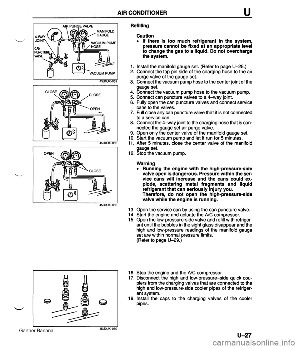
AIR CONDITIONER u Refilling Caution If there is too much refrigerant in the system, pressure cannot be fixed at an appropriate level to change the gas to a liquid. Do not overcharge the system. 1. Install the manifold gauge set. (Refer to page U-25.) 2. Connect the tap pin side of the charging hose to the air purge valve of the gauge set. 3. Connect the vacuum pump hose to the center joint of the gauge set. 4. Connect the vacuum pump hose to the vacuum pump. 5. Connect can puncture valves to a 4-way joint. 6. Fully open the can puncture valves and connect service cans to the valves. 7. Full close any can puncture valve that it is not connected to a service can. 8. Connect the 4-way joint to the charging hose that is con- nected the gauge set air purge valve. 9. Open only the center valve of the manifold gauge set. 10. Start the vacuum pump and let it run for 5 minutes. 11. After 5 minutes, close the center valve of the manifold gauge set. 12. Stop the vacuum pump. Warning Running the engine with the high-pressure-side valve open is dangerous. Pressure within the ser- vice cans will increase and the cans could ex- plode, scattering metal fragments and liquid refrigerant that can seriously injury you. Therefore, do not open the high-pressure-side valve while the engine is running. 13. Open the service can by using the can puncture valve. 14. Start the engine and actuate the A/C compressor. 15. Open the low-pressure-side valve and refill with refriger- ant until the bubbles in the sight glass disappear and the high and low-pressure readings of the manifold gauge set are within normal pressure limits. (Refer to page U-29.) 16. Stop the engine and the NC compressor. 17. Disconnect the high and low-pressure-side quick cou- plers from the charging valves that are connected to the high and low-pressure-side cooler pipes of the refriger- ant system. 18. Install the caps to the charging valves of the cooler pipes. 45UOUX-060 Gartner Banana
Page 1090 of 1708
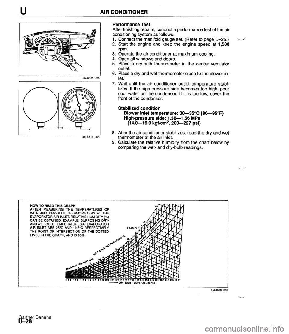
u AIR CONDITIONER Performance Test After finishing repairs, conduct a performance test of the air conditioning system as follows. 1. Connect the manifold gauge set. (Refer to page U-25.) 2. Start the engine and keep the engine speed at 1,500 rpm. 3. Operate the air conditioner at maximum cooling. 4. Open all windows and doors. 5. Place a dry-bulb thermometer in the center ventilator outlet. 6. Place a dry and wet thermometer close to the blower in- let. 7. Wait until the air conditioner outlet temperature stabi- lizes. If the high-pressure side becomes too high, pour cool water on the condenser. If it is too low, cover the front of the condenser. Stabilized condition Blower inlet temperature: 30-35°C (86-95°F) High-pressure side: 1.38-1.56 MPa (1 4.0-1 6.0 kgflcm*, 200-227 psi) 8. After the air conditioner stabilizes, read the dry and wet thermometer at the air inlet. 9. Calculate the relative humidity from the chart below by comparing the wet- and dry-bulb readings. Gartner Banana
Page 1091 of 1708
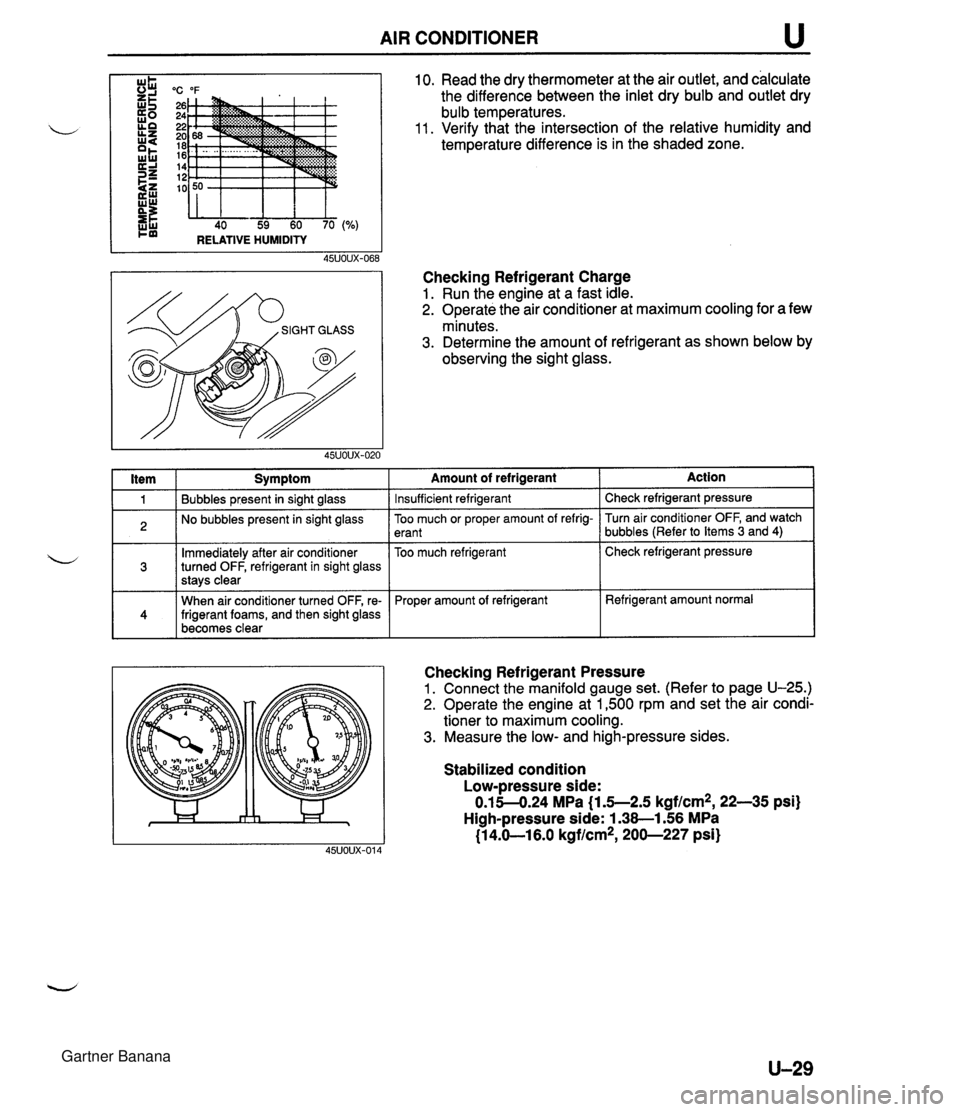
AIR CONDITIONER u "C "F 26 24 22 20 18 16 14 12 10 40 59 60 70 RELATIVE HUMIDITY I ltem I Symptom 10. Read the dry thermometer at the air outlet, and calculate the difference between the inlet dry bulb and outlet dry bulb temperatures. 11. Verify that the intersection of the relative humidity and temperature difference is in the shaded zone. Checking Refrigerant Charge 1. Run the engine at a fast idle. 2. Operate the air conditioner at maximum cooling for a few minutes. 3. Determine the amount of refrigerant as shown below by observing the sight glass. 1 Bubbles present in sight glass 2 No bubbles present in sight glass Immediately after air conditioner turned OFF, refrigerant in sight glass stavs clear 141 When air conditioner turned OFF, re- frigerant foams, and then sight glass becomes clear -- Amount of refrigerant Insufficient refrigerant Action Check refrigerant pressure -- Too much or proper amount of refrig- erant Too much refrigerant Checking Refrigerant Pressure 1. Connect the manifold gauge set. (Refer to page U-25.) 2. Operate the engine at 1,500 rpm and set the air condi- tioner to maximum cooling. 3. Measure the low- and high-pressure sides. Turn air conditioner OFF, and watch bubbles (Refer to Items 3 and 4) Check refrigerant pressure Proper amount of refrigerant Stabilized condition Low-pressure side: 0.15-4.24 MPa {I .5--2.5 kgf/cm2, 22-35 psi) High-pressure side: 1.38-1.56 MPa (1 4.61 6.0 kgflcm*, 200-227 psi) Refrigerant amount normal Gartner Banana
Page 1094 of 1708
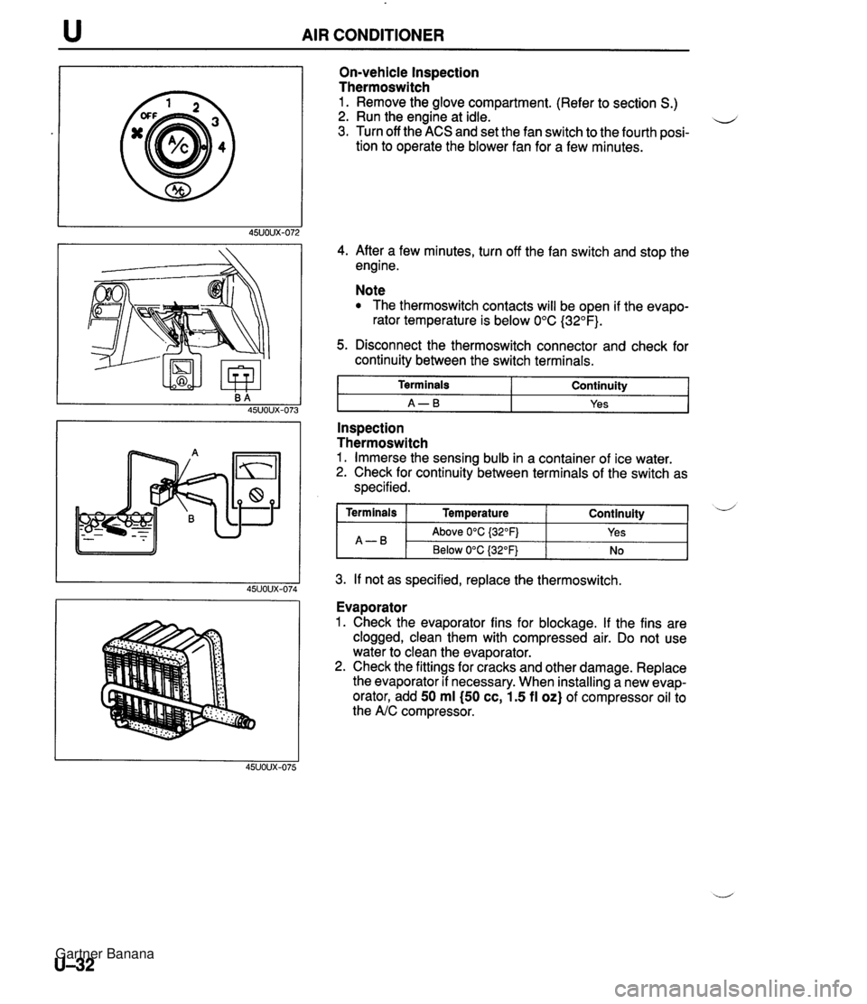
AIR CONDITIONER On-vehicle Inspection Thermoswitch 1. Remove the glove compartment. (Refer to section S.) 2. Run the engine at idle. u 3. Turn off the ACS and set the fan switch to the fourth posi- tion to operate the blower fan for a few minutes. 4. After a few minutes, turn off the fan switch and stop the engine. Note The thermoswitch contacts will be open if the evapo- rator temperature is below 0°C (32°F). 5. Disconnect the thermoswitch connector and check for continuity between the switch terminals. I Terminals I Continuity I I A-B I Yes I - -- Inspection Thermoswitch 1. Immerse the sensing bulb in a container of ice water. 2. Check for continuity between terminals of the switch as specified. 3. If not as specified, replace the thermoswitch. Continuity ( Terminals I Temperature A-B Evaporator 1. Check the evaporator fins for blockage. If the fins are clogged, clean them with compressed air. Do not use water to clean the evaporator. 2. Check the fittings for cracks and other damage. Replace the evaporator if necessary. When installing a new evap- orator, add 50 ml (50 cc, 1.5 fl oz) of compressor oil to the A/C compressor. d Above 0°C {32OFj Below 0°C (32°F) Yes No Gartner Banana
Page 1109 of 1708
TECHNICAL DATA MEASUREMENTS ......................... TD- 2 ................................... ENGINE TD- 2 .................... LUBRICATION SYSTEM TD- 5 ........................ COOLING SYSTEM TD- 5 FUEL AND EMISSION CONTROL SYSTEMS . TD- 6 ENGINE ELECTRICAL SYSTEM ............. TD- 7 .................................. CLUTCH TD- 7 .................. MANUAL TRANSMISSION TD- 8 AUTOMATIC TRANSMISSION ............... TD- 9 ....................... PROPELLER SHAFT TD-11 FRONT AND REAR AXLES ................. TD-12 STEERING SYSTEM ....................... TD-12 BRAKING SYSTEM ........................ TD-13 WHEELS AND TIRES ...................... TD-13 ............................. SUSPENSION TD-14 BODY ELECTRICAL SYSTEM ............... TD-15 HEATER AND AIR CONDITIONING SYSTEM . TD-15 STANDARD BOLT AND NUT TIGHTENING ................................. TORQUE TD-15 45UTDX-001 Gartner Banana
Page 1110 of 1708
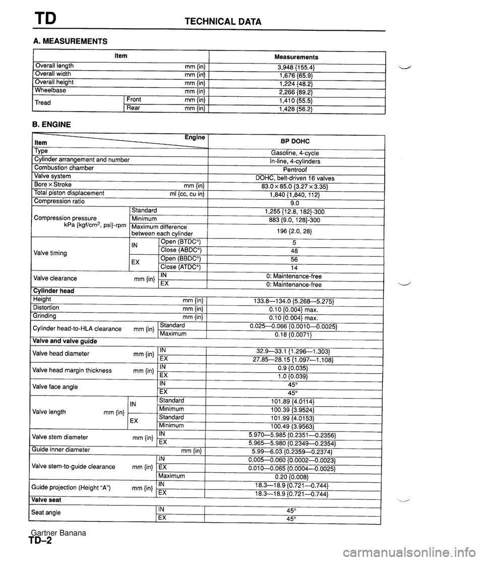
TD TECHNICAL DATA A. MEASUREMENTS I Item I Measurements I B. ENGINE Overall length mm {in) Overall width mm (in) Overall height mm {in) Wheelbase mm {in) 3,948 (1 55.4) 1,676 i65.9) 1,224 I48.2) 2,266 I89.2) 1,410 (55.5) 1,428 (56.2) Tread - ltem Tvoe u Front mm (in) Rear mm {in) BP DOHC Gasoline. 4-cvcle . In-line, 4-cylinders Pentroof DOHC, belt-driven 16 valves 83.0 x 85.0 {3.27 x 3.35) 1,840 (1,840, 11 2) 9.0 1,255 {I 2.8, 1823-300 883 (9.0, 1281-300 196 {2.0, 28) s. Cylinder arrangement and number Combustion chamber Valve system Bore x Stroke mm {in] Total piston displacement ml {cc, cu in) Compression ratio Valve timing Compression pressure kPa (kgflcm2. psil-r~m I Valve and valve auide I Standard Minimum Maximum difference between each cvlinder - - IN openz (BTDCO) Close (ABDCO) Open (BBDCO) EX close (ATDC") Valve clearance mm {in) Cylinder head 5 48 56 14 IN 133.8-1 34.0 i5.268-5.275) 0.1 0 {0.004) max. 0.10 {0.004) max. 0.02G0.066 {0.0010-0,0025) 0.18 {0.0071) Height mm (in) Distortion mm {in) Grinding mm {in) - 0: Maintenance-free Cylinder head-to-HLA clearance mm (in} Valve head diameter mm Iin) Valve head margin thickness mm {in} Valve face angle I Valve seat 1 u Standard Maximum Valve length mm {in) EX IN EX IN EX IN EX Standard Minimum Standard Minimum IN EX IN EX 5.99--6.03 iO.2359--0.2374) 0.005--0.060 (0.0002-0.0023) 0.01 b0.065 (0.0004-0,0025) 0.20 {0.008} 18.3-1 8.9 {0.7214.744) 18.3-1 8.9 (0.721-0.744) Guide inner diameter mm (in) 0: Maintenance-free 32.9-33.1 {I .296--1.303) 27.85-28.15 {I .097-1 .I 08) 0.9 {0.035) 1 .O (0.039) 45" 45" 101.89 {4.0114} 100.39 {3.9524) 101.99 (4.0153) 100.49 (3,9563) 5.970-5.985 {0.2351-0.2356) 5.96G5.980 l0.2349-0.2354) Valve stem diameter mm {in) Valve stem-to-guide clearance mm (in) Guide projection (Height "A) mm {in) Seat angle IN EX Maximum IN EX IN 45" EX 45" Gartner Banana