Page 144 of 1708
RADIATOR RADIATOR REMOVAL I INSTALLATION 1. Disconnect the negative battery cable. 2. Drain the engine coolant. (Refer to page E-5 for WARNING and procedure.) 3. Remove the undercover. 4. Remove in the order shown in the figure. 5. Install in the reverse order of removal. 1. Air intake pipe 5. Coolant fan, condenser fan 2. Radiator hose 6. Radiator 3. Coolant reservoir hose Inspection . . . . . . . . . . . . . . . . . . . . . . below 4. Coolant fan motor connector, condenser fan motor connector INSPECTION Check for the following and repair or replace as necessary. 1. Cracks, damage, and water leakage. 2. Bent fins (repair with a screwdriver). 3. Distorted or bent radiator inlet. Steps After Installation 1. Install the undercover. _i 2. Connect the negative battery cable. 3. Fill the radiator with coolant. (Refer to page E-6 for WARNING and procedure.) Gartner Banana
Page 145 of 1708
THERMOSTAT E THERMOSTAT REMOVAL / INSTALLATION u 1. Disconnect the negative battery cable. 2. Drain the engine coolant. (Refer to page E-5 for WARNING and procedure.) 3. Remove in the order shown in the figure. 4. Install in the reverse order of removal. @) REPLACE TAB MUST BE ASSEMBLED TOWARD THERMOSTAT COVER 1. Thermostat cover 3. Thermostat 2. Thermostat cover gasket Inspection . . . . . . . . . . . . . . . . . . . . . . below INSPECTION 1. Visually check that the thermostat valve is airtight. 2. Place the thermostat and a thermometer in water. 3. Heat the water and check the following: Initial-opening temperature Main: 86.5-89.S°C (1 88--193OF) Sub: 83.5--86.S°C (1 8Sl87OF) Full-open temperature: 100°C (21 2°F) Full-open lift Main: 8.0mm 10.31 in) min. Sub: 1.5mm (0.06 in) min. Steps After installation 1. Connect the negative battery cable. 2. Fill the radiator with coolant. (Refer to page €4 for WARNING and procedure.) u Gartner Banana
Page 147 of 1708
WATER PUMP Stens After Installation 1. connect the neaative batterv cable. Removal Note PIS oil pump 1. Remove the PIS oil pump with the hoses still connected. 2. Position the pump away from the water pump and affix it with wire. 2. Fill the radiator kith coolant: (Refer to page E-6 for WARNING and procedure.) Gartner Banana
Page 217 of 1708

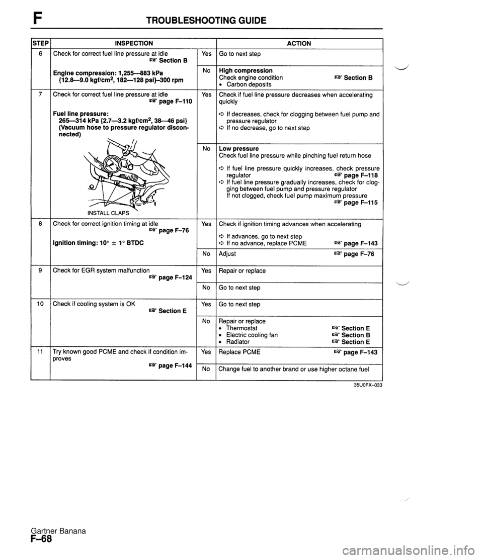
TROUBLESHOOTING GUIDE INSPECTION Check for correct fuel line pressure at idle Section B ACTION Go to next step - Yes High compression Check engine condition Carbon deposits Engine compression: 1,255-883 kPa 112.8-9.0 kgf/cm2, 182-128 psi)-300 rpm Section B Check for correct fuel line pressure at idle page F-110 Yes - No Check if fuel line pressure decreases when accelerating quickly Fuel line pressure: 265-314 kPa (2.7-43.2 kgf/cm2, 38-46 psi) (Vacuum hose to pressure regulator discon- nected) 0 If decreases, check for clogging between fuel pump and pressure regulator 0 If no decrease, go to next step Low pressure Check fuel line pressure while pinching fuel return hose 0 If fuel line pressure quickly increases, check pressure regulator page F-118 0 If fuel line pressure gradually increases, check for clog- ging between fuel pump and pressure regulator If not clogged, check fuel pump maximum pressure w page F-115 INSTALL CLAPS Check for correct ignition timing at idle IJ&T page F-76 Yes Check if ignition timing advances when accelerating o If advances, go to next step o If no advance, replace PCME LW page F-143 Ignition timing: 10" + lo BTDC No - Yes Adjust page F-76 Check for EGR system malfunction page F-124 Repair or replace Go to next step Go to next step Check if cooling system is OK Section E Yes No - Yes Repair or replace Thermostat Electric cooling fan Radiator ~3 Section E Section B Section E Try known good PCME and check if condition im- proves IJ&T page F-144 Replace PCME page F-143 Change fuel to another brand or use higher octane fuel Gartner Banana
Page 224 of 1708

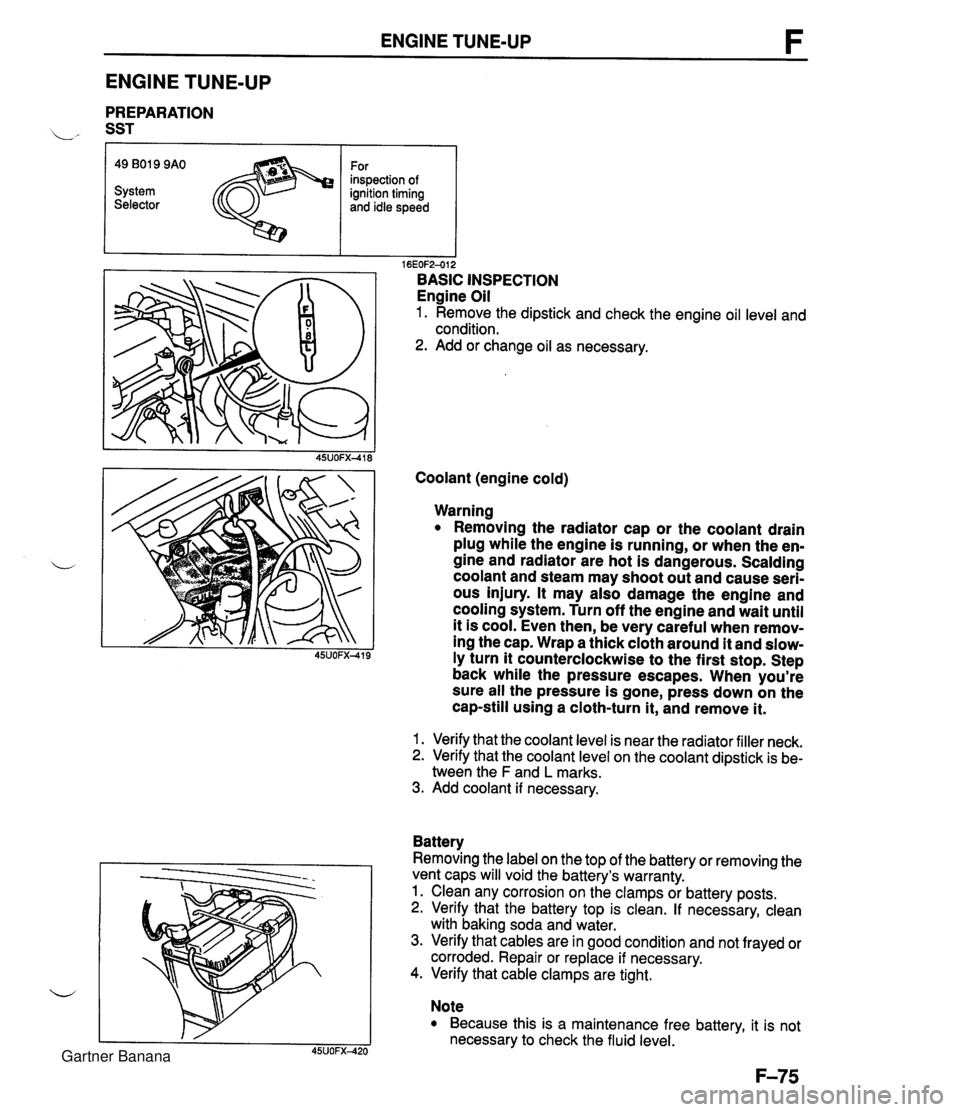
ENGINE TUNE-UP ENGINE TUNE-UP PREPARATION L" SST r I I 16EOF2-012 BASIC INSPECTION Engine Oil 1. Remove the dipstick and check the engine oil level and condition. 2. Add or change oil as necessary. 49 B019 9AO System Selector Coolant (engine cold) For inspection of ignition timing and idle speed Warning Removing the radiator cap or the coolant drain plug while the engine is running, or when the en- gine and radiator are hot is dangerous. Scalding coolant and steam may shoot out and cause seri- ous injury. It may also damage the engine and cooling system. Turn off the engine and wait until it is cool. Even then, be very careful when remov- ing the cap. Wrap a thick cloth around it and slow- ly turn it counterclockwise to the first stop. Step back while the pressure escapes. When you're sure all the pressure is gone, press down on the cap-still using a cloth-turn it, and remove it. 1. Verify that the coolant level is near the radiator filler neck. 2. Verify that the coolant level on the coolant dipstick is be- tween the F and L marks. 3. Add coolant if necessary. Battery Removing the label on the top of the battery or removing the vent caps will void the battery's warranty. 1. Clean any corrosion on the clamps or battery posts. 2. Verify that the battery top is clean. If necessary, clean with baking soda and water. 3. Verify that cables are in good condition and not frayed or corroded. Repair or replace if necessary. 4. Verify that cable clamps are tight. Note Because this is a maintenance free battery, it is not necessary to check the fluid level. Gartner Banana
Page 552 of 1708
OIL COOLER K OIL COOLER REMOVAL / INSPECTION / INSTALLATION 1. Remove in the order shown in the figure. 2. lnspect all parts and repair or replace as necessary. 3. Install in the reverse order of removal, referring to lnstallation Note. 45UOKX-57 1. Connector bolts 4. Oil pipe Inspect for clogging ins~ect for damaae or cracks -- - - 2. Packing installation Note ................ below 3. Transmission 5. Oil hose Removal ................. page K- 45 Inspect for damage or cracks Installation ............... page K-148 6. Radiator I UP SIDE DOWN SlDE lnstallation Note Oil pipe 1. Align the marks, and slide the oil cooler hose onto the oil cooler pipe until it contacts the ridge. 2. Install the hose clamp onto the hose at the center of the mark and at the angle shown. If reusing the hose, posi- tion the new hose clamp in the mark left by the previous hose clamp. 3. Verify that the hose clamp does not interfere with any other parts. Gartner Banana
Page 736 of 1708

OUTLINE OUTLINE SPECIFICATIONS Front Suspension - Transmission item (Stabilizer Specifications MT I AT - I Susoension tvoe I . , . , I . , Shock absorber Cylindrical double acting, low-pressure-gas charged I Double-wishbone TY pe Torsion bar Coil spring I - Diameter mm linl I 20.0 10.79) Identification mark color 19.0 (0.75) White Wire diameter mm (in) Coil inner diameter mm {in) I Blue Free length mm {in) Coil number 11 .O (0.43) 83 i3.27) 11 .O (0.43) 83 (3.27) 292.5 (1 1 32) 6.32 3 +. 3 (0.12 + 0.12) 0°18' + 18' Total toe-in I - I 35UORX-001 Rear Suspension 302.0 (1 1.89) 6.32 mm {in) degree Total toe-in (per side) 1 degree Front wheel alignment (Unladedt1) 0°09' +. 09' Caster anglee3 4"26' +. 45' Kingpin angle 11 "20' Maximum steering angle Transmission Specifications MT I AT Item Differential - Suspension type Inner Outer "TORSEN" LSD 1 Standard Double-wishbone Coil springs 370 23' a 2" 32" 32' -t 2" Camber anglee2 Torsion bar 12.0 (0.47) 1 11.0 (0.43) 1 11 .O (0.43) Cylindrical double acting, low-pressure-gas charged - Stabilizer Identification mark color Wire diameter mm {in) 0°24' + 45' Type Diameter mm {in) I Coil number I 7.68 I 7.96 I Shock absorber Yellow 10.1 {0.40} Coil inner diameter mm {in) Free length mm {in) Green 10.2 {0.40) 35UORX-002 *I Fuel tank full; radiator coolant and engine oil at specified levels; spare tire, jack, and tools in designated positions. '2 Difference between left and right must not exceed I O. '3 Difference between left and right must not exceed 1'30'. "TORSEN" is a registered trademark of ZEXEL-GLEASON USA.INC 83 I3.27) 348.5 j13.72) Rear wheel alignment (Unladed*') 83 (3.27) 356.5 (1 4.04) Total toe-in Total toe-in (per side) mm (in) degree degree 3 -c 3 (0.12 + 0.121 0°18' + 18' 0°09' + 09' Camber angle*2 -0°43' 2 30' Gartner Banana
Page 738 of 1708

WHEEL ALIGNMENT WHEEL ALIGNMENT FRONT WHEEL ALIGNMENT Specifications (Unladed*l) PRE-INSPECTION 1. Check the tire inflations, and adjust to the recommended d pressure if necessary. 2. lnspect the front wheel bearing play and correct if neces- sary. 3. lnspect the wheel and tire runouts. 4. Inspect the ball joints and steering linkage for excessive looseness. 5. The vehicle must be on level ground and carry no lug- gage or passengers. 6. Measure the height from the center of the wheel to the fender brim. The difference between left and right mea- surement must not exceed 10mm (0.39 in), and the rear measurement must be larger then the front measure- ment by 10-30mm (0.4--1.1 in). Caution The proper caster and camber angle vary depend- ing on the vehicle height. Refer to the following and to page R-9 for the specifications. Inspection and adjustment of wheel alignment must be done with the vehicle unladed*'. . . I Y -- t~otal toe-in l~er side) I 1 dearee 0'09' + 09' I Total toe-in 3 2 3 I0.12 2 0.12) 0'1 8' 2 18' mm (in) dearee Maximum steering angle U - Inner Outer 11 '20' -0°20' 2 45' 0'03' ? 45' 0'24' 2 45' 0°44' -+ 45' 1'02' -+ 45' 5'1 6' ? 45' 5O02' -+ 45' 4O49' 2 45' 4'35' -+ 45' 4'21 ' -+ 45' I Kingpin angle 37"23' -+ 2" 32O32' 2 2" '1 Fuel tank full; radiator coolant and engine oil at specified levels; spare tire, jack, and tools in designated positions. OSUORX-009 ** Difference between left and right must not exceed lo. '3 Difference between left and right must not exeed 1'30'. 328-337 {I 2.9-1 3.3) 338-347 {I 3.3-1 3.7) 340-357 I13.7-14.1) 358-367 {I 4.1-14.4) 36&377 {I 4.4--14.8) 328-337 {I 2.9--13.3) 338-347 {I 3.3-1 3.7) 348-357 113.7-14.1) 358-367 {I 4.1-14.4) 368-377 {I 4.4--14.8) Camber angleg2 Caster angle*3 Height from center Of wheel to fender brim mm {in) Height from center Of wheel to fender brim mm (in) Gartner Banana