1994 MAZDA MX-5 air conditioning
[x] Cancel search: air conditioningPage 285 of 1708

F A/C CUT-OFF CONTROL SYSTEM D B AIC RE LAY SYSTEM INSPECTION 1. Turn the ignition switch ON. 2. Turn the blower switch and air conditioning sensor ON. 3. Start the engine. d 4. Verify that the A/C stops for approx. 2 sec. after the en- gine start. 5. Rotate the throttle link to fully open position. 6. Verify that the A/C stops for approx. 5 sec. after the throttle link to fully open position. 7. If not specified, inspect as following. PCME 1Q terminal voltage A/C relay Throttle position sensor AIC RELAY Inspection 1. Remove the A/C relay. 2. Check the continuity between the terminals of the relay. 3. If not specified, replace the A/C relay. B+: Battery positive voltage Terminal A - B Apply B+ B+ not applied Terminal C - D Yes No Gartner Banana
Page 294 of 1708

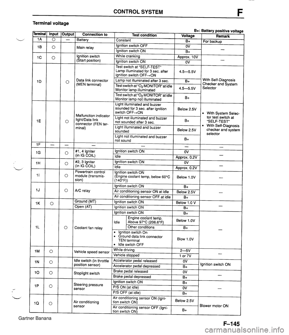
CONTROL SYSTEM F Terminal voltage B+: Battery positive voltage Test condition I Voltage I Remark - - - - - - - - - - - - - - - - - - Connection to Battery Constant Ignition switch OFF Main relay - B+ OV lgnition switch (Start position) For backup - Ignition switch ON While cranking Lamp illuminated for 3 sec. after 1 4.5-5.5V ianition switch OFF+ON 1 B+ Approx. 1 OV Ignition switch ON - - OV Data link connector (MEN terminal) Test switch at "SELF-TEST" .. Lamp not illuminated after 3 sec. Test switch at "02 MONITOR" at idle Monitor lam illuminated & 4.5-5.5v . . I Malfunction indicator IighVData link connector (FEN ter- minal) With Self-Diagnosis Checker and System Selector Test switch at "02 MONITOR" at idle Monitor lamp not illuminated Light illuminated and buzzer sounded for 3 sec. after ignition switch OFF-ON B+ tor tesiswitch at "SELF-TEST" With Self-Diagnosis checker and system selector Below 2.5V 1 Light illuminated and buzzer sounded 1 Below 2.5V I With System Selec- Light not illuminated and buzzer not sounded after 3 sec. I Light not illuminated and buzzer 1 n. 1 B+ not sound I D+ 1 - #I, 4 lgniter (in IG COIL) #2,3 Igniter (in IG COIL) Powertrain control module (transmis- sion) - Ignition switch ON Idle Ignition switch ON Idle lgnition switch ON (Engine coolant temp, below 60°C {I 40°F)) Ignition switch ON AtC relay Air conditioning sensor ON at idle Air conditioning sensor OFF at idle Ground (MT) - OV Approx. 0.2V OV Approx. 0.2V Below 1 .OV B+ Below 2.5V B+ - - - - , * Open (AT) - Ignition switch ON ( Below 1 .O V I Engine coolant temp. I Below .OV I ldle Above 97°C (206.6OF1 Ignition switch ON I I B+ Ignition switch ON Coolant fan relay B+ . - Other conditions lgnition switch On dround data link connector TEN terminal I Blow 1.0" I B+ Vehicle speed sensor ldle switch OFF While driving Vehicle sto~wed ldle switch (in throttle position sensor) 2-5V 1 or 7V . , Accelerator pedal released Accelerator ~edal de~ressed - Stoplight switch OV B+ Brake pedal released Brake ~edal deoressed lgnition switch ON Steering pressure sensor OV B+ I I - Ignition switch ON B+ - PIS ON (at idle) PIS OFF (at idle) Air conditioning sensor Air conditioning sensor ON (Igni- tion switch ON) Air conditioning sensor OFF (Igni- tion switch ON) OV B+ - Below 2.5V B+ Blower motor ON Gartner Banana
Page 297 of 1708

CONTROL SYSTEM Check Point for Each Terminal B+: Battery positive voltage Terminal -. - Connection to Abnormal voltage Possible cause Battery Always OV (Battery OK) Always OV Main relay a ROOM 10A fuse burned Open circuit in wiring from ROOM 1 OA fuse to PCME terminal 1A Main relay malfunction (Refer to page F-156) Open circuit in wiring from main relay to PCME termi- nal 1 B Ignition switch (Start position) a Main relay malfunction (Refer to page F-156) Open circuit in wiring from main relay to data link connector terminal +B Open or short circuit in wiring from data link connec- tor terminal MEN to PCME terminal 1 D Always OV (Starter turns) Always OV Open circuit in wiring from starter interlock switch to PCME terminal 1 C Self-Diagnosis Checker (Monitor lamp) Always B+ a Poor connection at PCME connector PCME malfunction I Always approx. 5V I a PCME malfunction Malfunction indicator light (MIL) Always below 2.5V (MIL always ON) Always below 2.5V Open circuit in wiring from combination meter to (MIL never ON) I PCME terminal I E a Short circuit in wiring from combination meter to PCME terminal 1 E PCME malfunction Always B+ Poor connection at PCME connector a PCME malfunction Self-Diagnosis Checker (Code No.) Always below 2.5V (No display on Self-Diagnosis Checker) Main relay malfunction (Refer to page F-156) a Open circuit in wiring from main relay to data link connector terminal +B Always B+ Always below 2.5V ("88" is displayed and buzzer sounds continuously) a Poor connection at PCME connector a PCME malfunction - Open or short circuit in wiring from data link connec- tor terminal FEN to PCME terminal I E Igniter Always OV a Refer to Code No.01 troubleshooting I (Refer to section GI Powertrain control module (transmission) Always B+ I PCME malfunction A/C relay malfunction (Refer to section U) a Open circuit in wiring from main relay to NC relay a Open circuit in wiring from NC relay to PCME termi- nal 1 J a Short circuit in wiring from NC relay to PCME termi- nal 1 J a PCME malfunction Always below 2.5V (NC does not operate) Always below 2.5V (Air conditioning sensor OFF but A/C operates) AIC relay Air conditioning sensor malfunction (Refer to section U) Poor connection at PCME connector PCME malfunction Always B+ Open circuit in wiring from PCME terminal 1 K to ground PCME malfunction Ground (MT) Always B+ Open (AT) Always OV Short circuit in wiring from PCME terminal 1 K to grounc PCME malfunction Coolant fan relay Always below 1 .OV (Coolant fan OK) Open or short circuit in wiring from fan relay to PCME terminal I L PCME malfunction Gartner Banana
Page 298 of 1708

CONTROL SYSTEM B+: Battery positive voltage Terminal 1 M 7 1 N 10 1 P 1 Q 1 R 1 S 1 T 1 U Connection to Abnormal voltage Always approx. 1 V Always approx. 7V Possible cause r Vehicle speed sensor malfunction r Short circuit in wiring from vehicle speed sensor to PCME terminal 1 M Vehicle speed sensor - r Vehicle speed senso~malfunction r Open circuit in wiring from vehicle speed sensor to PCME terminal 1 M r Throttle position sensor misadjustment (Refer to page F-154) r Short circuit in wiring from PCME terminal 1 N to throttle position sensor 6 PCME malfunction Always OV Throttle position sensor (idle terminal) Always B+ r Throttle position sensor misadjustment (Refer to page F-154) r Open circuit in wiring from PCME terminal 1 N to throttle position sensor r Open circuit in wiring from throttle position sensor to ground Stoplight switch Always OV (Stoplights OK) r Open circuit in wiring from stoplight switch to PCME terminal 10 r Steering pressure sensor malfunction (Refer to page F-158) Short circuit in wiring from PCME terminal 1 P to steering pressure sensor r PCME malfunction r Steering pressure sensor malfunction (Refer to F-158) r Open circuit in wiring from PCME terminal 1 P to steering pressure sensor Open circuit in wiring from steering pressure sensor to ground r Air conditioning sensor malfunction (Refer to section U) r Short circuit in wiring from PCME terminal 1 Q to air conditioning sensor r Poor connection at PCME connector r PCME malfunction Always OV Steering pressure sensor Always B+ -- Air conditioning sensor Always OV (with blower switch ON) Air conditioning sensor malfunction (Refer to section U) Open circuit in wiring from PCME terminal 1Q to air conditioning sensor Open circuit in wiring from air conditioning sensor to blower switch Always B+ (with blower switch ON) (Blower fan OK) EGR solenoid valve (vent) Always OV r Refer to Code No.29 Troubleshooting (Refer to page F-92) Short circuit in wiring from blower switch to PCME terminal 1 S r Poor connection at PCME connector PCME malfunction Always OV (Blower fan OK) Blower switch Always B+ (Blower fan OK) Open circuit in wiring from blower switch to PCME terminal IS EGR solenoid (vacu- um) Always OV r Refer to Code No.28 Troubleshooting (Refer to paae F-92) Headlight switch Always OV (Headlights OK) r Open or short circuit in wiring from headlight relay to PCME terminal 1 U Gartner Banana
Page 1090 of 1708

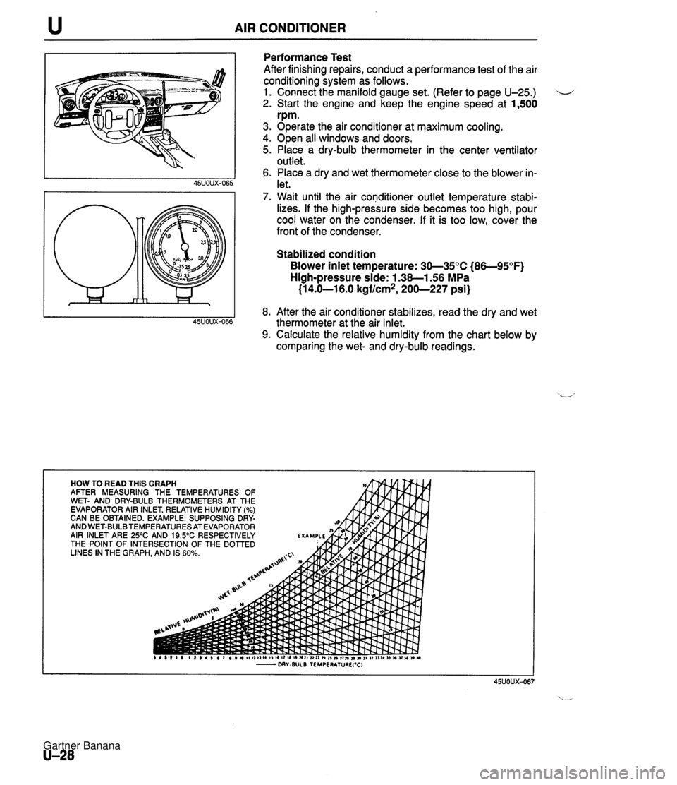
u AIR CONDITIONER Performance Test After finishing repairs, conduct a performance test of the air conditioning system as follows. 1. Connect the manifold gauge set. (Refer to page U-25.) 2. Start the engine and keep the engine speed at 1,500 rpm. 3. Operate the air conditioner at maximum cooling. 4. Open all windows and doors. 5. Place a dry-bulb thermometer in the center ventilator outlet. 6. Place a dry and wet thermometer close to the blower in- let. 7. Wait until the air conditioner outlet temperature stabi- lizes. If the high-pressure side becomes too high, pour cool water on the condenser. If it is too low, cover the front of the condenser. Stabilized condition Blower inlet temperature: 30-35°C (86-95°F) High-pressure side: 1.38-1.56 MPa (1 4.0-1 6.0 kgflcm*, 200-227 psi) 8. After the air conditioner stabilizes, read the dry and wet thermometer at the air inlet. 9. Calculate the relative humidity from the chart below by comparing the wet- and dry-bulb readings. Gartner Banana
Page 1109 of 1708

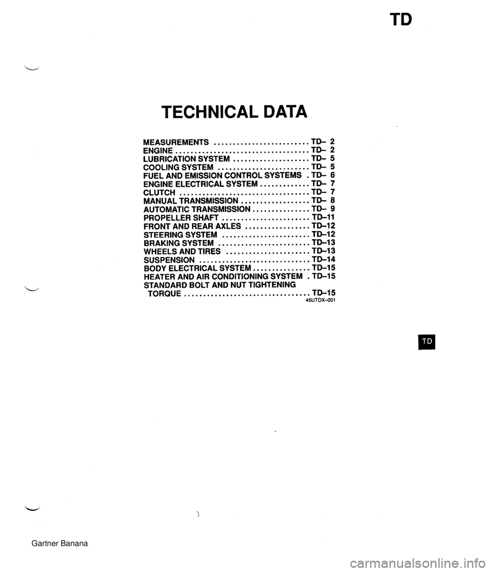
TECHNICAL DATA MEASUREMENTS ......................... TD- 2 ................................... ENGINE TD- 2 .................... LUBRICATION SYSTEM TD- 5 ........................ COOLING SYSTEM TD- 5 FUEL AND EMISSION CONTROL SYSTEMS . TD- 6 ENGINE ELECTRICAL SYSTEM ............. TD- 7 .................................. CLUTCH TD- 7 .................. MANUAL TRANSMISSION TD- 8 AUTOMATIC TRANSMISSION ............... TD- 9 ....................... PROPELLER SHAFT TD-11 FRONT AND REAR AXLES ................. TD-12 STEERING SYSTEM ....................... TD-12 BRAKING SYSTEM ........................ TD-13 WHEELS AND TIRES ...................... TD-13 ............................. SUSPENSION TD-14 BODY ELECTRICAL SYSTEM ............... TD-15 HEATER AND AIR CONDITIONING SYSTEM . TD-15 STANDARD BOLT AND NUT TIGHTENING ................................. TORQUE TD-15 45UTDX-001 Gartner Banana
Page 1123 of 1708

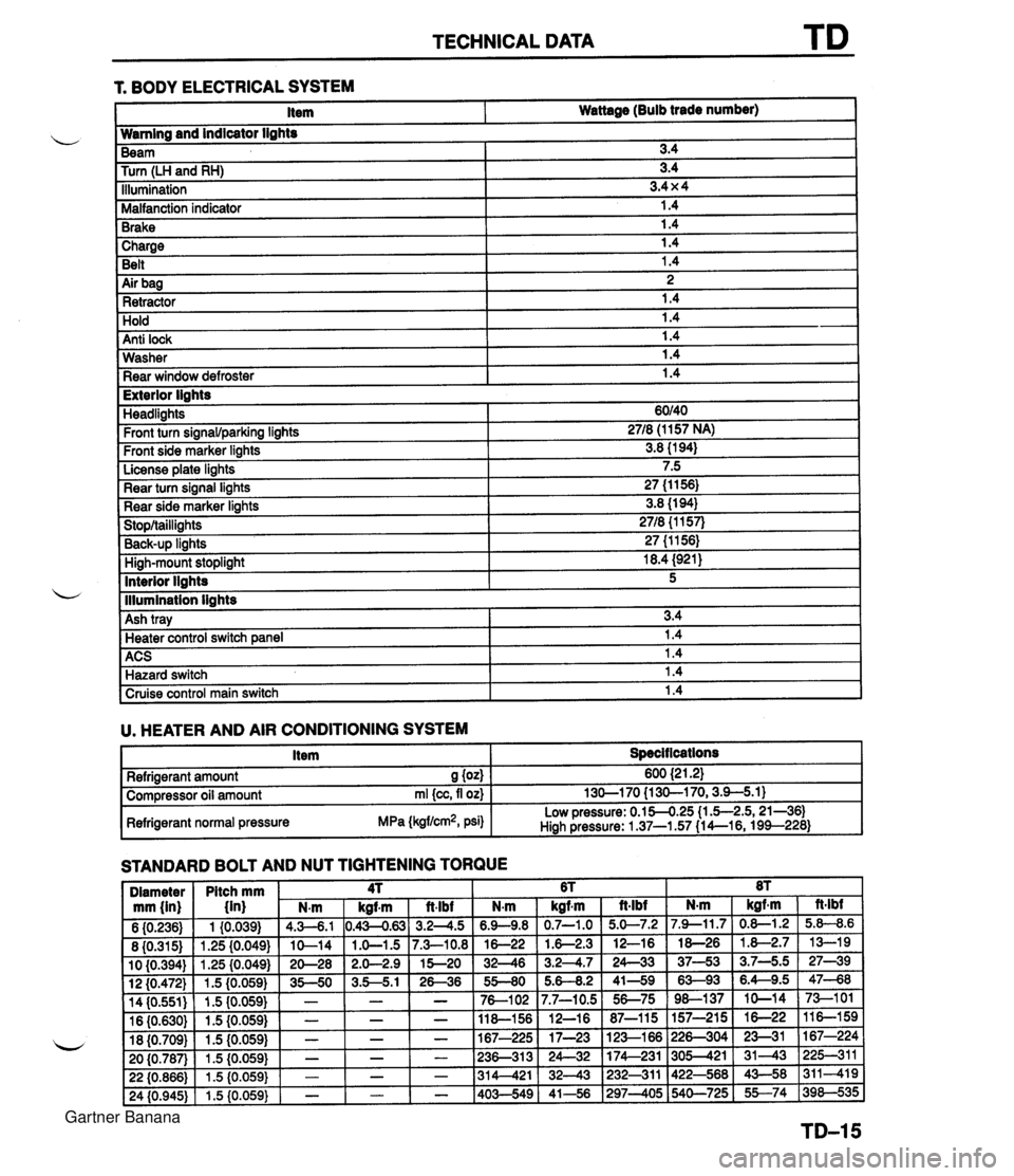
TECHNICAL DATA 1 Charge I 1.4 Belt 1.4 r. BODY ELECTRICAL SYSTEM 1 Air bag I 2 1 Retractor 1.4 Item Wattage (Bulb trade number) Hold Anti lock Wamlng and indicator lights 1.4 1.4 Washer Rear window defroster Beam Turn (LH and RH) Illumination Malfanction indicator Brake 1.4 1.4 I Exterior lights 3.4 3.4 3.4 x 4 1.4 1.4 Headlights Front turn signawparking lights Front side marker lights License plate lights Rear turn signal lights Rear side marker lights Stop/taillights Back-UP linhts High-mount stoplight I 18.4 (921) ACS 1 1.4 Hazard switch 1.4 60140 2718 (1 157 NA) 3.8 (1 94) 7.5 27 (1 1 56) 3.8 (1 94) 2718 {I 157) 27 (1 1561 Interior llahts - I lllumination lights I Cruise control main switch I 1.4 I 5 Ash tray U. HEATER AND AIR CONDITIONING SYSTEM I Item I Specit lcations I 3.4 Heater control switch ane el I 1.4 STANDARD BOLT AND NUT TIGHTENING TORQUE Refrigerant amount S (04 Compressor oil amount rnl {cc, fl oz) Refrigerant normal pressure MPa (kgflcm2, psi) 600 {2 1.21 130-1 70 {I 30-1 70,3.9-5.1) Low pressure: 0.154.25 (1 .5-2.5,21-361 Hiah Pressure: 1 37-1.57 (1 4--16, 199--228) Gartner Banana