Page 1031 of 1708
T SRS AIR BAG SYSTEM Possible cause e Damaged diagnostic module Remedy Replace the diagnostic module. (Refer to page T-208) Service Code 53 Flowchart No.18 I Flowchart N0.19 I Symptom ( Service Code 99 Symptom Possible cause Poor connection of all D-sensor and S-sensor Remedy Connect all D-sensor and S-sensor connectors. Gartner Banana
Page 1035 of 1708

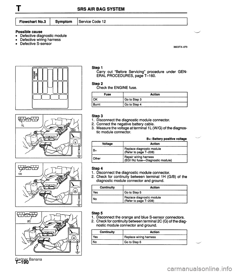
T SRS AIR BAG SYSTEM Possible cause ij Defective diagnostic module Defective wiring harness Defective S-sensor Step 1 Carry out "Before Servicing" procedure under GEN- ERAL PROCEDURES, page T-1 60. Service Code 12 Flowchart No.3 Step 2 Check the ENGINE fuse. Fuse Action I Symptom Step 3 1. Disconnect the diagnostic module connector. 2. Connect the negative battery cable. 3. Measure the voltage at terminal 1 L (WIG) of the diagnos- OK Burnt tic module connector. Go to Step 3 Go to Step 4 B+: Battery positive voltage - Other Repair wiring harness iEGI INJ fuss-Diaanostic module1 I Voltage B+ -- ~ Action Replace diagnostic module (Refer to page T-208) I NO Replace diagnostic module (Refer to Daae T-2081 Step 4 1. Disconnect the diagnostic module connector. 2. Check for continuity between terminal 1 H (GIB) of the diagnostic module connector and ground. Step 5 1. Disconnect the orange and blue S-sensor connectors. 2. Check for continuity between terminal 2C (G) of the diag- nostic module connector and ground. 1 Continuity Action 1 Continuity Yes Action Go to Step 5 Yes No Replace wiring harness Go to Step 6 L Gartner Banana
Page 1036 of 1708
SRS AIR BAG SYSTEM Step 6 Check for continuity between terminal 1H (G/B) of the diagnostic module connector and ground. I Flowchart No.4 I Symptom I Service Code 21 I Continuity Yes I No I Replace S-sensor (Refer to page T-213) I Action Replace air bag wiring harness and EGI INJ fuse Possible cause Defective S-sensor Defective wiring harness Defective diagnostic module Step 1 Carry out "Before Servicing" procedure under GEN- ERAL PROCEDURES, page T-1 60. Step 2 1. Disconnect the diagnostic module connector. 2. Check for continuity between terminal 1 E (RIB) of the diagnostic module connector and ground. I Continuitv Action 1 Yes Replace diagnostic module (Refer to page T-208) I NO I GO to step 3 Step 3 1. Disconnect the orange and blue S-sensor connectors. 2. Check for continuity between terminal A of the S-sensor and ground. Continuity 1 Action I 1 yes I Replace wiring harness I I No I Replace S-sensor (Refer to page T-213) I Gartner Banana
Page 1037 of 1708
T SRS AIR BAG SYSTEM Possible cause Defective diagnostic module Defective S-sensor Defective wiring harness Step 1 Carry out "Before Servicing" procedure under GEN- ERAL PROCEDURES, page T-1 60. Step 2 1. Disconnect the diagnostic module connector. 2. Check for continuity between terminal 1 H (GIB) or 2C (G) and terminal 28 (GNV) or 2D (GNV) of the diagnostic module connector. Step 3 1. Disconnect the orange and blue S-sensor connectors. 2. Check for continuity between termional B or E and termi- nal C or D of the S-sensor connector. Continuity Yes No I Continuity Action I Action Replace diagnostic module (Refer to page T-208) Go to Step 3 1 Yes I Replace S-sensor (Refer to page T-213) I I I NO I Replace wiring harness I Gartner Banana
Page 1038 of 1708
SRS AIR BAG SYSTEM T Possible cause Defective S-sensor Defective wiring harness Defective diagnostic module Flowchart No.6 Step 1 Carry out "Before Servicing" procedure under GEN- ERAL PROCEDURES, page T-1 60. Step 2 1. Disconnect the diagnostic module connector. 2. Check for continuity between terminals 2C (G) and 1 H (G/B) of the diagnostic module connector. I Continuity I Action I Symptom Service Code 23 Step 3 1. Disconnect the orange and blue S-sensor connectors. 2. Check for continuity between terminals E and B of the S-sensor. Yes No Replace diagnostic module (Refer to page T-208) Go to Step 3 I No I Replace S-sensor (Refer to ~aae T-213) I Continuity Yes Action Replace wiring harness Gartner Banana
Page 1042 of 1708

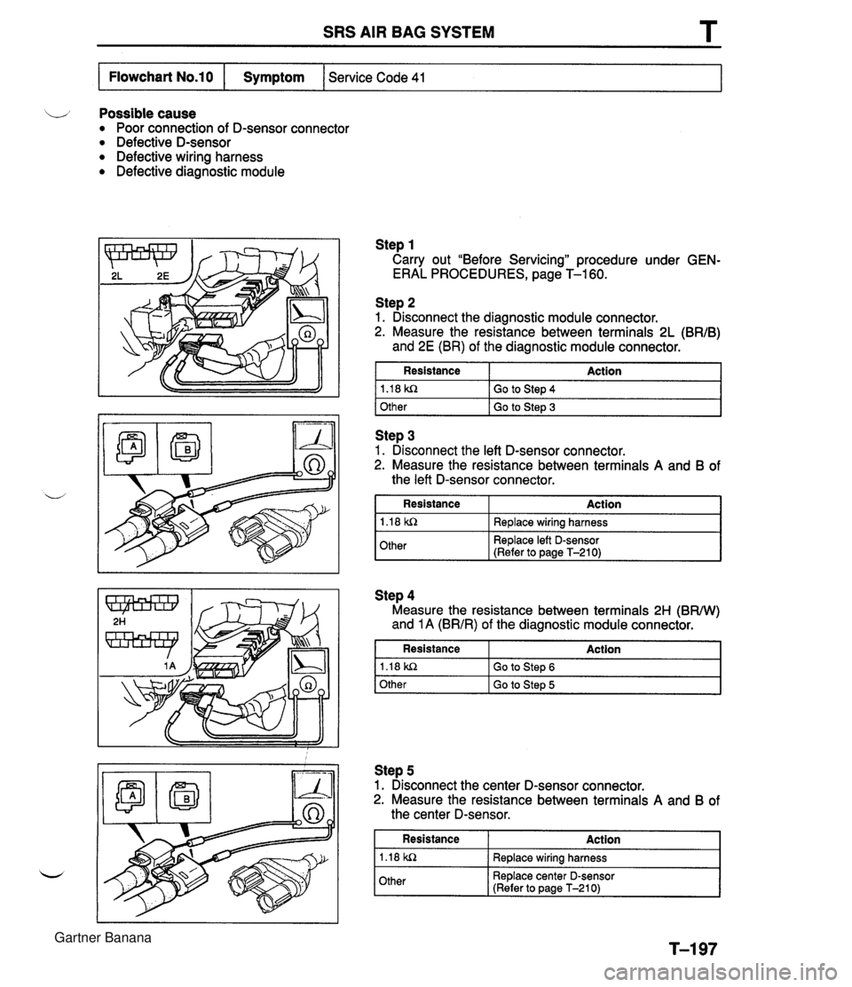
SRS AIR BAG SYSTEM T LJ Possible cause Poor connection of D-sensor connector Defective D-sensor Defective wiring harness Defective diagnostic module Flowchart No.10 Step 1 Carry out "Before Servicing" procedure under GEN- ERAL PROCEDURES, page T-1 60. Step 2 1. Disconnect the diagnostic module connector, 2. Measure the resistance between terminals 2L (BR/B) and 2E (BR) of the diagnostic module connector. Symptom Service Code 41 1 Other I Go to Ste~ 3 I Resistance 1.18 kn Action Go to Step 4 11.18 kn I I Redace wirina harness I Step 3 1. Disconnect the left D-sensor connector. 2. Measure the resistance between terminals A and B of the left D-sensor connector. Resistance Step 4 Measure the resistance between terminals 2H (BW) and 1 A (BR/R) of the diagnostic module connector. Action I Other I Resistance Action I Replace left 0-sensor (Refer to page T-210) 1.18 kn Other Go to Step 6 Go to Step 5 Step 5 1. Disconnect the center D-sensor connector. 2. Measure the resistance between terminals A and B of the center D-sensor. Resistance 1.18 kn Other Action Replace wiring harness Replace center D-sensor (Refer to page T-210) T-197 Gartner Banana
Page 1043 of 1708
T SRS AIR BAG SYSTEM Step 6 Measure the resistance between terminals 2J (BRN) and 1 C (BRIG) of the diagnostic module connector. I Resistance I Action I - Step 7 1. Disconnect the right D-sensor connector. 2. Measure the resistance between terminals A and B of 1.18 kR Other the right-D-sensor. Replace diagnostic module (Refer to page T-208) Go to Step 7 Resistance 1.18 WZ Action Replace wiring harness Other Replace right D-sensor (Refer to page T-210) Gartner Banana
Page 1044 of 1708
SRS AIR BAG SYSTEM T L Possible cause Poor installation of right D-sensor Defective right D-sensor Defective wiring harness Defective diagnostic module Step 1 Carry out "Before Servicing" procedure under GEN- ERAL PROCEDURES, page T-1 60. Service Code 44 Flowchart No.11 Symptom Step 3 1. Disconnect the right D-sensor connector. 2. Check for continuity between terminal B of the right D-sensor and ground. I Continuity I Action Step 2 1. Disconnect the diagnostic module connector. 2. Check for continuity between terminal 2J (BRN) of the diagnostic module connector and ground. 1 Yes I Replace wiring harness Continuity Yes No Action Replace diagnostic module (Refer to page T-208) Go to Step 3 No Replace right D-sensor (Refer to page T-210) Gartner Banana