Page 1066 of 1708
Ix-ozl MAIN FUSE eLOCK MAIN AD FAN IX-071 L/Y (€1 \ G-01 G -01 FRONT (F) -A/C IAC) G-02 MAGNETIC CLUTCH (F) G-03 BLOHER WIT (F) 16-04 ?$WER&TVRE SNITCt .CONDENSOR FAN .HEATER AND AIR CONDITIONER I I '07 CONENSOR FAN (AC) G-08 REFRIGERANT PflESSURE SWITCH (AC) IG-09 A/C RELAY (ACI 16- 10 COMENSER FAN RELAY (AC) Gartner Banana
Page 1067 of 1708
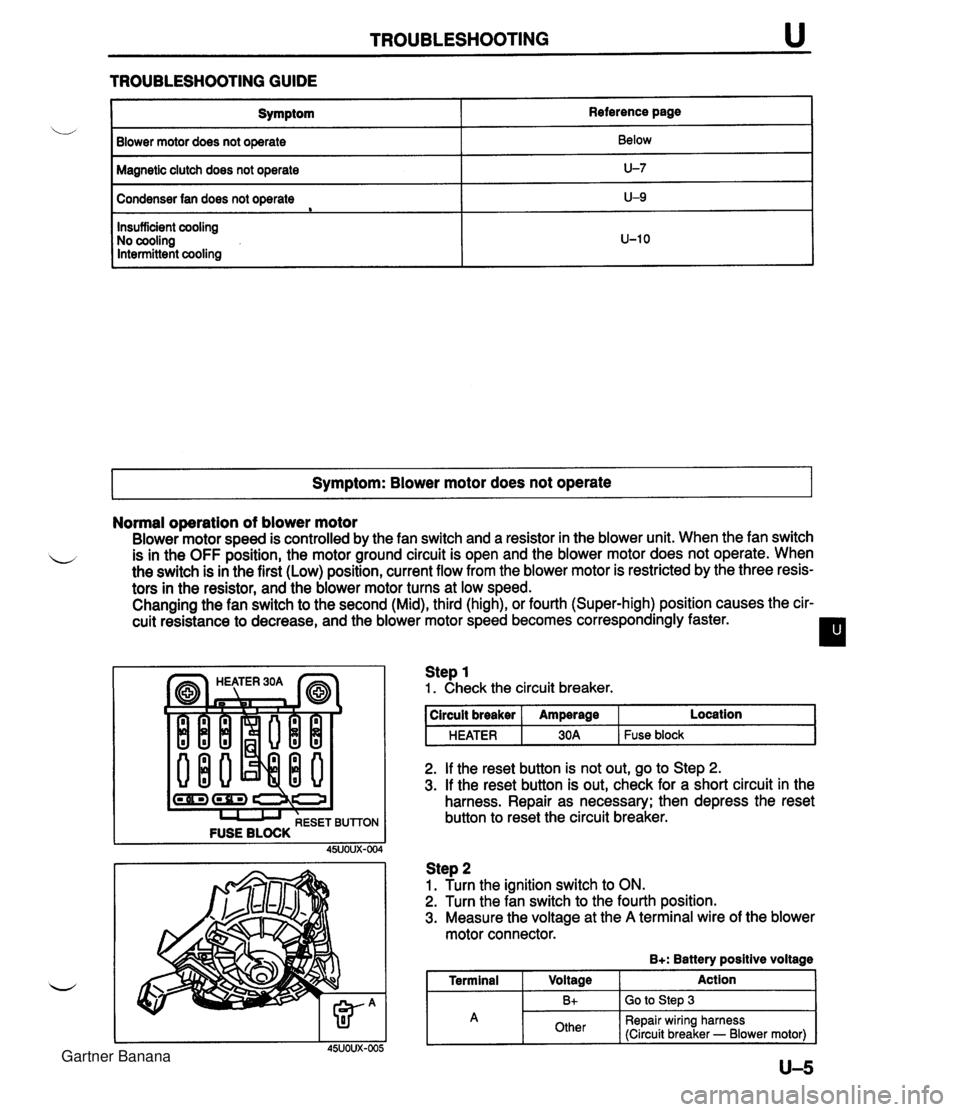
TROUBLESHOOTING u TROUBLESHOOTING GUIDE I Symptom Blower motor does not operate Reference page Below Magnetic clutch does not operate I U-7 Condenser fan does not operate e Symptom: Blower motor does not operate I U-9 Insufficient cooling No cooling Intermittent cooling Normal operation of blower motor Blower motor speed is controlled by the fan switch and a resistor in the blower unit. When the fan switch L is in the OFF position, the motor ground circuit is open and the blower motor does not operate. When the switch is in the first (Low) position, current flow from the blower motor is restricted by the three resis- tors in the resistor, and the blower motor turns at low speed. Changing the fan switch to the second (Mid), third (high), or fourth (Super-high) position causes the cir- cuit resistance to decrease, and the blower motor speed becomes correspondingly faster. I l U-10 (-1 (rn) I I I RESET BUTTON FUSE BLOCK Step 1 1. Check the circuit breaker. 2. If the reset button is not out, go to Step 2. 3. If the reset button is out, check for a short circuit in the harness. Repair as necessary; then depress the reset button to reset the circuit breaker. circuit breaker HEATER Step 2 1. Turn the ignition switch to ON. 2. Turn the fan switch to the fourth position. 3. Measure the voltage at the A terminal wire of the blower motor connector. B+: Battery positive voltage I Terminal I Voltage Action I Amperage 30A Location Fuse block A U-5 Bt Other Go to Step 3 Repair wiring harness (Circuit breaker - Blower motor) Gartner Banana
Page 1069 of 1708
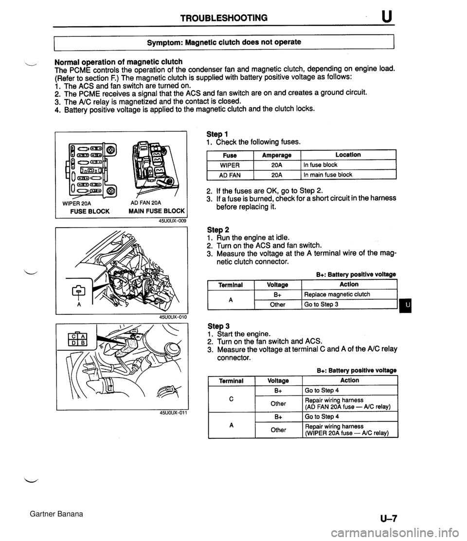
TROUBLESHOOTING u 7- Symptom: Magnetic clutch does not operate I Normal operation of magnetic clutch The PCME controls the operation of the condenser fan and magnetic clutch, depending on engine load. (Refer to section F.) The magnetic clutch is supplied with battery positive voltage as follows: 1. The ACS and fan switch are turned on. 2. The PCME receives a signal that the ACS and fan switch are on and creates a ground circuit. 3. The A/C relay is magnetized and the contact is closed. 4. Battery positive voltage is applied to the magnetic clutch and the clutch locks. WIPER 20A AD FAN 20A FUSE BLOCK MAIN FUSE BLOCK Step 1 1. Check the following fuses. I Fuse I Amperage I Location I I I . - I WIPER I 20A 1 In fuse block I I AD FAN I 20A 1 In main fuse block I 2. If the fuses are OK, go to Step 2. 3. If a fuse is burned, check for a short circuit in the harness before replacing it. Step 2 1. Run the engine at idle. 2. Turn on the ACS and fan switch. 3. Measure the voltage at the A terminal wire of the mag- netic clutch connector. B+: Battery positive voltage I Terminal I Voltage I Action 1 Step 3 1. Start the engine. 2. Turn on the fan switch and ACS. 3. Measure the voltage at terminal C and A of the A/C relay connector. B+: Batterv positive voltaae - -- A 1 Terminal I V0lta0e 1 Action I I C I Other I Repair wiring harness (AD FAN 20A fuse - AIC relay) I B+ Other I 1. -. B+ I GO to step 4 Replace magnetic clutch Go to Step 3 I A 1 Other I Repair wiring harness (WIPER 20A fuse - AIC relay) I Gartner Banana
Page 1070 of 1708
u TROUBLESHOOTING Step 4 1. Remove the relay. 2. Apply battery positive voltage and check for continuity between the relay terminals. B+: Battery positive voltage 0---0 : Continuity I I I 45U0UX-013 3. If correct, repair wiring harness (AC relay - magnetic clutch). 4. If not as specified, replace the A/C relay. 1 0 10 I I I 2 1 B+ 1 GND 1 0 I Gartner Banana
Page 1071 of 1708
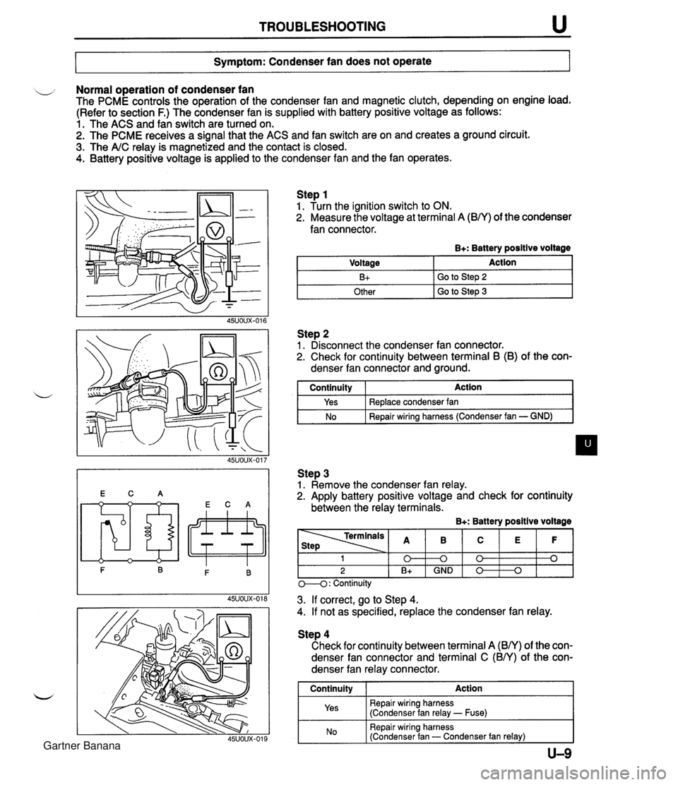
TROUBLESHOOTING u Symptom: Condenser fan does not operate Normal operation of condenser fan The PCME controls the operation of the condenser fan and magnetic clutch, depending on engine load. (Refer to section F.) The condenser fan is supplied with battery positive voltage as follows: 1. The ACS and fan switch are turned on. 2. The PCME receives a signal that the ACS and fan switch are on and creates a ground circuit. 3. The A/C relay is magnetized and the contact is closed. 4. Battery positive voltage is applied to the condenser fan and the fan operates. Step 1 1. Turn the ignition switch to ON. 2. Measure the voltage at terminal A (B/Y) of the condenser fan connector. B+: Battery positive voltage Step 2 1. Disconnect the condenser fan connector. 2. Check for continuity between terminal B (B) of the con- denser fan connector and ground. Voltage B+ Other I GO to step 3 Action Go to Step 2 I continuity I Action I Step 3 1. Remove the condenser fan relay. 2. Apply battery positive voltage and check for continuity between the relay terminals. B+: Battery positive voltage Yes No Replace condenser fan Repair wiring harness (Condenser fan - GND) M: Continuity - - - 3. If correct, go to Step 4. 4. If not as specified, replace the condenser fan relay. 1 0 2 B+ Step 4 Check for continuity between terminal A (BN) of the con- denser fan connector and terminal C (BN) of the con- denser fan relay connector. I Continuity I Action 1 Repair wiring harness (Condenser fan relay - Fuse) B 0 GND I Repair wiring harness (Condenser fan - Condenser fan relay) I C 0 0 E 0 F 0 Gartner Banana
Page 1076 of 1708
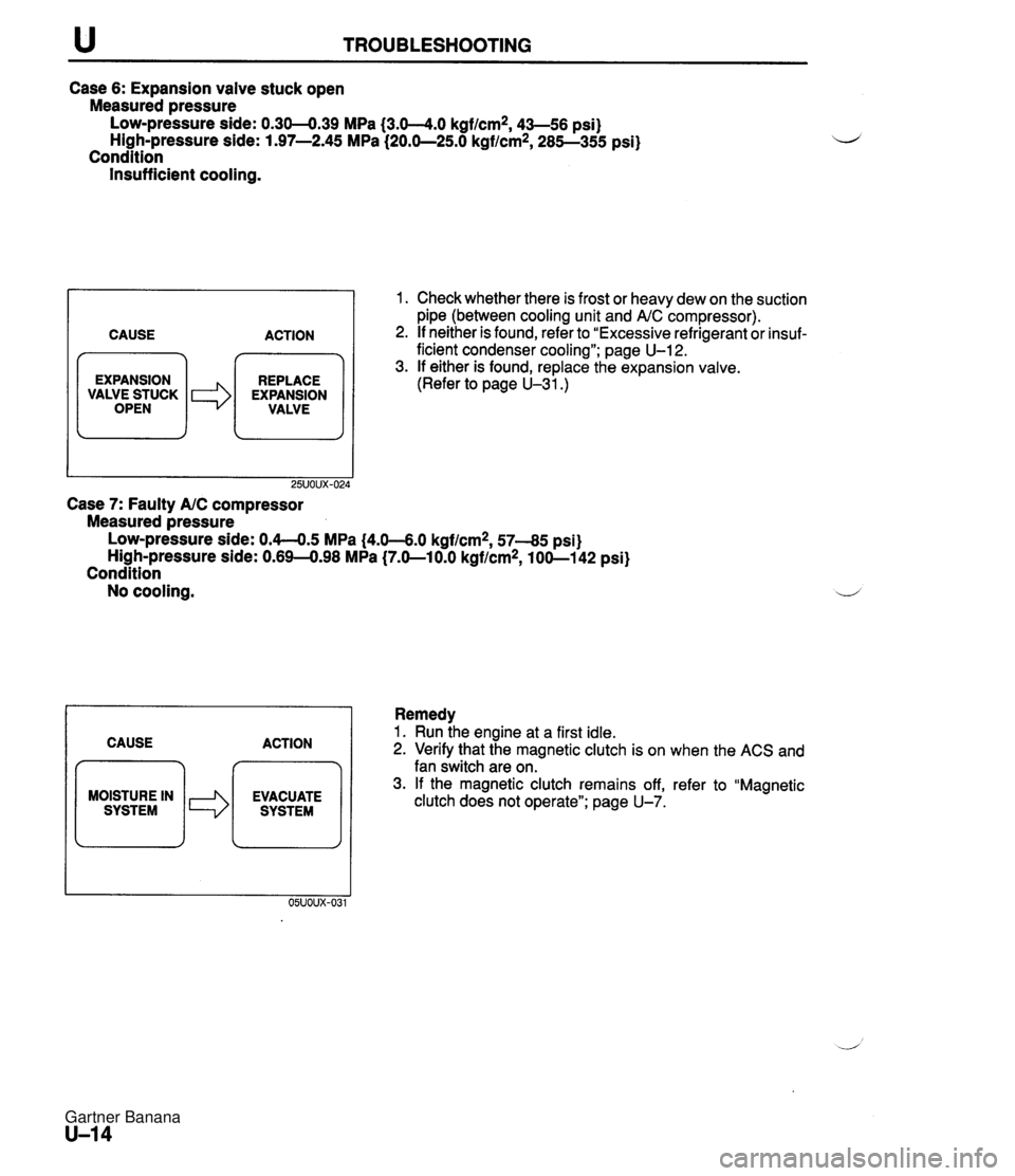
u TROUBLESHOOTING Case 6: Expansion valve stuck open Measured pressure Low-pressure side: 0.30-0.39 MPa {3.0-4.0 kgf/cm2, 43-56 psi) High-pressure side: 1.97-2.45 MPa (20.0-25.0 kgf/cm2, 285-355 psi) Condition Insufficient cooling. CAUSE ACTION 7 m EXPANSION REPLACE / VALWEiUCK I *I EXPANSION VALVE Case 7: Faulty AIC compressor Measured pressure 1. Check whether there is frost or heavy dew on the suction pipe (between cooling unit and AIC compressor). 2. If neither is found, refer to "Excessive refrigerant or insuf- ficient condenser cooling"; page U-12. 3. If either is found, replace the expansion valve. (Refer to page U-31.) LOW-pressure side: 0.4-0.5 MPa (4.0-6.0 kgf/cm2, 57-85 psi) High-pressure side: 0.69-0.98 MPa (7.0-10.0 kgflcm2, 100-1 42 psi) Condition No cooling. I 1 Remedy CAUSE ACTION MOISTURE IN 1. Run ihe engine at a first idle. 2. Verify that the magnetic clutch is on when the ACS and fan switch are on. 3. If the magnetic clutch remains off, refer to "Magnetic clutch does not operate"; page U-7. Gartner Banana
Page 1085 of 1708
AIR CONDITIONER U AIR CONDITIONER PREPARATION i, SST I I c STRUCTURAL VIEW 00007-10331 Stopper, magnetic clutch 4992-02-020 Pressure plate remover For removal and installation of magnetic clutch For removal of pressure plate 1. Cooling unit 5. Condenser fan relay Removal I Installation ......... page U-30 Inspection ................... page U-37 Disassembly I Assembly ...... page U-31 6. AX: compressor 2. Condenser Removal I Installation ......... page U-38 Removal I Installation ......... page U-33 Disassembly I Assembly ...... page U-41 w 3. Receiver drier 7. Magnetic clutch Removal / Installation ......... page U-33 Disassembly / Assembly ...... page U-39 4. A/C relay Inspection ................... page U-37 Gartner Banana
Page 1099 of 1708
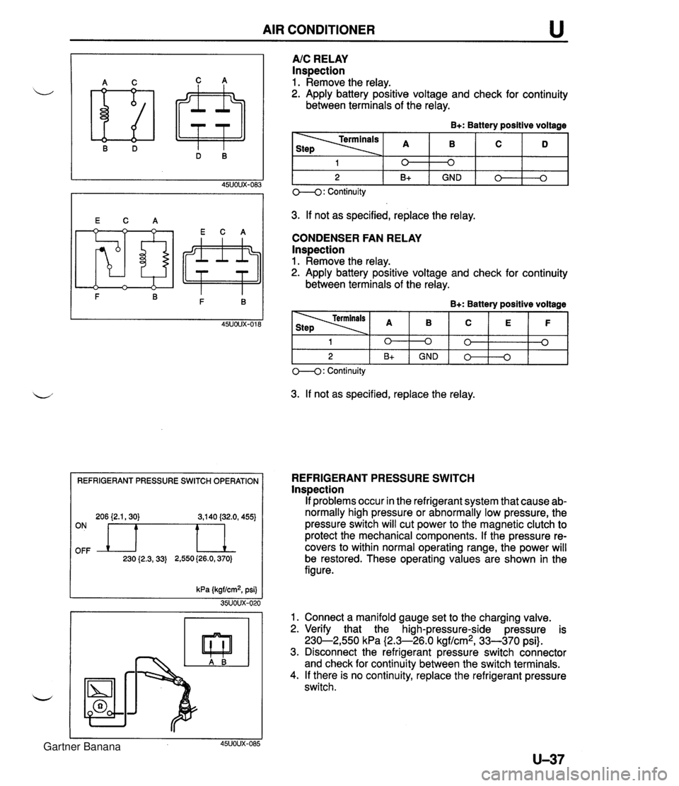
AIR CONDITIONER REFRIGERANT PRESSURE SWITCH OPERATION 206 {2.1,30) 3,140 (32.0, 455) OFF ON n 230 {2.3,33) 2,550 (26.0,370) A/C RELAY Inspection 1. Remove the relay. 2. Apply battery positive voltage and check for continuity between terminals of the relay. B+: Battery positive voltage 3. If not as specified, replace the relay. CONDENSER FAN RELAY lnspection 1. Remove the relay. 2. Apply battery positive voltage and check for continuity between terminals of the relay. B+: Battery positive voltage 1 2 O--(): Continuity 3. If not as specified, replace the relay. 0 B+ 1 2 REFRIGERANT PRESSURE SWITCH lnspection If problems occur in the refrigerant system that cause ab- normally high pressure or abnormally low pressure, the pressure switch will cut power to the magnetic clutch to protect the mechanical components. If the pressure re- covers to within normal operating range, the power will be restored. These operating values are shown in the figure. kPa (kgf/cm2, psi) 35UOUX-020 1. Connect a manifold gauge set to the charging valve. 2. Verify that the high-pressure-side pressure is 230-2,550 kPa (2.3-26.0 kgf/cm2, 33-370 psi). 3. Disconnect the refrigerant pressure switch connector and check for continuity between the switch terminals. 4. If there is no continuity, replace the refrigerant pressure switch. 45UOUX-085 0 GND 0 B+ 0 0 GND 0 0 0 0 3 Gartner Banana