Page 105 of 1708

B ASSEMBLY 4. Apply a continuous bead of silicone sealant to the oil pan along the inside of the bolt holes and overlap the ends. 5. Install the oil pan. ij Tightening torque: 7.9-10.7 N.m (80-110 kgf-cm, 70-95.4 in4bf) End Plate Install the end plate. Tightening torque: 7.9--10.7 N.m (80-110 kgf.cm, 70-95.4 in-lbf) Flywheel (MT) or drive plate (AT) 1. Remove the sealant from the bolt holes in the crankshaft and from the bolts. Caution If all of the old thread locking sealant cannot be re- moved from the bolt, it will not torque properly. - Replace the bolt. Note If a new bolt is used, do not apply thread locking seal- ant. New Mazda bolts have sealant on them. 2. Set the flywheel onto the crankshaft. 3. Apply sealant to the flywheel bolts and install them. 4. Hold the flywheel with the SST. 5. Tighten the bolts in two or three steps in the order shown. Tightening torque: 97-102 N.m (9.8-10.5 kgf+m, 71-75.9 ft.lbf) Clutch Disc and Clutch Cover (MT) Install the clutch disc and clutch cover using the SST. (Refer to section H.) Tightening torque: 18-26 N.m (1.8-2.7 kgf.m, 14--19 ftlbf) Gartner Banana
Page 112 of 1708

ASSEMBLY B r/ DEFLECTION %HECKING POINT , 7. Reverse the direction of the SST on the flywheel (MT) or drive plate (AT). 8. Tighten the pulley lock bolt. Tightening torque: 157-166 N-m (16-17 kgf.m, 116-122 ft-lbf) 9. Turn the crankshaft 1 and 516 turns clockwise, and align the timing belt pulley mark with the tension set mark. 10. Loosen the tensioner lock bolt to apply tension to the tim- ing belt. 11. Tighten the tensioner lock bolt. Tightening torque: 38-51 N-m (3.8-5.3 kgf-m, 28-38 ft4bf) 12. Turn the crankshaft 2 and 116 turns clockwise and verify that the timing marks are correctly aligned. 13. Measure the timing belt deflection by applying moderate pressure 98 N (10 kgf, 22 Ibf) midway between the two camshaft pulleys. If the deflection is not correct, repeat from step 7 above. Deflection: 9.0-11.5mm (0.36-0.45 in) at 98 N (1 0 kgf, 22 Ibf) Timing Belt Cover Install the lower, middle, and upper covers. Tightening torque: 7.9-10.7 N.m (80-110 kgf.cm, 70-95.4 in4bf) Gartner Banana
Page 351 of 1708

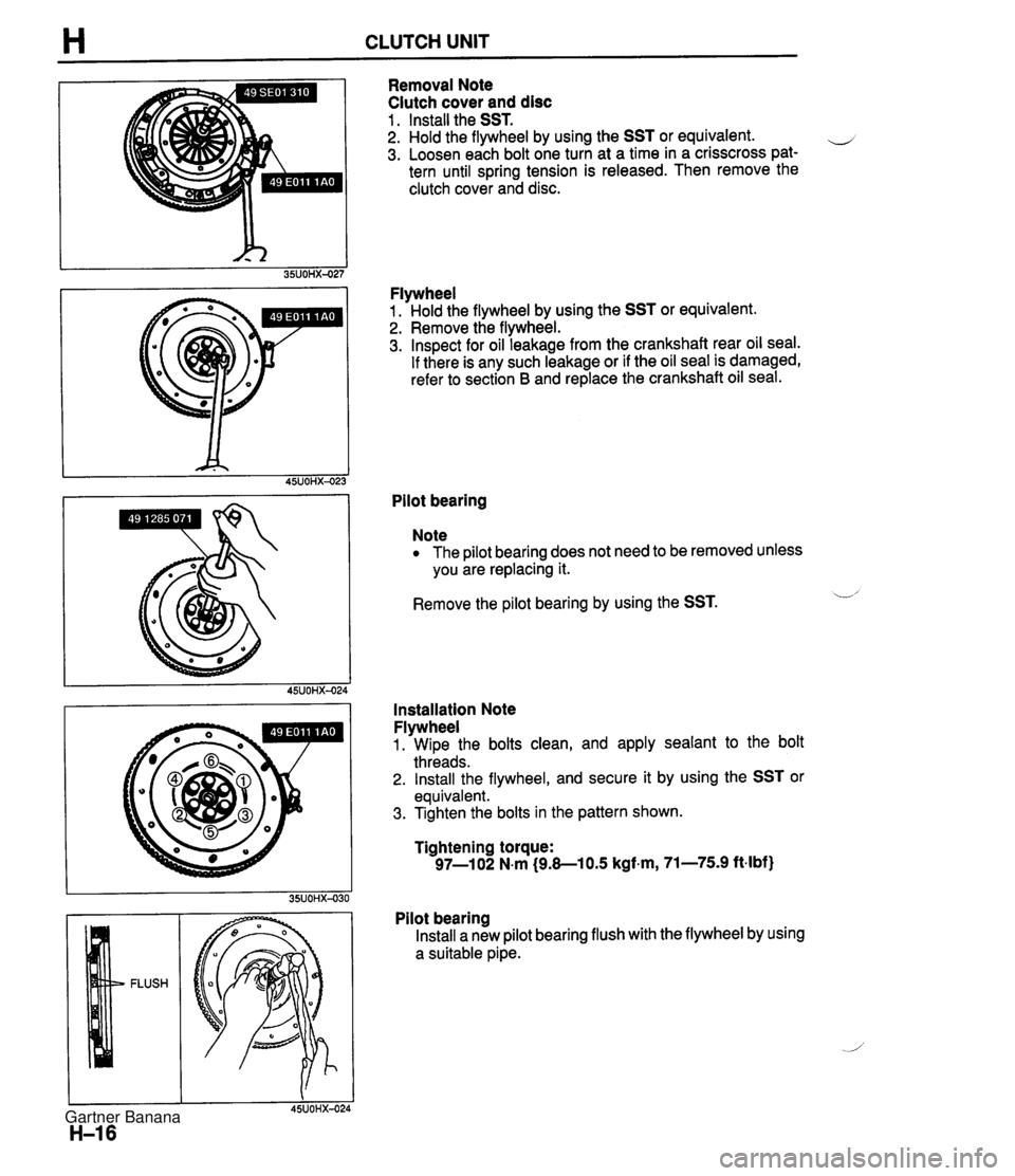
H CLUTCH UNIT Removal Note Clutch cover and disc 1 . Install the SST. 2. Hold the flywheel by using the SST or equivalent. e 3. Loosen each bolt one turn at a time in a crisscross pat- tern until spring tension is released. Then remove the clutch cover and disc. Flywheel 1. Hold the flywheel by using the SST or equivalent. 2. Remove the flywheel. 3. Inspect for oil leakage from the crankshaft rear oil seal. If there is any such leakage or if the oil seal is damaged, refer to section B and replace the crankshaft oil seal. Pilot bearing Note The pilot bearing does not need to be removed unless you are replacing it. Remove the pilot bearing by using the SST. L' Installation Note Flywheel 1. Wipe the bolts clean, and apply sealant to the bolt threads. 2. Install the flywheel, and secure it by using the SST or equivalent. 3. Tighten the bolts in the pattern shown. Tightening torque: 97-1 02 N.m (9.8-1 0.5 kgf.m, 71-75.9 ft-lbf) Pilot bearing Install a new pilot bearing flush with the flywheel by using a suitable pipe. Gartner Banana
Page 352 of 1708

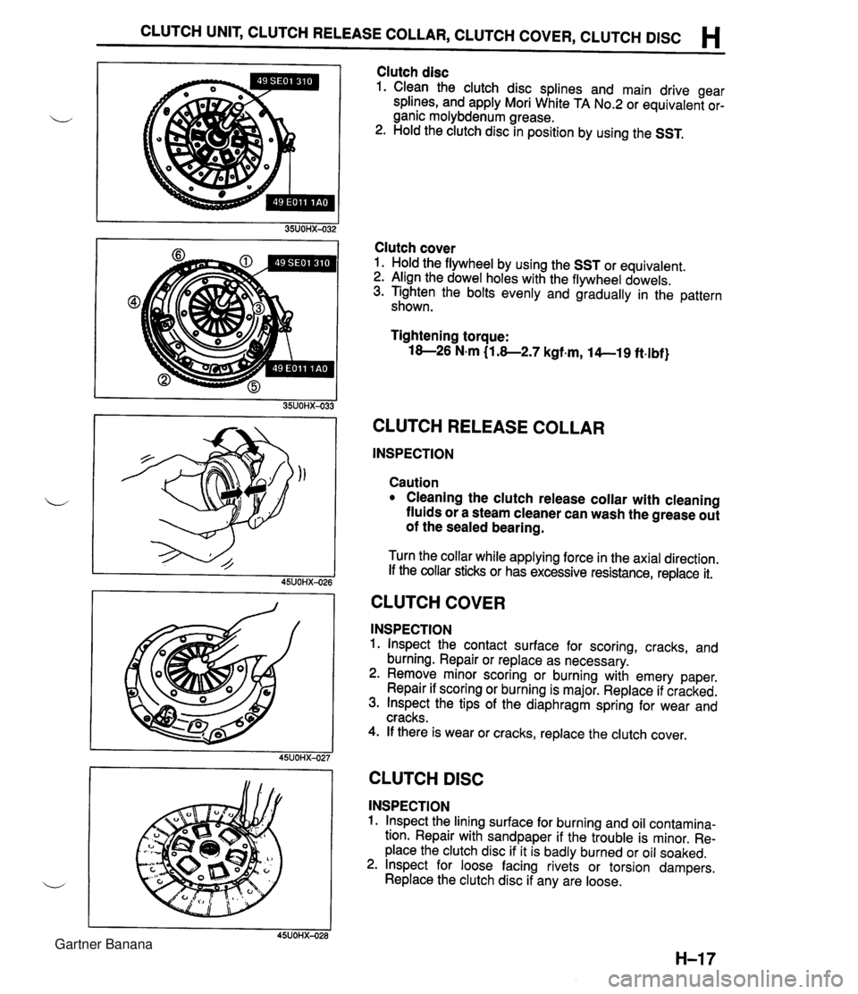
CLUTCH UNIT, CLUTCH RELEASE COLLAR, CLUTCH COVER, CLUTCH DlSC H Clutch disc 1. Clean the clutch disc splines and main drive gear splines, and apply Mori White TA No.2 or equivalent or- ganic molybdenum grease. 2. Hold the clutch disc in position by using the SST. Clutch cover 1. Hold the flywheel by using the SST or equivalent. 2. Align the dowel holes with the flywheel dowels. 3. Tighten the bolts evenly and gradually in the pattern shown. Tightening torque: 18-26 N.m (1.8-2.7 kgf.m, 14--19 ft.lbf} CLUTCH RELEASE COLLAR INSPECTION Caution Cleaning the clutch release collar with cleaning fluids or a steam cleaner can wash the grease out of the sealed bearing. Turn the collar while applying force in the axial direction. If the collar sticks or has excessive resistance, replace it. CLUTCH COVER INSPECTION 1. lnspect the contact surface for scoring, cracks, and burning. Repair or replace as necessary. 2. Remove minor scoring or burning with emery paper. Repair if scoring or burning is major. Replace if cracked. 3. lnspect the tips of the diaphragm spring for wear and cracks. 4. If there is wear or cracks, replace the clutch cover. I I 45UOHX-027 CLUTCH DlSC INSPECTION 1. lnspect the lining surface for burning and oil contamina- tion. Repair with sandpaper if the trouble is minor. Re- place the clutch disc if it is badly burned or oil soaked. 2. lnspect for loose facing rivets or torsion dampers. Replace the clutch disc if any are loose. Gartner Banana
Page 611 of 1708
M DIFFERENTIAL 5. Separate the driveshaft from the differential and sus- pend it. 6. Remove the output shaft by using two pry bars as shown in the figure. J 7. Remove the oil seal. 8. Apply lithium-based grease to the new oil seal lip and install it by using'the SST. 9. Install the new clips. 10. Install the output shaft into the side gears by lightly tap- ping with a plastic hammer. 11. Verify that the output shaft is hooked into the side gears by pulling it by hand. ./ 12. Align the marks and install the drive shaft. Tightening torque: 54-64 N.m (5.5--6.5 kgf.m, 40-47 ft-lbf) 13. Install the upper arm installation bolt and nut. Tightening torque: 46-67 N.m (4.7-6.8 kgf.m, 34--49 ftlbf) 14. Add the specified oil. 15. Adjust the rear wheel alignment. (Refer to section R.) I Gartner Banana
Page 615 of 1708
M DIFFERENTIAL Installation note Differential 1. Connect the drive shaft to the output shaft with the marks aligned. 2. Install the differential. - JOMX- Tightening torque 0: 83-98 N-m (8.5-10 kgf.m, 61-72 ft4bf) @I: 18-26 N.m (1.8-2.7 kgf.m, 13-20 ft.lbf) 3. Adjust the rear wheel alignment if the upper arm installa- tion bolt and nut were removed. (section R.) Power plant frame (PPF) 1. Install the differential mounting spacer. Tightening torque: 37-52 N-m (3.8-5.3 kgf.m, 27-38 ftdbf} .i 2. Support the transmission with a jack so that it is level. 3. Position the PPF and snugly tighten the transmission- side bolts by hand. 4. Verify that the sleeve is installed into the block. 5. Install the spacer and bolts and snugly tighten them. The reamer bolt should be installed in the forward hole. 6. Snugly install the power plant frame bracket. 7. Tighten the transmission-side bolts. Tightening torque: lO4--123 N.m (1 0.6-1 2.6 kgf.m, 77-91 ft4bf) Gartner Banana
Page 636 of 1708
MANUAL STEERING , N Removal / Installation 1. Disconnect the negative battery cable. 2. Remove in the order shown in the figure, referring to Removal Note. ,, 3. Inspect all parts and repair or replace as necessary. 4. Install in the reverse order of removal. 5. Tighten all necessary nuts and bolts to the specified torque. 6. After installation, check if the horn sounds. If the horn does not sound, remove the air bag module and connect the module connectors. (Refer to section T.) 1. Air bag module 6. Lower panel Removal 1 Installation .......... section T 7. Key interlock cable (Automatic transmission) 2. Locknut 8. Intermediate shaft bolt 3. Steering wheel 9. Steering shaft w ............... Removal Note page N-10 Disassembly 1 Inspection / 4. Column cover Assembly .................. page N-10 5. Combination switch Removal / Installation .......... section T Gartner Banana
Page 652 of 1708

ENGINE SPEED SENSING POWER STEERING N STEERING GEAR AND LINKAGE Removal / Installation 1. Turn the wheels to the straight-ahead position. 2. Loosen the wheel lug nuts. 3. On level ground, jack up the front of the vehicle and support it on safety stands. 4. Remove the wheels. Note Turning the steering wheel while the steering gear is removed will make reinstallation difficult. Do not turn the steering wheel while the steering gear is removed. If the steering wheel is turned in that condi- tion, the clockspring connector may have to be adjusted. (Refer to section T.) 5. Remove in the order shown in the figure, referring to Removal Note. 6. With the wheels in the straight-ahead position, install in the reverse order of removal. 7. Tighten all necessary bolts and nuts to the specified torque. 8. After installation: (1) Check for fluid leakage. (Refer to page N-22.) (2) Bleed air from the system. (Refer to page N-21.) (3) Adjust the front wheel alignment. (Refer to section R.) 1. Cotter pin 5. Pressure pipe 2. Nut ~emovai Note ............... page N-26 3. Tie-rod endlsteering knuckle 6. Return hose Removal Note ............... page N- 7 7. Mounting bracket bolt 4. Bolt 8. Steering gear and linkage Gartner Banana