1994 JEEP WRANGLER sensor
[x] Cancel search: sensorPage 926 of 1770

switch will supply a ground circuit to the powertrain
control module (PCM).The switch is available
only with 4.0L engine when supplied with the
optional police package.
CRUISE MODE
When the engine is at operating temperature, this
is a Closed Loop mode. At cruising speed, the power-
train control module (PCM) receives inputs from:
²Air conditioning select signal (if equipped)
²Air conditioning request signal (if equipped)
²Battery voltage
²Engine coolant temperature sensor
²Crankshaft position sensor
²Intake manifold air temperature sensor
²Manifold absolute pressure (MAP) sensor
²Throttle position sensor (TPS)
²Camshaft position sensor signal (in the distributor)
²Park/Neutral switch (gear indicator signalÐauto.
trans. only)
²Oxygen (O2S) sensor
Based on these inputs, the following occurs:
²Voltage is applied to the fuel injectors with the
PCM. The PCM will then adjust the injector pulse
width by turning the ground circuit to each individ-
ual injector on and off.
²The PCM monitors the O2S sensor input and ad-
justs air-fuel ratio. It also adjusts engine idle speed
through the idle air control (IAC) motor.
²The PCM adjusts ignition timing by turning the
ground path to the coil on and off.
²The PCM operates the A/C compressor clutch
through the clutch relay. This happens if A/C has
been selected by the vehicle operator and requested
by the A/C thermostat.
ACCELERATION MODE
This is an Open Loop mode. The powertrain control
module (PCM) recognizes an abrupt increase in
throttle position or MAP pressure as a demand for
increased engine output and vehicle acceleration.
The PCM increases injector pulse width in response
to increased throttle opening.
DECELERATION MODE
When the engine is at operating temperature, this
is an Open Loop mode. During hard deceleration, the
powertrain control module (PCM) receives the follow-
ing inputs.
²Air conditioning select signal (if equipped)
²Air conditioning request signal (if equipped)
²Battery voltage
²Engine coolant temperature sensor
²Crankshaft position sensor
²Intake manifold air temperature sensor
²Manifold absolute pressure (MAP) sensor
²Throttle position sensor (TPS)
²Camshaft position sensor signal (in the distributor)²Park/Neutral switch (gear indicator signalÐauto.
trans. only)
If the vehicle is under hard deceleration with the
proper rpm and closed throttle conditions, the PCM
will ignore the oxygen sensor input signal. The PCM
will enter a fuel cut-off strategy in which it will not
supply battery voltage to the injectors. If a hard de-
celeration does not exist, the PCM will determine the
proper injector pulse width and continue injection.
Based on the above inputs, the PCM will adjust en-
gine idle speed through the idle air control (IAC) mo-
tor.
The PCM adjusts ignition timing by turning the
ground path to the coil on and off.
The PCM opens the ground circuit to the A/C
clutch relay to disengage the A/C compressor clutch.
This is done until the vehicle is no longer under de-
celeration (if the A/C system is operating).
WIDE OPEN THROTTLE MODE
This is an Open Loop mode. During wide open
throttle operation, the powertrain control module
(PCM) receives the following inputs.
²Battery voltage
²Crankshaft position sensor
²Engine coolant temperature sensor
²Intake manifold air temperature sensor
²Manifold absolute pressure (MAP) sensor
²Throttle position sensor (TPS)
²Camshaft position sensor signal (in the distributor)
During wide open throttle conditions, the following
occurs:
²Voltage is applied to the fuel injectors with the
powertrain control module (PCM). The PCM will
then control the injection sequence and injector pulse
width by turning the ground circuit to each individ-
ual injector on and off. The PCM ignores the oxygen
sensor input signal and provides a predetermined
amount of additional fuel. This is done by adjusting
injector pulse width.
²The PCM adjusts ignition timing by turning the
ground path to the coil on and off.
²The PCM opens the ground circuit to the A/C
clutch relay to disengage the A/C compressor clutch.
This will be done for approximately 15 seconds (if the
air conditioning system is operating).
If the vehicle has a manual transmission, the up-
shift light is operated by the PCM.
IGNITION SWITCH OFF MODE
When ignition switch is turned to OFF position,
the PCM stops operating the injectors, ignition coil,
ASD relay and fuel pump relay.
THROTTLE BODY
Filtered air from the air cleaner enters the intake
manifold through the throttle body (Fig. 25). Fuel
does not enter the intake manifold through the throt-
JFUEL SYSTEM 14 - 29
Page 927 of 1770

tle body. Fuel is sprayed into the manifold by the fuel
injectors. The throttle body is mounted on the intake
manifold. It contains an air control passage (Fig. 26)
controlled by an Idle Air Control (IAC) motor. The air
control passage is used to supply air for idle condi-
tions. A throttle valve (plate) is used to supply air for
above idle conditions.
The throttle position sensor (TPS) and idle air con-
trol (IAC) motor are attached to the throttle body.
The accelerator pedal cable, speed control cable and
transmission control cable (when equipped) are con-
nected to the throttle arm.
A (factory adjusted) set screw is used to mechani-
cally limit the position of the throttle body throttle
plate.Never attempt to adjust the engine idle
speed using this screw.All idle speed functions are
controlled by the PCM.
FUEL RAIL
The fuel rail supplies fuel to the injectors and is
mounted to the intake manifold (Fig. 27). The fuelpressure regulator is attached to the rail and the fuel
pressure test port is integral with the rail. The fuel
rail is not repairable.
FUEL PRESSURE REGULATOR
The fuel pressure regulator (Fig. 28) is a mechani-
cal device that is not controlled by the powertrain
control module (PCM).
The fuel pressure regulator used is a vacuum bal-
anced, nonadjustable type. The regulator is mounted
on the output end of the fuel rail and is connected to
intake manifold vacuum. The fuel return tube (to the
fuel tank) is connected to the fuel pressure regulator.
The regulator is calibrated to maintain fuel system
pressure at approximately 214 kPa (31 psi). This is
with vacuum applied while the engine is at idle. Fuel
pressure will be 55-69 kPa (8-10 psi) higher if vac-
uum is not applied to the regulator.
The pressure regulator contains a diaphragm, cali-
brated spring and a fuel return valve (Fig. 29). Fuel
pressure operates on one side of the regulator, while
spring pressure and intake manifold vacuum operate
on the other side. Spring pressure on one side of the
Fig. 27 Fuel RailÐTypical
Fig. 28 Fuel Pressure RegulatorÐTypical
Fig. 25 Throttle BodyÐTypical
Fig. 26 Idle Air Control Passage
14 - 30 FUEL SYSTEMJ
Page 929 of 1770

MULTI-PORT FUEL INJECTION (MFI)ÐGENERAL DIAGNOSIS
INDEX
page page
Automatic Shutdown (ASD) Relay Testing...... 43
Camshaft Position Sensor Test.............. 43
Crankshaft Position Sensor Test............. 44
Diagnostic Trouble Code (DTC).............. 51
DRB Scan Tool.......................... 51
Engine Coolant Temperature Sensor Test...... 43
Extended Idle Switch Test.................. 45
Fuel Pump Relay Testing.................. 44
Fuel System Pressure Test................. 48
General Information....................... 32
Idle Air Control Motor Test................. 46
Injector Test............................ 48
Intake Air Temperature Sensor Test.......... 43Manifold Absolute Pressure (MAP) Sensor Test . 44
On-Board Diagnostics (OBD)................ 48
Oxygen Sensor (O2S) Heating Element Test.... 45
Powertrain Control Module (PCM) 60-Way
Connector............................ 38
RelaysÐOperation/Testing.................. 47
Starter Motor Relay Test................... 48
System Schematics....................... 38
Throttle Position Sensor (TPS) Test.......... 45
Torque Converter Clutch Relay Test.......... 45
Vehicle Speed Sensor Test................. 45
Visual Inspection......................... 32
GENERAL INFORMATION
All 2.5L 4 cylinder and 4.0L 6 cylinder engines are
equipped with sequential Multi-Port Fuel Injection
(MFI). The MFI system provides precise air/fuel ra-
tios for all driving conditions.
VISUAL INSPECTION
A visual inspection for loose, disconnected, or incor-
rectly routed wires and hoses should be made. This
should be done before attempting to diagnose or ser-
vice the fuel injection system. A visual check will
help spot these faults and save unnecessary test and
diagnostic time. A thorough visual inspection will in-
clude the following checks:
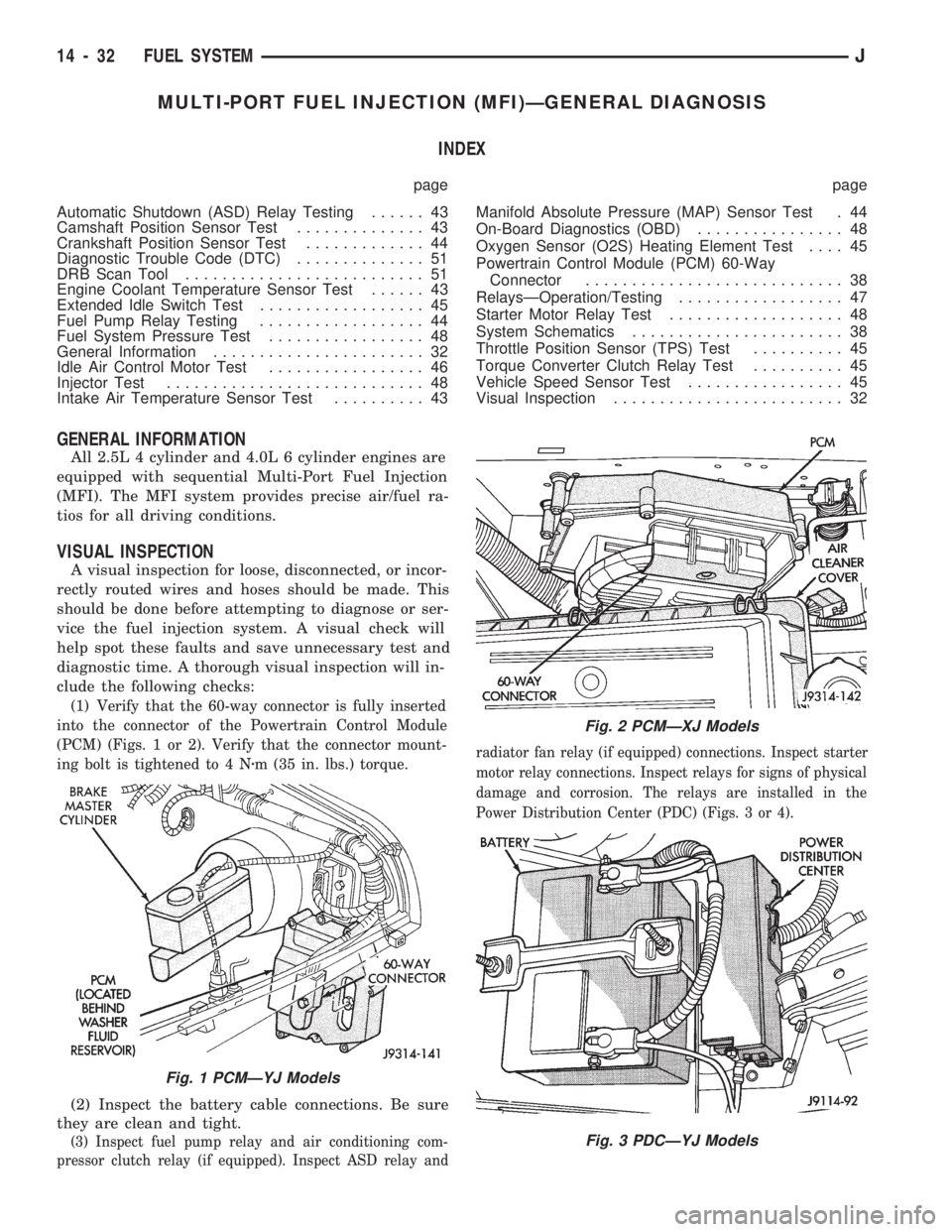
(1) Verify that the 60-way connector is fully inserted
into the connector of the Powertrain Control Module
(PCM) (Figs. 1 or 2). Verify that the connector mount-
ing bolt is tightened to 4 Nzm (35 in. lbs.) torque.
(2) Inspect the battery cable connections. Be sure
they are clean and tight.
(3) Inspect fuel pump relay and air conditioning com-
pressor clutch relay (if equipped). Inspect ASD relay andradiator fan relay (if equipped) connections. Inspect starter
motor relay connections. Inspect relays for signs of physical
damage and corrosion. The relays are installed in the
Power Distribution Center (PDC) (Figs. 3 or 4).
Fig. 1 PCMÐYJ Models
Fig. 2 PCMÐXJ Models
Fig. 3 PDCÐYJ Models
14 - 32 FUEL SYSTEMJ
Page 930 of 1770

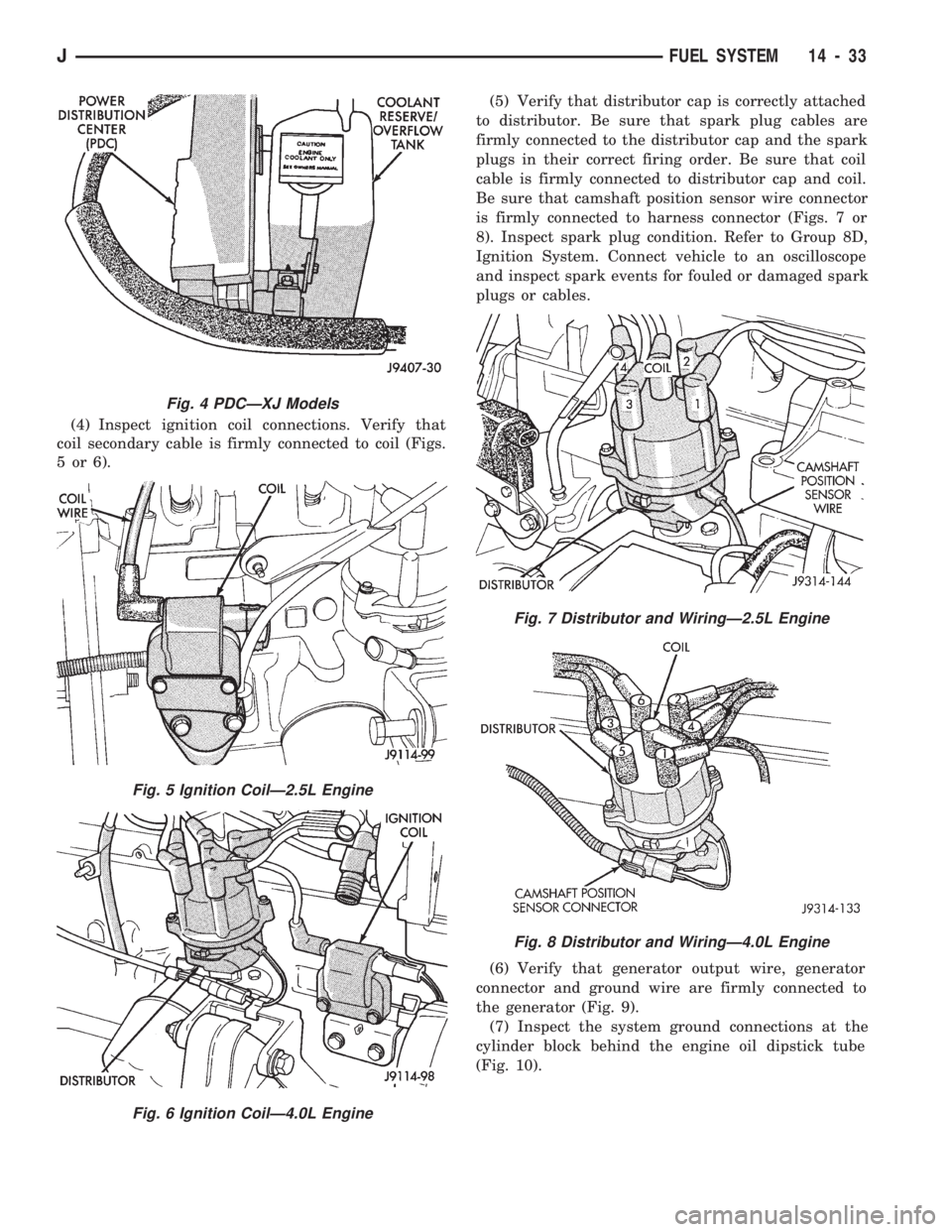
(4) Inspect ignition coil connections. Verify that
coil secondary cable is firmly connected to coil (Figs.
5or6).(5) Verify that distributor cap is correctly attached
to distributor. Be sure that spark plug cables are
firmly connected to the distributor cap and the spark
plugs in their correct firing order. Be sure that coil
cable is firmly connected to distributor cap and coil.
Be sure that camshaft position sensor wire connector
is firmly connected to harness connector (Figs. 7 or
8). Inspect spark plug condition. Refer to Group 8D,
Ignition System. Connect vehicle to an oscilloscope
and inspect spark events for fouled or damaged spark
plugs or cables.
(6) Verify that generator output wire, generator
connector and ground wire are firmly connected to
the generator (Fig. 9).
(7) Inspect the system ground connections at the
cylinder block behind the engine oil dipstick tube
(Fig. 10).
Fig. 4 PDCÐXJ Models
Fig. 5 Ignition CoilÐ2.5L Engine
Fig. 6 Ignition CoilÐ4.0L Engine
Fig. 7 Distributor and WiringÐ2.5L Engine
Fig. 8 Distributor and WiringÐ4.0L Engine
JFUEL SYSTEM 14 - 33
Page 932 of 1770

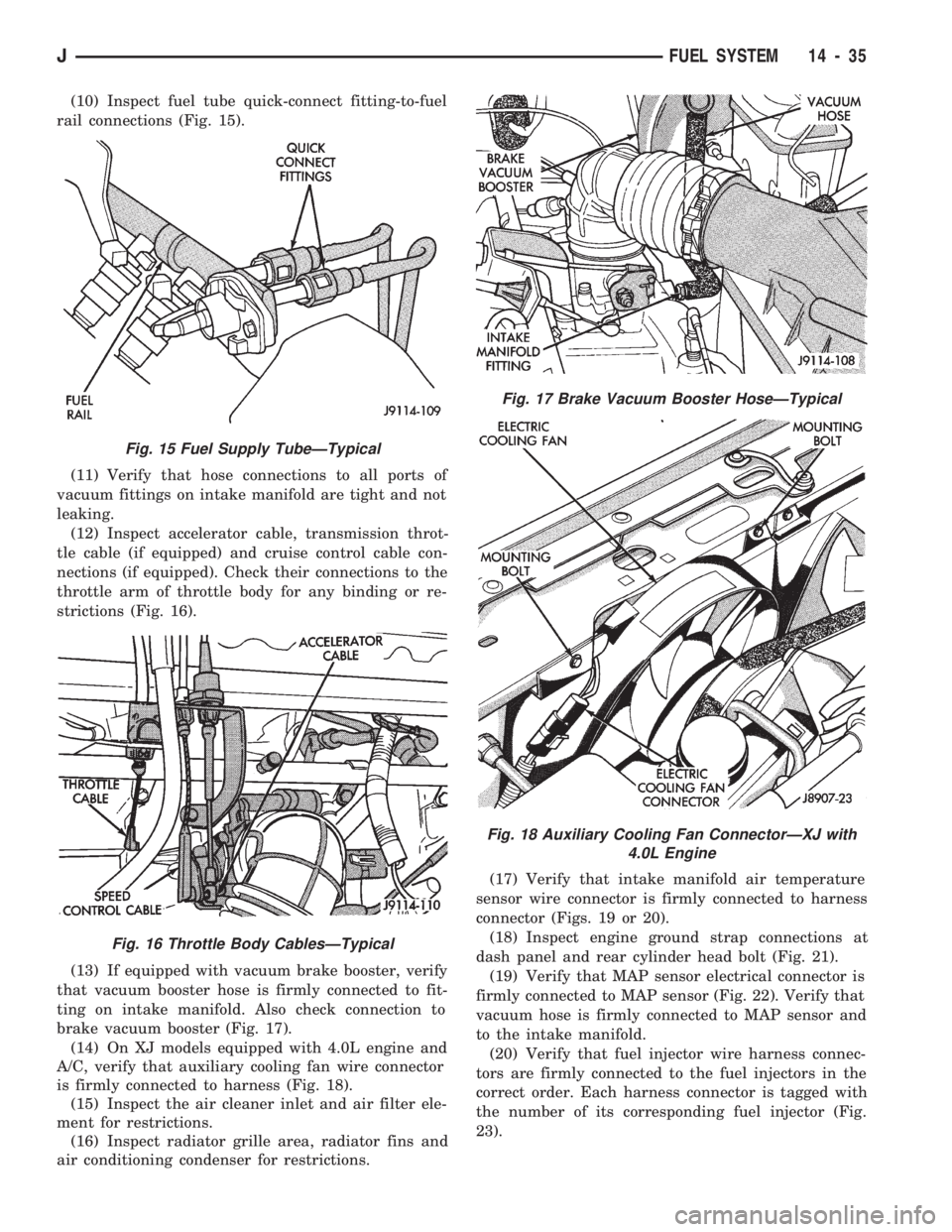
(10) Inspect fuel tube quick-connect fitting-to-fuel
rail connections (Fig. 15).
(11) Verify that hose connections to all ports of
vacuum fittings on intake manifold are tight and not
leaking.
(12) Inspect accelerator cable, transmission throt-
tle cable (if equipped) and cruise control cable con-
nections (if equipped). Check their connections to the
throttle arm of throttle body for any binding or re-
strictions (Fig. 16).
(13) If equipped with vacuum brake booster, verify
that vacuum booster hose is firmly connected to fit-
ting on intake manifold. Also check connection to
brake vacuum booster (Fig. 17).
(14) On XJ models equipped with 4.0L engine and
A/C, verify that auxiliary cooling fan wire connector
is firmly connected to harness (Fig. 18).
(15) Inspect the air cleaner inlet and air filter ele-
ment for restrictions.
(16) Inspect radiator grille area, radiator fins and
air conditioning condenser for restrictions.(17) Verify that intake manifold air temperature
sensor wire connector is firmly connected to harness
connector (Figs. 19 or 20).
(18) Inspect engine ground strap connections at
dash panel and rear cylinder head bolt (Fig. 21).
(19) Verify that MAP sensor electrical connector is
firmly connected to MAP sensor (Fig. 22). Verify that
vacuum hose is firmly connected to MAP sensor and
to the intake manifold.
(20) Verify that fuel injector wire harness connec-
tors are firmly connected to the fuel injectors in the
correct order. Each harness connector is tagged with
the number of its corresponding fuel injector (Fig.
23).
Fig. 15 Fuel Supply TubeÐTypical
Fig. 16 Throttle Body CablesÐTypical
Fig. 17 Brake Vacuum Booster HoseÐTypical
Fig. 18 Auxiliary Cooling Fan ConnectorÐXJ with
4.0L Engine
JFUEL SYSTEM 14 - 35
Page 933 of 1770

(21) Verify that harness connectors are firmly con-
nected to idle air control (IAC) motor and throttle po-
sition sensor (TPS) (Figs. 19, 20 or 24).
Fig. 19 Sensor LocationÐ4.0L Engine
Fig. 20 Sensor LocationÐ2.5L Engine
Fig. 21 Engine Ground Strap ConnectionsÐTypical
Fig. 22 MAP SensorÐTypical
Fig. 23 Fuel Injector Wire HarnessÐTypical
Fig. 24 IAC Motor and TPSÐ2.5L Engine
14 - 36 FUEL SYSTEMJ
Page 934 of 1770

(22) Verify that wire harness connector is firmly
connected to the coolant temperature sensor (Fig.
25).
(23) Verify that oxygen sensor wire connector is
firmly connected to the sensor. Inspect sensor and
connector for damage (Fig. 26).(24) Raise and support the vehicle.
(25) Inspect for pinched or leaking fuel tubes. In-
spect for pinched cracked or leaking fuel hoses.
(26) Inspect for exhaust system restrictions such as
pinched exhaust pipes, collapsed muffler or plugged
catalytic convertor.
(27) If equipped with automatic transmission, ver-
ify that electrical harness is firmly connected to
park/neutral safety switch. Refer to Automatic
Transmission section of Group 21.
(28) Verify that the harness connector is firmly
connected to the vehicle speed sensor (Fig. 27).
Fig. 25 Coolant Temperature SensorÐTypical
Fig. 26 Oxygen Sensor LocationÐTypical
Fig. 27 Vehicle Speed SensorÐTypical
JFUEL SYSTEM 14 - 37
Page 940 of 1770

AUTOMATIC SHUT DOWN (ASD) RELAY TESTING
To perform a complete test of the ASD relay and
its circuitry, refer to the DRB scan tool and appropri-
ate Powertrain Diagnostics Procedures manual. To
test the relay only, refer to RelaysÐOperation/Test-
ing in this section of the group.
CAMSHAFT POSITION SENSOR TEST
Refer to Group 8D, Ignition Systems, for Camshaft
Position Sensor testing.
ENGINE COOLANT TEMPERATURE SENSOR TEST
To perform a complete test of the engine coolant
temperature sensor and its circuitry, refer to DRB
scan tool and appropriate Powertrain Diagnostics
Procedures manual. To test the sensor only, refer to
the following:
Disconnect wire harness connector from engine
coolant temperature sensor (Fig. 34).
Test the resistance of the sensor with a high input
impedance (digital) volt-ohmmeter. The resistance
should be less than 1000 ohms with the engine at its
correct operating temperature. Refer to the Coolant
Temperature Sensor/Manifold Air Temperature Sen-
sor resistance chart. Replace the sensor if it is not
within the range of resistance specified in the chart.
Test continuity of the wire harness. Do this be-
tween the Powertrain Control Module (PCM) wire
harness connector terminal-2 and the sensor connec-
tor terminal. Also test continuity of wire harness ter-
minal-4 to the sensor connector terminal. Repair the
wire harness if an open circuit is indicated.
INTAKE AIR TEMPERATURE SENSOR TEST
To perform a complete test of the sensor and its cir-
cuitry, refer to DRB scan tool and appropriate Pow-
ertrain Diagnostics Procedures manual. To test the
sensor only, refer to the following:Disconnect the wire harness connector from the in-
take manifold air temperature sensor (Figs. 35 or
36).
Test the resistance of the sensor with an input im-
pedance (digital) volt-ohmmeter. The resistance
should be less than 4000 ohms with the engine at op-
erating temperature. The longer the engine idles, the
warmer the intake manifold temperature will be-
come. Refer to the Coolant Temperature Sensor/Man-
ifold Air Temperature Sensor resistance chart.
Replace the sensor if it is not within the range of re-
sistance specified in the chart.
Test the resistance of the wire harness. Do this be-
tween the Powertrain Control Module (PCM) wire
Fig. 34 Coolant Temperature SensorÐTypical
SENSOR RESISTANCE (OHMS)ÐCOOLANT
TEMPERATURE SENSOR/MANIFOLD AIR TEM-
PERATURE
Fig. 35 Air Temperature SensorÐ2.5L Engine
JFUEL SYSTEM 14 - 43