1994 JEEP CHEROKEE Hydraulic booster fluid
[x] Cancel search: Hydraulic booster fluidPage 148 of 1784
BRAKES
CONTENTS
page page
ABS BRAKE DIAGNOSIS.................. 3
ABS COMPONENT SERVICE.............. 47
ABS SYSTEM OPERATION............... 39
ANTILOCK BRAKE SYSTEM OPERATION.... 43
BRAKE BLEEDINGÐBRAKE FLUID AND
LEVELÐBRAKELINES AND HOSES....... 13
BRAKE PEDAL AND BRAKELIGHT SWITCH . . 65
DISC BRAKES.......................... 24DRUM BRAKES........................ 34
GENERAL INFORMATION.................. 1
PARKING BRAKES...................... 56
POWER BRAKE BOOSTER................ 22
SERVICE BRAKE DIAGNOSIS.............. 7
SPECIFICATIONS....................... 67
STANDARD MASTER CYLINDER........... 20
GENERAL INFORMATION
INDEX
page page
Antilock Brake System (ABS)................ 1
Brake Fluid/Lubricants/Cleaning Solvents........ 1
Brake Safety Precautions................... 2
Brake Warning Lights...................... 1
Brakelining Material........................ 1Hydraulic Components..................... 1
Jeep Body Code Letters.................... 2
Power Brakes............................ 1
Wheel Brake Components................... 1
WHEEL BRAKE COMPONENTS
Front disc and rear drum brakes are used on all
models. The disc brake components consist of single
piston calipers and ventilated rotors. The rear drum
brakes are dual shoe, units with cast brake drums.
The parking brake mechanism is lever and cable
operated. The cables are attached to actuating levers
mounted on the rear drum brake secondary shoes.
The parking brake mechanism is operated by a foot
pedal on YJ models and a hand lever on XJ models.
POWER BRAKES
Power brakes are standard on all models. A vac-
uum operated power booster is used for standard and
ABS brake applications.
HYDRAULIC COMPONENTS
A dual reservoir master cylinder is used for all
standard brake applications. A combination propor-
tioning valve/pressure differential switch is used. A
center feed style master cylinder is used for ABS
brake applications.
BRAKELINING MATERIAL
The factory installed brakelining on all models con-
sists of an organic base material combined with me-
tallic particles. The lining does not contain asbestos.
BRAKE WARNING LIGHTS
A red, brake warning light is used to alert the
driver if a pressure differential exists between the
front and rear hydraulic systems. The light also
alerts the driver when the parking brakes are ap-
plied. The light illuminates for a few seconds at start
up as part of a bulb check procedure.
An additional warning light is used on models with
antilock brakes. This light is amber in color and is
located in the same side of the instrument cluster as
the red warning light. The amber light illuminates
only when an ABS system fault occurs.
ANTILOCK BRAKE SYSTEM (ABS)
An antilock brake system (ABS) is available on
XJ/YJ models. The system is an electronically oper-
ated, all-wheel brake control system. The ABS sys-
tem is designed to retard wheel lockup during
periods of high wheel slip braking. Refer to the anti-
lock brake section for operation and service informa-
tion.
BRAKE FLUID/LUBRICANTS/CLEANING SOLVENTS
Recommended fluid for all Jeep vehicles is Mopar
DOT 3 brake fluid, or an equivalent meeting SAE
J1703 and DOT 3 standards.
JBRAKES 5 - 1
Page 154 of 1784
SERVICE BRAKE DIAGNOSIS
INDEX
page page
Component Inspection...................... 8
Diagnosing Parking Brake Problems.......... 10
Diagnosing Service Brake Problems........... 8
Diagnosis Procedures...................... 7
General Information........................ 7Master Cylinder/Power Booster Test.......... 11
Power Booster Check Valve Test............ 11
Power Booster Vacuum Test................ 12
Preliminary Brake Check.................... 7
Road Testing............................ 7
GENERAL INFORMATION
The diagnosis information in this section covers
service brake components which include:
²disc brake calipers
²disc brakeshoes
²drum brake wheel cylinders
²drum brakeshoes and brake drums
²drum brake support plates
²parking brake mechanism
²master cylinder/combination valve
²vacuum power brake booster
²brake pedal and brakelight switch
²brake warning light
DIAGNOSIS PROCEDURES
Service brake diagnosis involves determining if a
problem is related to a mechanical, hydraulic or vac-
uum operated component. A preliminary brake
check, followed by road testing and component in-
spection are needed to determine a problem cause.
Road testing will either verify proper brake opera-
tion or confirm the existence of a problem. Compo-
nent inspection will, in most cases, identify the
actual part responsible for a problem.
The first diagnosis step is the preliminary brake
check. This involves inspecting fluid level, parking
brake action, wheel and tire condition, checking for
obvious leaks or component damage and testing
brake pedal response. A road test will confirm or
deny the existence of a problem. The final diagnosis
procedure involves road test analysis and a visual in-
spection of brake components.
PRELIMINARY BRAKE CHECK
(1) If amber antilock light is illuminated, refer to
Antilock Brake System Diagnosis. However, if red
warning light is illuminated, or if neither warning
light is illuminated, continue with diagnosis.
(2) Check condition of tires and wheels. Damaged
wheels and worn, damaged, or underinflated tires
can cause pull, shudder, tramp and a condition simi-
lar to grab.
(3) If complaint was based on noise when braking,
check suspension components. Jounce front and rearof vehicle and listen for noise that might be caused
by loose, worn, or damaged suspension or steering
components.
(4) Inspect brake fluid level:
(a) If vehicle has one-piece master cylinder, fluid
level should be to 6 mm (1/4 in.) of reservoir rim. If
vehicle two-piece, removable reservoir, correct level
is to top of indicator rings in reservoir.
(b) On models with ABS brakes, preferred level
is to MAX mark on reservoir. Acceptable level is
between MAX and MIN marks.
(c) Remember that fluid level in the front and
rear reservoir compartments will decrease in pro-
portion to normal lining wear. However, if fluid
level is abnormally low, look for leaks at calipers,
wheel cylinders, brakelines and master cylinder.
(5) Inspect brake fluid condition:
(a) Fluid should be reasonably clear and free of
foreign material.Note that brake fluid tends to
darken over time. This is normal and should
not be mistaken for contamination. If fluid is
clear of foreign material, it is OK.
(b) If fluid is highly discolored, or appears to con-
tain foreign material, drain out a sample with a
clean suction gun. Pour sample in a glass container
and note condition.
(c) If fluid separates into layers, obviously con-
tains oil, or a substance other than brake fluid,
system seals and cups will have to be replaced and
hydraulic system flushed.
(6) Check parking brake operation. Verify free
movement and full release of cables and foot pedal or
hand lever. Also note if vehicle was being operated
with parking brake partially applied.
(7) Check brake pedal operation. Verify that pedal
does not bind and has adequate free play. If pedal
lacks free play, check pedal and power booster for be-
ing loose or for bind condition. Do not road test until
condition is corrected.
(8) If components inspected look OK, road test the
vehicle.
ROAD TESTING
(1) If amber warning light is illuminated, problem
is with antilock system component. Refer to Antilock
Brake System Diagnosis.
JBRAKES 5 - 7
Page 155 of 1784
(2) If red warning light is illuminated, or if neither
warning light is illuminated, make several stops and
note pedal action and brake response.
(3) Check brake pedal response with transmission
in Neutral and engine running. Pedal should remain
firm under steady foot pressure. If pedal falls away,
problem is either in vacuum booster or master cylin-
der.
(4) During road test, make normal and firm brake
stops in 25-40 mph range. Note faulty brake opera-
tion such as pull, grab, drag, noise, fade, pedal pul-
sation, etc.
(5) Inspect suspect brake components and refer to
problem diagnosis information for causes of various
brake conditions.
COMPONENT INSPECTION
Fluid leak points and dragging brake units can
usually be located without removing any compo-
nents. The area around a leak point will be wet with
fluid. The components at a dragging brake unit
(wheel, tire, rotor) will be quite warm or hot to the
touch.
Other brake problem conditions will require compo-
nent removal for proper inspection. Raise the vehicle
and remove the necessary wheels for better visual ac-
cess.
During component inspection, pay particular atten-
tion to heavily rusted/corroded brake components
(e.g. rotors, caliper pistons, brake return/holddown
springs, support plates, etc.).
Heavy accumulations of rust may be covering se-
vere damage to a brake component. It is wise to re-
move surface rust in order to accurately determine
the depth of rust penetration and damage. Light sur-
face rust is fairly normal and not a major concern (as
long as it is removed). However, heavy rust buildup,
especially on high mileage vehicles may cover struc-
tural damage to such important components as
brakelines, rotors, support plates, and brake boosters.
Refer to the wheel brake service procedures in this
group for more information.
DIAGNOSING SERVICE BRAKE PROBLEMS
BRAKE WARNING LIGHT OPERATION
The red brake warning light will illuminate under
the following conditions:
²for 2-3 seconds at startup as part of normal bulb
check
²parking brakes applied
²low pedal caused by malfunction in front/rear
brake hydraulic circuit (differential switch valve ac-
tuated)
If the red light remains on after startup, first ver-
ify that the parking brakes are fully released. Then
check pedal action and fluid level. A red light indi-
cates that the valve in the differential pressureswitch has been actuated. If a problem is confirmed,
inspect the hydraulic system and wheel brake compo-
nents.
On models with ABS brakes, the amber warning
light only illuminates when an ABS component has
malfunctioned. The ABS light operates indepen-
dently of the red warning light. Refer to the antilock
brake section for more detailed diagnosis informa-
tion.
PEDAL FALLS AWAY
A brake pedal that falls away under steady foot
pressure is generally the result of a system leak. The
leak point could be at a brakeline, fitting, hose,
wheel cylinder, or caliper. Internal leakage in the
master cylinder caused by worn or damaged piston
cups, may also be the problem cause.
If leakage is severe, fluid will be evident at or
around the leaking component. However internal
leakage in the master cylinder will not be physically
evident. Refer to the cylinder test procedure in this
section.
LOW PEDAL
If a low pedal is experienced, pump the pedal sev-
eral times. If the pedal comes back up, worn lining
and worn rotors or drums are the most likely causes.
However, if the pedal remains low and/or the warn-
ing light illuminates, the problem is in the master
cylinder, wheel cylinders, or calipers.
A decrease in master cylinder fluid level may only
be the result of normal lining wear. Fluid level will
decrease as lining wear occurs. It is a result of the
outward movement of caliper and wheel cylinder pis-
tons to compensate for normal wear.
SPONGY PEDAL
A spongy pedal is most often caused by air in the
system. However, thin drums or substandard brake
lines and hoses will also cause a condition similar to
a spongy pedal. The proper course of action is to
bleed the system, or replace thin drums and suspect
quality brake lines and hoses.
HARD PEDAL OR HIGH PEDAL EFFORT
A hard pedal or high pedal effort may be due to
lining that is water soaked, contaminated, glazed, or
badly worn. The power booster or check valve could
also be faulty. Test the booster and valve as de-
scribed in this section.
BRAKE DRAG
Brake drag occurs when the lining is in constant
contact with the rotor or drum. Drag can occur at
one wheel, all wheels, fronts only, or rears only. It is
a product of incomplete brakeshoe release. Drag can
be minor or severe enough to overheat the linings,
rotors and drums.
5 - 8 BRAKESJ
Page 186 of 1784
ABS SYSTEM OPERATION
INDEX
page page
Acceleration Switch....................... 41
Combination Valve....................... 42
Electronic Control Unit (ECU)............... 41
General Information....................... 39
Hydraulic Control Unit (HCU)................ 39
Ignition Switch........................... 42Master Cylinder.......................... 40
Pedal Travel Sensor...................... 41
Power Brake Booster..................... 40
System Relays.......................... 42
System Warning Lights.................... 42
Wheel Speed Sensors..................... 41
GENERAL INFORMATION
The Jeep antilock brake system (ABS) is an elec-
tronically operated, all-wheel brake control system.
Major components include the master cylinder, vac-
uum power brake booster, ECU, hydraulic control
unit (HCU) and various control sensors (Fig. 1). The
ABS brake system is available on XJ and YJ models.
The antilock hydraulic system is a three channel de-
sign. The front wheel brakes are controlled individually
and the rear wheel brakes in tandem (Fig. 2).
The antilock system is designed to retard wheel
lockup during periods of high wheel slip when brak-
ing. Retarding wheel lockup is accomplished by mod-
ulating fluid pressure to the wheel brake units.
The ABS electronic control system is separate from
other electrical circuits in the vehicle. A specially
programmed electronic control unit (ECU) is used to
operate the system components.
System components include:
²electronic control unit (ECU)
²wheel speed sensors and axle shaft tone rings²hydraulic control unit (HCU)
²tandem master cylinder with central valves
²vacuum power brake booster
²pedal travel sensor
²acceleration switch
²main relay and pump motor relay
²ABS warning light
²pump motor sensor
HYDRAULIC CONTROL UNIT (HCU)
The hydraulic control unit (HCU) consists of a
valve body and pump/motor assembly (Fig. 3).
The valve body contains the electrically operated
solenoid valves. It is the solenoid valves that modu-
late brake fluid apply pressure during antilock brak-
ing. The valves are operated by the antilock
electronic control unit (ECU).
Fig. 1 Antilock Components (XJ Shown)
Fig. 2 AntiLock System Basic Layout
JBRAKES 5 - 39
Page 187 of 1784
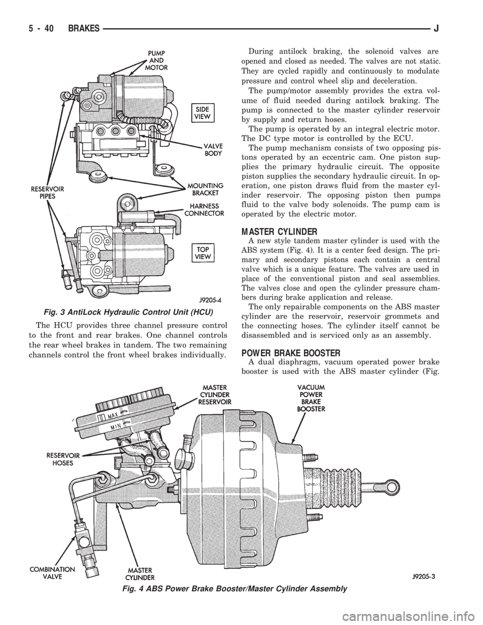
The HCU provides three channel pressure control
to the front and rear brakes. One channel controls
the rear wheel brakes in tandem. The two remaining
channels control the front wheel brakes individually.
During antilock braking, the solenoid valves are
opened and closed as needed. The valves are not static.
They are cycled rapidly and continuously to modulate
pressure and control wheel slip and deceleration.
The pump/motor assembly provides the extra vol-
ume of fluid needed during antilock braking. The
pump is connected to the master cylinder reservoir
by supply and return hoses.
The pump is operated by an integral electric motor.
The DC type motor is controlled by the ECU.
The pump mechanism consists of two opposing pis-
tons operated by an eccentric cam. One piston sup-
plies the primary hydraulic circuit. The opposite
piston supplies the secondary hydraulic circuit. In op-
eration, one piston draws fluid from the master cyl-
inder reservoir. The opposing piston then pumps
fluid to the valve body solenoids. The pump cam is
operated by the electric motor.
MASTER CYLINDER
A new style tandem master cylinder is used with the
ABS system (Fig. 4). It is a center feed design. The pri-
mary and secondary pistons each contain a central
valve which is a unique feature. The valves are used in
place of the conventional piston and seal assemblies.
The valves close and open the cylinder pressure cham-
bers during brake application and release.
The only repairable components on the ABS master
cylinder are the reservoir, reservoir grommets and
the connecting hoses. The cylinder itself cannot be
disassembled and is serviced only as an assembly.
POWER BRAKE BOOSTER
A dual diaphragm, vacuum operated power brake
booster is used with the ABS master cylinder (Fig.
Fig. 3 AntiLock Hydraulic Control Unit (HCU)
Fig. 4 ABS Power Brake Booster/Master Cylinder Assembly
5 - 40 BRAKESJ
Page 191 of 1784
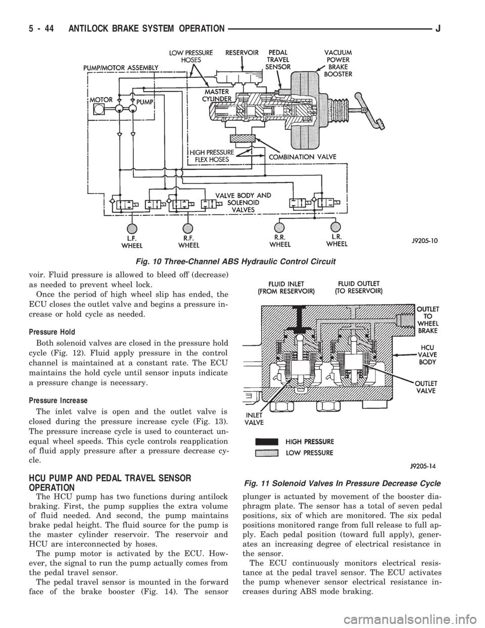
voir. Fluid pressure is allowed to bleed off (decrease)
as needed to prevent wheel lock.
Once the period of high wheel slip has ended, the
ECU closes the outlet valve and begins a pressure in-
crease or hold cycle as needed.
Pressure Hold
Both solenoid valves are closed in the pressure hold
cycle (Fig. 12). Fluid apply pressure in the control
channel is maintained at a constant rate. The ECU
maintains the hold cycle until sensor inputs indicate
a pressure change is necessary.
Pressure Increase
The inlet valve is open and the outlet valve is
closed during the pressure increase cycle (Fig. 13).
The pressure increase cycle is used to counteract un-
equal wheel speeds. This cycle controls reapplication
of fluid apply pressure after a pressure decrease cy-
cle.
HCU PUMP AND PEDAL TRAVEL SENSOR
OPERATION
The HCU pump has two functions during antilock
braking. First, the pump supplies the extra volume
of fluid needed. And second, the pump maintains
brake pedal height. The fluid source for the pump is
the master cylinder reservoir. The reservoir and
HCU are interconnected by hoses.
The pump motor is activated by the ECU. How-
ever, the signal to run the pump actually comes from
the pedal travel sensor.
The pedal travel sensor is mounted in the forward
face of the brake booster (Fig. 14). The sensorplunger is actuated by movement of the booster dia-
phragm plate. The sensor has a total of seven pedal
positions, six of which are monitored. The six pedal
positions monitored range from full release to full ap-
ply. Each pedal position (toward full apply), gener-
ates an increasing degree of electrical resistance in
the sensor.
The ECU continuously monitors electrical resis-
tance at the pedal travel sensor. The ECU activates
the pump whenever sensor electrical resistance in-
creases during ABS mode braking.
Fig. 10 Three-Channel ABS Hydraulic Control Circuit
Fig. 11 Solenoid Valves In Pressure Decrease Cycle
5 - 44 ANTILOCK BRAKE SYSTEM OPERATIONJ
Page 194 of 1784
ABS COMPONENT SERVICE
INDEX
page page
Acceleration Sensor Installation.............. 52
Acceleration Sensor Removal............... 52
Combination Valve ReplacementÐXJ......... 55
Combination Valve ReplacementÐYJ......... 55
Component Serviceability................... 47
Correct Fluid Level....................... 48
ECU ReplacementÐXJ.................... 53
ECU ReplacementÐYJ.................... 53
Front Wheel Sensor Installation.............. 49
Front Wheel Sensor Removal............... 49
HCU InstallationÐXJ...................... 54
HCU InstallationÐYJ...................... 54HCU RemovalÐXJ....................... 53
HCU RemovalÐYJ....................... 54
Importance of Clean Brake Fluid............. 48
Master Cylinder Installation................. 50
Master Cylinder Removal.................. 50
Pedal Travel Sensor Service................ 51
Power Brake Booster Installation............. 51
Power Brake Booster Removal.............. 51
Rear Wheel Sensor Installation.............. 50
Rear Wheel Sensor Removal............... 49
Recommended Brake Fluid................. 48
Wheel Sensor Air Gap Adjustment........... 49
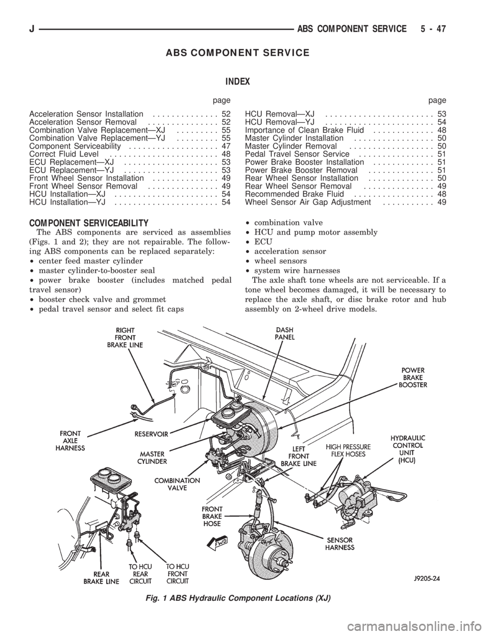
COMPONENT SERVICEABILITY
The ABS components are serviced as assemblies
(Figs. 1 and 2); they are not repairable. The follow-
ing ABS components can be replaced separately:
²center feed master cylinder
²master cylinder-to-booster seal
²power brake booster (includes matched pedal
travel sensor)
²booster check valve and grommet
²pedal travel sensor and select fit caps²combination valve
²HCU and pump motor assembly
²ECU
²acceleration sensor
²wheel sensors
²system wire harnesses
The axle shaft tone wheels are not serviceable. If a
tone wheel becomes damaged, it will be necessary to
replace the axle shaft, or disc brake rotor and hub
assembly on 2-wheel drive models.
Fig. 1 ABS Hydraulic Component Locations (XJ)
JABS COMPONENT SERVICE 5 - 47
Page 216 of 1784
CLUTCH
CONTENTS
page page
CLUTCH DIAGNOSIS..................... 3
CLUTCH SERVICE...................... 10GENERAL INFORMATION.................. 1
GENERAL INFORMATION
INDEX
page page
Clutch Component Lubrication................ 1
Clutch Components........................ 1Clutch Linkage Fluid....................... 1
Clutch Operation.......................... 2
CLUTCH COMPONENTS
MECHANICAL COMPONENTS
The clutch mechanism in XJ/YJ models with man-
ual transmission consists of a single, dry-type clutch
disc and a diaphragm style clutch cover. A hydraulic
linkage is used to operate the clutch disc and cover.
The transmission input shaft is supported in the
crankshaft by a bearing. A sleeve type release bear-
ing is used to engage and disengage the clutch cover
pressure plate.
The release bearing is operated by a release fork in
the clutch housing. The fork pivots on a ball stud
mounted inside the housing. The release fork is actu-
ated by a hydraulic slave cylinder mounted in the
housing. The slave cylinder is operated by a clutch
master cylinder mounted on the dash panel. The cyl-
inder push rod is connected to the clutch pedal.
The clutch disc has cushion springs in the disc hub.
The clutch disc facing is riveted to the hub. The fac-
ing is made from a non-asbestos material. The clutch
cover pressure plate is a diaphragm type with a one-
piece spring and multiple release fingers. The pres-
sure plate release fingers are preset during
manufacture and are not adjustable.
HYDRAULIC LINKAGE COMPONENTS
The hydraulic linkage consists of a clutch master
cylinder with integral reservoir, a clutch slave cylin-
der and an interconnecting fluid line.
The clutch master cylinder push rod is connected to
the clutch pedal. The slave cylinder push rod is con-
nected to the clutch release fork. The master cylinder
is mounted on the driver side of the dash panel ad-jacent to the brake master cylinder and booster as-
sembly. This positioning is similar for both left and
right hand drive models.
CLUTCH LINKAGE FLUID
The integral clutch master cylinder reservoir, slave
cylinder and fluid lines are prefilled with fluid prior
to assembly operations.
The hydraulic system should not require additional
fluid under normal circumstances. In fact,the reser-
voir fluid level will actually increase as normal
clutch wear occurs. For this reason, it is impor-
tant to avoid overfilling, or removing fluid from
the reservoir.
If inspection or diagnosis indicates additional fluid
may be needed, use Mopar brake fluid, or an equiv-
alent meeting standards SAE J1703 and DOT 3. Do
not use any other type of fluid.
CLUTCH COMPONENT LUBRICATION
Proper clutch component lubrication is important
to satisfactory operation. Using the correct lubricant
and not overlubricating are equally important. Apply
recommended lubricant sparingly to avoid disc and
pressure plate contamination.
Clutch and transmission components requiring lu-
brication are:
²pilot bearing
²release lever pivot ball stud
²release lever contact surfaces
²release bearing bore
²clutch disc hub splines
²clutch pedal pivot shaft bore
²clutch pedal bushings
²input shaft splines
JCLUTCH 6 - 1