Page 371 of 521
15.11 MOTORS & SOLENOIDS ~
5.1 1.1 General
Description
Electrical
I# b
Fig. 1 Motors & Solenoids
-
1695
Fig. 1 shows a plan view of all motors located inside the trunk, the passenger compartment and the engine bay. The
motors drive various devices to perform certain functions such wipe / wash operations, window lift operations, seat
operations etc.
In order to carry out remove and refit operations, the annotated illustration is to be read in conjunction with the table
shown on the following page. This lists
all the motors and solenoids.
Some motors can be accessed by removing the various trims, the carpet, or carpet sections, other can be located
through carrying out
a visual inspection around the engine bay, the cab and the trunk.
To avoid any accidents such as electric shocks, always disconnect the battery negative lead from the battery negative
terminal before disconnecting any of the listed cables.
Issue 1 August 1994 30 X300 VSM
Page 465 of 521

Body Systems & Body Repair
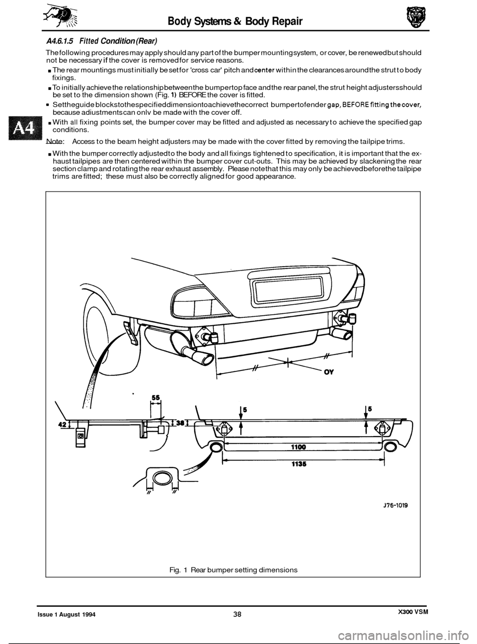
A4.6.1.5 Fitted Condition (Rear)
The following procedures may apply should any part of the bumper mounting system, or cover, be renewed but should
not be necessary if the cover is removed for service reasons.
. The rear mountings must initially be set for 'cross car' pitch and center within the clearances around the strut to body
. To initially achieve the relationship between the bumpertop face and the rear panel, the strut height adjustersshould
9 Settheguide blockstothespecified dimensiontoachievethecorrect bumpertofender gap,BEFOREfittingthecover,
fixings.
be set to the dimension shown (Fig.
1) BEFORE the cover is fitted.
because adiustments can onlv be made with the cover
off.
. With all fixing points set, the bumper cover may be fitted and adjusted as necessary to achieve the specified gap
- Note:
conditions.
Access to the beam height adjusters may be made with the cover fitted by removing the tailpipe trims.
. With the bumper correctly adjusted to the body and all fixings tightened to specification, it is important that the ex-
haust tailpipes are then centered within the bumper cover cut-outs. This may be achieved by slackening the rear
section clamp and rotating the rear exhaust assembly. Please note that this may only be achieved before the tailpipe
trims are fitted; these must also be correctly aligned for good appearance.
J76-1019
Fig. 1 Rear bumper setting dimensions
X300 VSM Issue 1 August 1994 38
Page 470 of 521

0 Gaps should be uniform around body panel contours.
0 Gaps must be parallel to within Imm in a 400mm linear measurement.
0 Panels which are centered between 2 (two) adjacent panels must have equal gaps either side; there are excep- tions to this, please refer to the appropriate specification.
0 Gaps between adjacent panels or components must not expose harnesses, labels, brackets or visually poor
joint or assembly conditions.
Particular areas of concern:
Fuel filler flap.
Trunk
lid to fenders and saddle.
Hood to fenders, grille and headlamps.
Sliding roof panel to the main roof panel.
Door gaps at fender, 'B
/ C' pillar, roof drip rail and rocker panel.
Bumper cover to fender and cross car assemblies (see section A4.6.1.4
& A4.6.1.5).
m: Please note thatthe sliding roof panel clearances are specified WITHOUT the edge seal, referto the illustration
on the following page.
A4.7.1.3 Criteria - A1;gnment
0 Panels must be correctly 'profiled' to maintain cosmetic appearance, pressure on seals and control wind noise.
Particular areas of concern:
Hood to fender.
Trunk
lid to fender and saddle.
Door to aperture.
Door to fender and adjacent door.
The relationship of the sliding roof panel leading and trailing edges to the main roof panel.
A4.7.1.4 Criteria - Exterior Fitments
Particular areas of concewn:
0 Bezels, trims and lamps must be centered within apertures and have equal clearances with adjacent panels.
Headlamp to hood, fender and trim panel.
Exhaust
tailpipe trim to bumper cover cut-out.
Rear lamp assembly to trunk lid, fender and bumper cover
trim.
Feature lines fender to door and door to door (this includes body side mouldings).
A4.7.1.5 Exterior clearances and alignments, Illustrations
Specifications for gaps and profile may be found on the illustrations on the following three pages.
A4.7.1
A4.7.1.1
Introduction
Wherever a panel, closure or component is renewed, refitted or reset, the factory specifications for clearance (gap) and
alignment (profile) MUST be attained.
There is no distinction between the importance of visual and operational characteristics; all conditions must be satis
- fied so that the vehicle looks and operates to the satisfaction of both design intent and the customer.
BODY EX7ERlOR CLEARANCES AND ALIGNMENTS
A4.7.1.2 Criteria
- Clearances
Issue 1 August 1994 43 X300 VSM