1994 JAGUAR XJ6 ESP
[x] Cancel search: ESPPage 81 of 327

Climate Control Systems
14.2.16 Servo Motor Control
The system incorporates several servo motors which direct the flow of air through the air conditioning system. The
motors are driven by A / CCM signals in either a clockwise or anti-clockwise direction.
Servo motor position is monitored via
a feedback potentiometer situated within the motor housing.
The system servos comprise:
o RH and LH Air intake servos (Fresh / Recirc.).
0 Centre vent servo.
o Defrost (screen vent) servo.
0 Footservo.
0 Cool air by-pass servo.
14.2.17 Blower Motor Control
The A/ CCM controls two blower motors, delivering airflow
to the evaporator / heater unit, at variable fan speeds. The
blower motors are regulated by power transistor modules
which provide linear variation of blower speed; the blower
speed
is increased or reduced progressively in response to
vehicle speed, minimising the ram effect of forward motion.
The blower motors are inhibited when engine coolant tem
- perature is below 30°C and heating is requested.
14.2.18 Differential Control
The differential control is mounted on the facia centre vent. It is used to control the temperature difference between the
upper and lower outlets. Fig.
1 Servo
Motor
14.2.19 Heated Rear Window, Door Mirrors and Front Screen
The Heated Rear Window (HRW) function can only be activated with the ignition on and the engine running. Operation of the HRW switch operates the status condition LED on the control panel and switches on the HRWfor approximately 21 minutes. Selection of the HRW also operates the door mirror heaters for approximately 11 minutes. The operation
can be cancelled by switch re-selection or ignition off. System off does not cancel the HRW operation.
The Heated Front Screen
(HFS) function can only be activated with the ignition on and the engine running, and either
‘defrost’ mode selected or HFS selected. Each half, left and right hand split, switches on for approx. 6.5 minutes. The
operation can be cancelled by switch re-selection or ignition off. System off does not cancel the HFS operation.
0
0
Issue 1 August 1994 6 X300 EDM
Page 92 of 327

Climate Control Systems
14.7.6 FaulfCode21
Solar Sensor
0 Sensor, harness or A / CCM open circuit.
0 Sensor, harness or A / CCM short circuit to ground.
The sensor provides a linear output response signal to
pin 35 (16-way connector) A/ CCM; the output ranges from 0 to 5 volts, the voltage will drop as light intensity increases.
A resistance check can be carried out on the sensor and should conform with the figures below:
With no light on the sensor, the resistance should read approximately 15
kL2.
With increasing light intensity, the resistance should decrease from 15 kQ.
Inspect the sensor harness for open circuit or short circuit to ground. Rectify as necessary.
If the sensor and harness appear correct, suspect the A/ CCM.
14.7.7 Fadf Code 22
Compressor lock Signal
(12 cy/. vehicles only)
0 Sensor, harness or A / CCM open circuit.
0 Sensor, harness or A/ CCM short circuit to ground.
The compressor lock sensor provides an
a.c. signal proportional to engine speed. As engine speed increases the a.c. signal voltage value will increase.
A voltage checkcan be carried out on the sensor and should read approximately 0.5V a.c. whilst the compressor is ON and OV whilst the compressor is OFF, measured between pin 26 (12-way connector) and pin 19 (22-way connector) A
/ C CM.
If the reading is OV whilst the compressor is ON, suspect the sensor or the sensor harness (open circuit or short circuit
to ground).
Check the resistance between pins 1 and 2 of the compressor lock sensor, value should be
190a & 20%.
If the resistance measured falls outside the limits, renew the compressor lock sensor.
Inspect the sensor harness for open circuit or short circuit to ground. Rectify as necessary.
If the sensor and harness appear correct, suspect the AI CCM.
X300 EDM 17 Issue 1 August 1994
Page 94 of 327

Climate Control Systems
Position
Closed Open
Closed Open
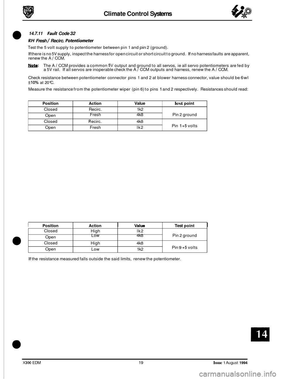
14.7.11 Fault Code 32
RH Fresh / Recirc. Pofenfiomefer
Test the 5 volt supply to potentiometer between pin 1 and pin 2 (ground).
If there is no 5V supply, inspect the harness for open circuit or short circuit to ground. If no harness faults are apparent,
renew the A 1 CCM.
W: The A / CCM provides a common 5V output and ground to all servos, ie all servo potentiometers are fed by
a 5V rail. If all servos are inoperable check the A 1 CCM outputs and harness, renew the A I CCM.
Check resistance between potentiometer connector pins 1 and 2 at blower harness connector, value should be
6wl
f10% at 20°C.
Measure the resistance from the potentiometer wiper (pin
6) to pins 1 and 2 respectively. Resistances should read:
Action Value lest point
Recirc. 1 k2
Fresh 4k8 Pin 2 ground
R eci rc. 4k8
Pin 1 +5 volts
Fresh lk2
Closed Open
Closed
Open
e
I Position I Action I Valw 1 Test point I
High lk2
Low 4k8 Pin 2 ground
High 4k8
Pin
9 +5 volts
Low 1 k2
If the resistance measured falls outside the said limits, renew the potentiometer.
X300 EDM 19 Issue 1 August 1994
Page 95 of 327

Climate Control Systems
Position
Closed
Open
Closed
ODen
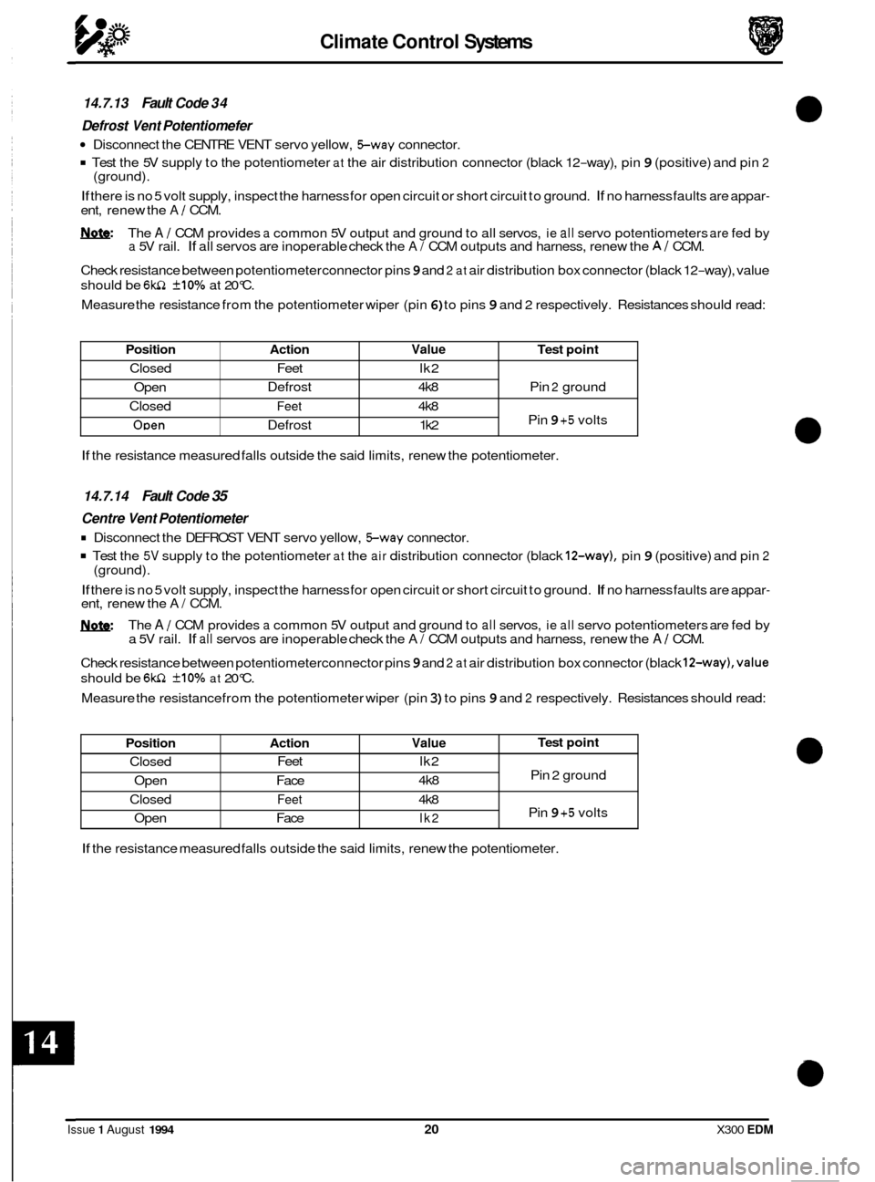
14.7.13 Fault Code 34
Defrost
Vent Potentiomefer
Disconnect the CENTRE VENT servo yellow, Sway connector.
Test the 5V supply to the potentiometer at the air distribution connector (black 12-way), pin 9 (positive) and pin 2
If there is no 5 volt supply, inspect the harness for open circuit or short circuit to ground. If no harness faults are appar-
ent, renew the A / CCM.
&&: The A / CCM provides a common 5V output and ground to all servos, ie all servo potentiometers are fed by a 5V rail. If all servos are inoperable check the A/ CCM outputs and harness, renew the AI CCM.
Check resistance between potentiometer connector pins
9 and 2 at air distribution box connector (black 12-way), value
should be
6w1 +10% at 20°C.
Measure the resistance from the potentiometer wiper (pin
6) to pins 9 and 2 respectively. Resistances should read:
(ground).
Action Value Test
point
Defrost 4k8 Pin 2 ground
Feet 4k8
Pin 9 +5 volts
Defrost 1 k2
Feet
lk2
Position Action Value
Closed Feet
lk2
4k8
Open Face
Closed
Feet 4k8
Open Face
lk2
If the resistance measured falls outside the said limits, renew the potentiometer.
Test point
Pin 2 ground
Pin
9 +5 volts
14.7.14 Fault Code 35
Centre Vent Potentiometer
Disconnect the DEFROST VENT servo yellow, Sway connector.
Test the 5V supply to the potentiometer at the air distribution connector (black 12-way), pin 9 (positive) and pin 2
If there is no 5 volt supply, inspect the harness for open circuit or short circuit to ground. If no harness faults are appar- ent, renew the A/ CCM.
The
A / CCM provides a common 5V output and ground to all servos, ie all servo potentiometers are fed by
a 5V rail. If all servos are inoperable check the A/ CCM outputs and harness, renew the A / CCM.
Check resistance between potentiometerconnector pins
9 and 2 at air distribution box connector (black 12-way),value
should be 6wZ +10% at 20°C.
Measure the resistance from the potentiometer wiper (pin
3) to pins 9 and 2 respectively. Resistances should read:
(ground).
If the
resistance measured falls outside the said limits, renew the potentiometer.
Issue 1 August 1994 20 X300 EDM
Page 96 of 327

Climate Control Systems
Position Action Value Test point
Closed Face 1 k2
Open Foot
4k8
Closed Face
4k8
Open Foot
1 k2
Pin 2 ground
Pin
9 +5 volts
14.7.15 Fault Code 36
Foot Vent
Potentiometer
Disconnect the COOL AIR BYPASS yellow, Sway connector.
. Test the 5V supply to the potentiometer at the main unit, pin 9 (positive) and pin 2 (ground).
If there is no 5 volt supply, inspect the harness for open circuit or short circuit to ground. If no harness faults are appar- ent, renew the A I CCM.
&&: The A I CCM provides a common 5V output and ground to all servos, ie all servo potentiometers are fed by a 5V rail. If all servos are inoperable check the A 1 CCM outputs and harness, renew the A 1 CCM.
Check resistance between potentiometer connector pins9 and
2 at blower motor connector, value should be 6kn +10%
at 20°C.
Measure the resistance from the potentiometer wiper (pin
6) to pins 9 and 2 respectively. Resistances should read:
14.7.16 Fault Code 4 1
1 H Fresh / Recirc. Motor
The resistance between pins 1 and 3, servo unit Sway connector, should read 4.8 - 7.2 kn.
If the resistance is outside of the set limits, renew the servo unit.
The motor operation can be checked by applying battery voltage to pin
5, motor %way connector, and ground to pin 4 of the connector. The motor arm should rotate smoothly in a clockwise direction. Renew the motor if the arm does
not rotate smoothly.
Apply battery voltage to pin
4, servo unit %ay connector, and ground to pin 5. The motor arm should rotate smoothly
in a anti-clockwise direction. Renew the motor if the arm does not rotate smoothly.
Inspect the harness for open circuit or short circuit to ground. Rectify as necessary.
If no harness faults are apparent,
renew the AI CCM.
14.7.17 Fault Code 42
RH Fresh / Recirc. Motor
The resistance between pins 1 and 3, servo unit Sway connector, should read 4.8 - 7.2 kn.
If the resistance is outside of the set limits, renew the servo unit.
The motor operation can be checked by applying battery voltage to pin
5, motor Sway connector, and ground to pin 4 of the connector. The motor arm should rotate smoothly in a clockwise direction. Renew the motor if the arm does
not rotate smoothly.
Apply battery voltage to pin
4, servo unit Sway connector, and ground to pin 5. The motor arm should rotate smoothly
in a anti-clockwise direction. Renew the motor if the arm does not rotate smoothly.
Inspect the harness for open circuit or short circuit to ground. Rectify as necessary.
If no harness faults are apparent,
renew the A I CCM.
21 Issue 1 August 1994
Page 181 of 327

I3 E I ect r ical
15.3.2.5 Throttle Linkage and Bellows
The throttle linkage and bellows are located adjacent to the throttle body (below supercharger, where fitted) on 6cylin-
der vehicles, or centrally below the injector cover on 12 cylinder vehicles. The bellows expand I contract according
to the pressure drop created by the pump I control valve module, causing the linkage to act upon the throttle body,
controlling vehicle speed.
15.3.2.6
The brake and clutch pedal switches are mounted below the relevant foot pedals. Operation of a pedal, causes subse- quent switch operation, either interrupting the+12Vsupplytothe pneumaticcircuit, orsignalling tothe SC CMto disen- gage speed control, causing the dump valve to open and vent the system, returning speed control to the driver.
Brake and Clutch Pedal Switches
15.3.2.7 Speed Control Selection Switches
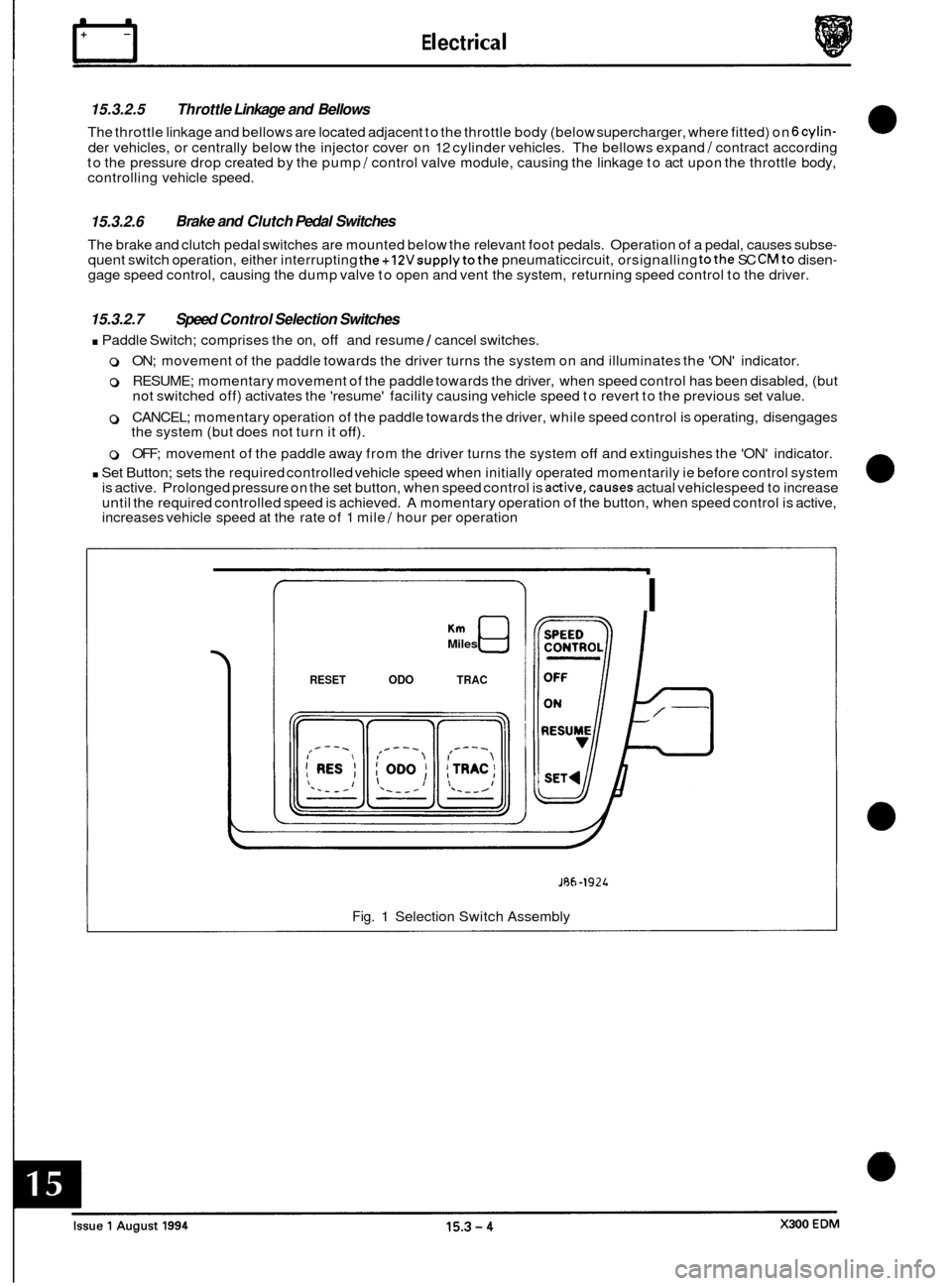
. Paddle Switch; comprises the on, off and resume 1 cancel switches.
0 ON; movement of the paddle towards the driver turns the system on and illuminates the 'ON' indicator.
0 RESUME; momentary movement of the paddle towards the driver, when speed control has been disabled, (but
not switched off) activates the 'resume' facility causing vehicle speed to revert to the previous set value.
0 CANCEL; momentary operation of the paddle towards the driver, while speed control is operating, disengages
the system (but does not turn it off).
0 OFF; movement of the paddle away from the driver turns the system off and extinguishes the 'ON' indicator.
. Set Button; sets the required controlled vehicle speed when initially operated momentarily ie before control system
is active. Prolonged pressure on the set button, when speed control is active,causes actual vehiclespeed to increase
until the required controlled speed is achieved. A momentary operation of the button, when speed control is active,
increases vehicle speed at the rate of 1 mile
/ hour per operation
Miles
RESET ODO TRAC
I
JRh-1924
Fig. 1 Selection Switch Assembly
Page 187 of 327

rl E I ect r ica I
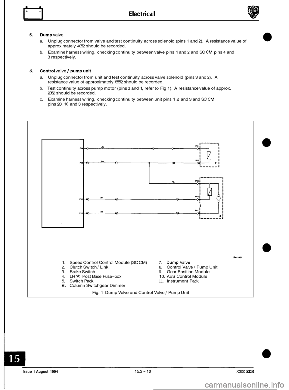
5. Dump valve
a.
b.
Unplug connector from valve and test continuity across solenoid (pins 1 and 2). A resistance value of
approximately 4052 should be recorded.
Examine harness wiring, checking continuity between valve pins 1 and
2 and SC CM pins 4 and
3 respectively.
6. Control valve / pump unit
a. Unplug connector from unit and test continuity across valve solenoid (pins 3 and 2). A
resistance value of approximately 8552 should be recorded.
b. Test continuity across pump motor (pins 3 and 1, refer to Fig 1). A resistance value of approx.
2052 should be recorded.
c. Examine harness wiring, checking continuity between unit pins 1,2 and 3 and SC
CM
pins 20, 10 and 3 respectively.
I Ii
1
1. Speed Control Control Module (SC CM) 7. Dumpvalve
2. Clutch Switch / Link 8. Control Valve / Pump Unit
3. Brake Switch 9. Gear Position Module
4. LH 'A' Post Base Fuse-box 10. ABS Control Module
5. Switch Pack
11. Instrument Pack 6. Column Switchgear Dimmer
Fig. 1 Dump Valve and Control Valve
/ Pump Unit
0
0
0
0
Issue 1 August 1994 15.3 - 10 X300 EDM
Page 200 of 327

15.4.1.4 Remote Recall
Remote activation of memory positions 1 and 2 can be achieved using the key fob transmitters (one per set of keys).
lfthe vehicle is unlocked using the remote transmitter the stored driving position will be adopted automatically. If the
vehicle is unlocked using the remote transmitter and an exit position is already set the corresponding entry position
will be adopted until the ignition key is inserted, the stored driving position will then be restored. 0 ~
15.4.1.5
Reverse Mirror Dip
On selection of reverse gear and operation of the mirror toggle switch downwards, the passenger side rear view mirror
will automatically tilt downwards to assist reverse parking. Upward adjustment disables reverse dip, a further down- ward adjustment when still in reverse gear reinstates reverse dip. The mirror will return to normal position when any
other gear position is selected.
15.4.2 SYSTEM COMPONENTS
15.4.2.1 Seats
- Driver and Passenger
The driver and passenger seat adjustment systems comprises the following components:
o Fore / aft motor
o Front raise / lower motor
o Rear raise / lower motor
0 Squab recline motor
0 Headrest motor
0 Lumbarpump
0 Squab heater
0 Inner cushion heater
0 Outer cushion heater
0 Heater thermostat
0 Switch pack
o Seat Control Module (SCM)
o Wiring harness
15.4.2.2 Motors
The five seat position adjustment motors are located below the seat cushions (horizontal and vertical adjustment) and
behind the squab (recline and headrest adjustment). Each motor unit incorporates a potentiometer which provides
directional movement position control via feedbackvoltage variations to the SCM. Positional variations are activated
by the SCM in response to signals from switches mounted on the seat switch pack.
15.4.2.3 Lumbar Pump
The lumbar pump, located behind the seat squab allows adjustment of seat rigidity by increasing/decreasing air pres- sure in the lumbar pad. The pump motor is controlled from a switch on theseat switch pack and governed by an in-line
pressure switch.
A solenoid valve is used to regulate air flow to the lumbar pad.
15.4.2.4 Heaters and Thermostats
The two cushion heaters and squab heater are regulated by a single in-line thermostat and operated by a switch
mounted on thecenter console switch pack. Operation of this switch causesthe Body Processor Unit (BPU) to energize a timed input to SCM (for 11 minute f 1) which in turn causes SCM to energize the heater supply. The supply will
remain on until timed out, although the heater circuit will be broken by the thermostat if the set temperature is ex- ceeded.
Note: Heatingcan only occur when the ignition switch is position I1 and the ambient temperature is belowthe thermo- stat pre-set value of 26°C.
X300 EDM 15.4 - 3 Issue 1 August 1994