Page 1380 of 1413

Sensor Inspection
CAUTION: Tak€ €xtra care whon painting or doing
body work in the ar€a bslow th6 dalhboard.
Avoid dirost exposure ot lh6 sonsors or wiring to hestguns, wolding, or spraying equipmont.
Di3connact both the nogativo and po3itivo b!ftery
cable3.
Connsct tho short conneclor(s) before working
bslow the da3hboard or nsar lhe dash sen3o.3.
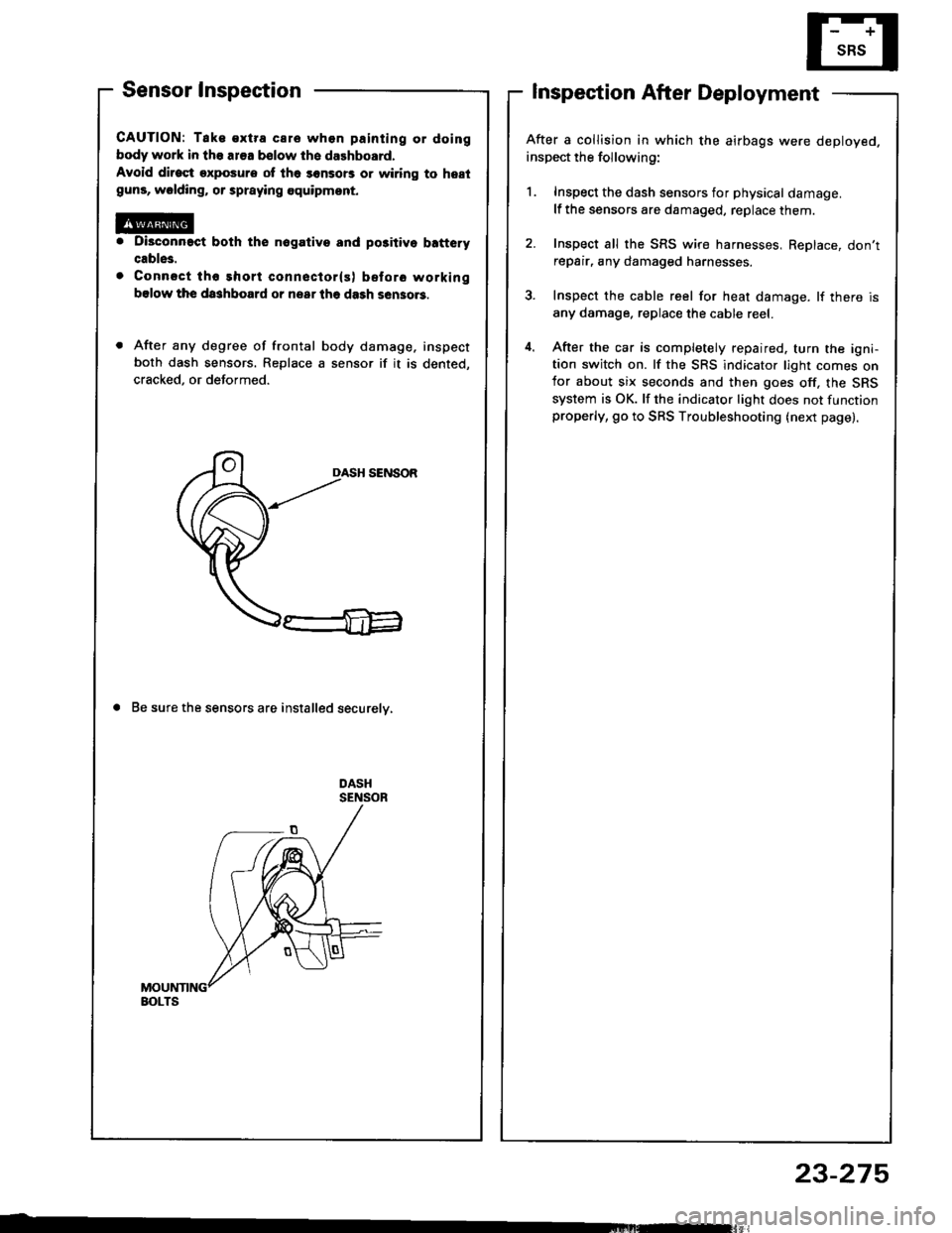
After any degree of frontal body damage, inspect
both dash sensors. Replace a sensor if it is dented,
cracked, or deformed.
DASH SENSOR
a Be sure the sensors are installed securelv,
Inspection After Deployment
After a collision in which the airbags were deployed.
inspect the following:
1. Inspect the dash sensors for physical damage.
lf the sensors are damaged, replace them.
2. Inspect all the SRS wire harnesses, ReDlace, don'trepair, any damaged harnesses.
3. Inspect the cable reel for heat damage. lf there is
any damage. replace the cable reel.
4. After the car is completely repaired. turn the igni-tion switch on. lf the SRS indicator light comes onfor about six seconds and then goes off, the SRS
system is OK. lf the indicator light does not functionproperly, go to SRS Troubleshooting (next page).
BOLTS
23-275
Page 1402 of 1413
CAUTION: Bo 3uro to in3tsll tho SRS wiring so that it isnot pinchod or intoforing with other car parts.
4. Install the new airbag(s):
Driver's Sido: Place the driver's airbag assembly inthe steering wheel, and secure it with new TORX@bolts.
TORXC BOLT9.8 N'm 11.0 kgt m.7.2lbf.ftl Replace.Uio a TORXO T30 bit
TORXO BOLI9,8 N'm l'1.0 kgf.m,7.2lbtftl Replaco.Us. . TORX6 T30 bit
Front Pa$aogsr's Sid€:
. Place the front passenger's airbag assembly in thedashboard.
Loosely install all four mounting nuts.
Tighten the upper two nuts first, then the lowsr twonuts. Adjust the lower mounting bracket if necessarV.
FRONT PASSENGER'SAIRBAGASSEMALY
UPPERMOUNTING NUTS
LOWERMOUNTING NUTS9.8 N.m (1.0lgtm, t.2lbtftlReolace.
CONNECTORIREDI
{cont'd)
23-297
Page 1405 of 1413

Supplemental Restraint System (SRSI
Airbag Assembly Disposal (cont'd)
Connect a l2 volt batterv to the tool:
. lf the green light on the tool comes on, th€
airbag igniter circuit is d€fective and cannot
deploy the airbag. Go to Dsmag€d Airbag
Special Procedure.
. lf the red light on the tool comes on, the airbag is
ready to be deployed.
Push the tool's deployment switch. Th6 sirbag
should deploy (deployment is both highly audible
and visibls - a loud noise and raDid inflation of the
bag, followed by slow deflationl.
. lf audible/visible deploym€nt happsns and the
green light on the tool comes on, continus with
this Drocedure.
. lf the airbag doesn't deploy, yet the green light
comes ON, its igniter is dofectiv€. Go to
Damaged Airbag Special Procedure.
@ During deploym€nt, the airbsg assom-
bly can become hot enough to burn you. Wait thirty
minutes after deployment beforo touching the
assemblv.
Dispose of the complete airbag sssembly. No pan
of it can be reused. Place it in I sturdy plastic bag
and seal it securelv.
CAUTION:
Woar a taco shiold lnd glov.s whon hlndling !
doploy.d airbag.
Waeh your hands and rin3a tham wall with
wslor aftor handling r deploycd !irb!g.
23-300
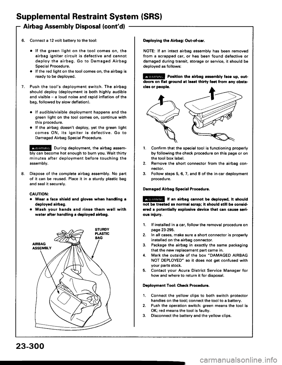
Doploying the Airbag: Out-ot{!r.
NOTE: lf an intsct airbag assembly has been removed
from a scrapped car, or has been found dofective or
damagsd during transit, storage or service, it should bs
dsployed as follows:
@ Porition th6 lirbrg rr:.mbly t.ce up, out-
doo6 on flat ground !t lorrt thirty foot from rny ob3t..
clar or pcoplo.
1. Confirm that the special tool is functioning properly
by following the check procedure on this page or on
the tool box label.
2. Remove the short connector from the airbag con-
nector.
3. Folfow steps 5,6,7, and 8 of the in-car deployment
orocequre.
Dlmlged Airbsg Sp.ci8l Procoduro.
E!@ f rn lirbag crnnot be deploy.d, it rhould
not br trcltcd !s normll scrrp; ii 3hould still bc comid-
ercd a potantillly oxplolivr dcvicc thli cln c!u3a 3ari-
ou3 iniury.
1. lf instslled in a car, follow the removal procedure on
page 23-295.
2. In all cases, make sure a short connector is properly
installed on the airbag conn€ctor.
3. Package the airbag in sxacily the same packaging
that the now replacement part cama in.i[. Mark the outside 0f the box "DAMAGED AIRBAG
NOT OEPLOYED" so it does not get confused with
your parts stock.
5. Contact your Acura District Service Manager for
how and where to return it for disoosal.
Dcploymont Tool: Chcck Procedure.
1. Connect the yellow clips to both switch protector
handles on the tool; connect the tool to a battery.
2. Push th€ operation switch: green means the tool is
OK; red means the tool is faulty.
3. Disconnect the battery and the yellow clips.
Page 1411 of 1413

Supplemental Restraint System (SRSI
Dash Sensor Replacement (cont'dl
CAUTION:
. Be 3ure to install the harness wires so that theY ars
not pinchcd or interfering with othor car parte.
o Carefully inspest the dash sensors lor signs of boing
dropped or improperly handled,3uch as dents,
cracks or dsformation.
. For the SRS to lunction propotly, ths right and lsft
sensors must be installsd on the propor sidos.
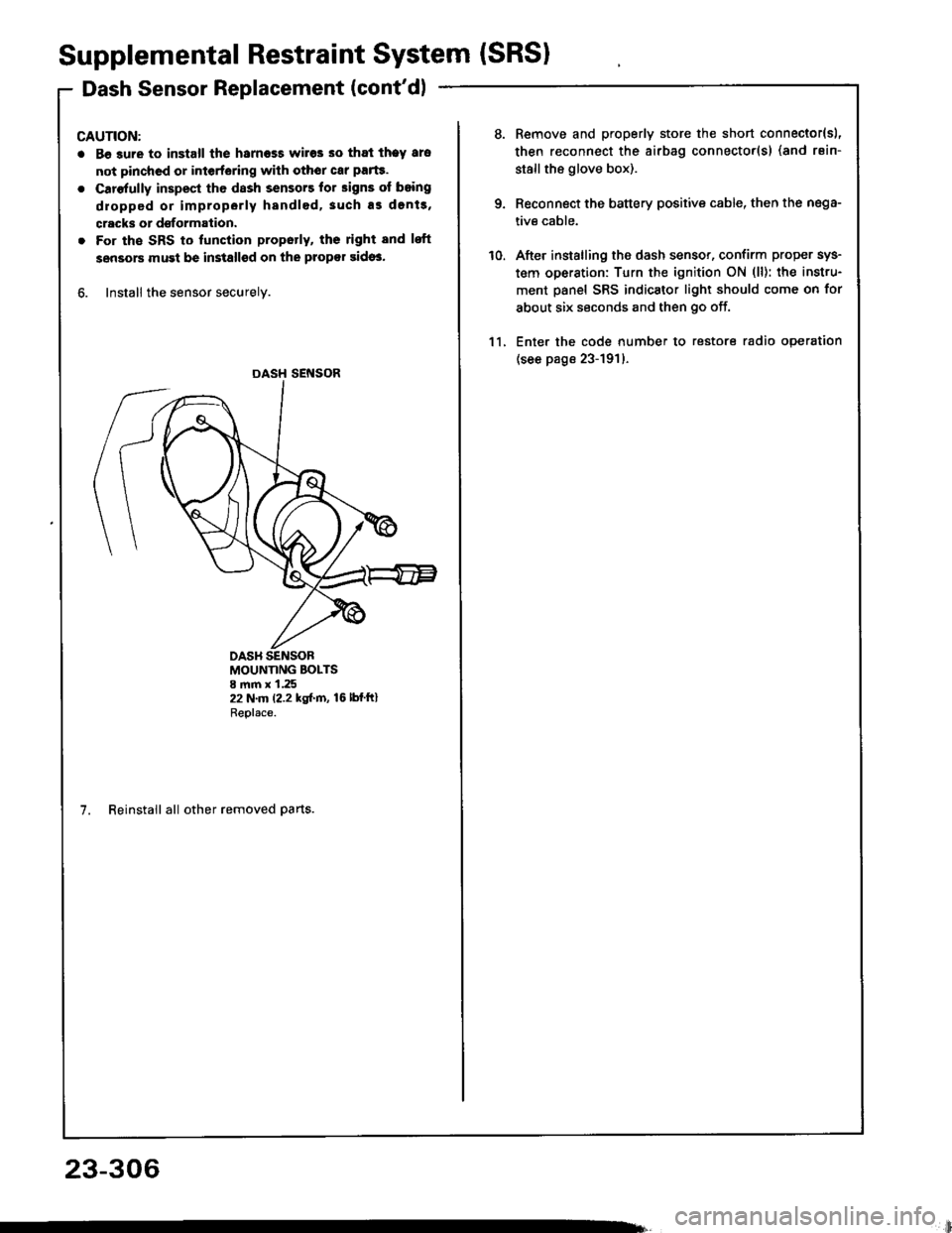
6. Install the sensor securely.
DASH SENSOR
MOUNTING BOLTS8 mm x 1.2522 N.m (2.2 kgf.m, 16lbfftlReplace.
7. Reinstall all other removed parts.
23-306
li
10.
Remove and properly store the short connector{sl,
then reconnect the airbag connector(s) (and rsin-
stallthe glove box).
Reconnect the battery positive cable, then the nega-
tive cable.
After installing the dash sensor, confirm proper sys-
tem operation: Turn the ignition ON (ll): the instru-
ment panel SRS indicator light should come on for
about six seconds and then go off.
Enter the code number to restore radio operation
(see page 23-191)-
11.