1994 HONDA INTEGRA fuel
[x] Cancel search: fuelPage 443 of 1413

Number of @indicator light
blinks while
Service Check
Connector is
connected with
the special tool.
@ indicator
lightPossible CauseSymptomRefer to
page
'loBlinksDisconnected engine coolant tempera-
rure (ECT) sensor connector
Short or open in ECT sensor wire
Faulty ECT sensor
Lock-up clutch does not
engage.14-68
1lOFFDisconnected ignition coil connector
Short or open in ignition coil wire
Faulty ignition coil
. Lock-up clutch does not
engage.'t 4-7 0
13Blinks. Shon or open in LT GRN wire between
the D3 terminal and ECM. Faulty barometric pressure {BARO)
sensor
NOTE: The BARO sensor is built into
the ECM
. No specific symptom
appears.
14-7 1
14Blinks. Short of open in FAS {YEL} wire be-
tween the D16 terminal and ECM. Faulty ECM
. Transmission jerks hard
when shitting.
't5OFFDisconnected mainshaft speed sensor
connecror
Short or open in mainshaft speed sen-
sor wire
Faulty mainshaft speed sensor
. Transmission jerks hard
when shifting.
14-75
SymptomProbable CauseRet.page
LQ! indicator light is on steady, not blinking whenever the ignition is on.14-77
[Q3] indicator light does not come on for 2 seconds after ignition is first
turned on.14-78
Lock-up clutch does not have duty operation (ON-OFFI.Check A/C signal with
A/C on.14-80Lock-up clutch does not engage.
Shitt leve. cannot be moved lrom @ position with the brake pedal
depressed.Check brake switch signal,14-41
It the self-diagnosis LQ4 indicator light does not blink, perform an inspection according to the table below.
a lf a customer describes the symptoms for codes 3, (yet the LQ! indicator light is not blinkingl, 6, 1 1 or 15, it will
be necessa.y to recreate the symptom by test driving. and then checking the @ indicator light with the ignition still
oN.
e lt ttre @ indicator light displays codes olher than those listed above or stays lit continuously, the TCM is faulty.. Sometimes the Lqd indicator light and the Malfunction Indicator Lamp (MlL)/Check Engine light may come on simul-taneously. lf so, check the PGM-Fl system according to the numbe. of blinks on the MIL/Check Engine light. thenreset the memory by removing the BACK UP fuse in the unde.-hood fuse/relay box for more than 1O seconds. Drive
the vehicle for several minutes at speed over 30 mph (5O km/h), then recheck the MIL/Check Engine light.
NOTE:
. PGM-FI system
The PGM-Fl system on this model is a sequential multiport fuel injection system.a Disconnecting the BACK UP luse also cancels the radio anti-theft code. preset stations and the clock setting. Get
the fuse so vou can reset them.the customer's code number and make note ot the radio
14-51
Page 1021 of 1413
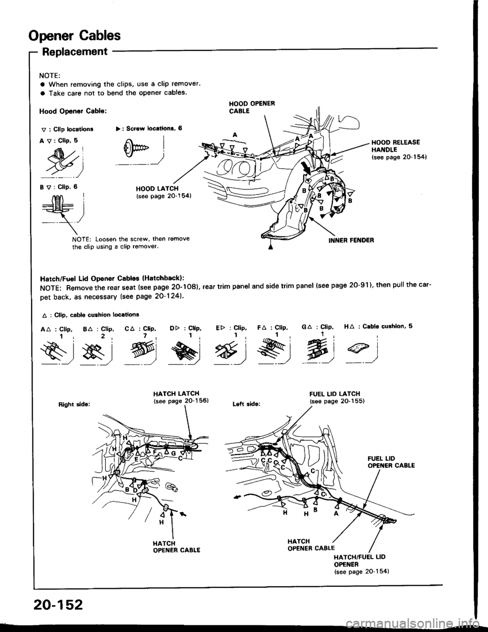
Opener Cables
NOTE:
a When removing the clips, use a clip remover.
a Take care not to bend the opener cables.
Replacement
Hood Opener Cable:
v : Clip location.
Av:CllP,5
M)
HOOD OPENERCABLE
> : Scrow locrtions, 6
Otr" I
:_ _)
HOOD RELEASEHAI{DLE(se€ page 20-1 54)
Bv:Clip.6HOOD LATCH(see page 20"154)E\I____lEt- L:=r
,/- -\-
NOTE: Loosen the screw, then remove
the clip using a clip remover.INNER FENDER
HA : C.bl6 cushlon, 5GA : Clip,
Wt
DD : Cllp, Etr : Cllp,1, I,
e&r @)9)
HATCH LATCH
lsee page 2O-1 56)Loft 3ido:
FUEL LID LATCH
lsse page 2O-155)
Hatch/Fuol Lid Oponer Cabls lHatchback):
NOTE: Remove the rear seat (see page 20-108), rear trim pan€l and side trim panel (see page 2O-91), then pull thecar-
Det back. as necessary lsee page 20-124).
A : Clip, csblo cushion location3
AA : Clip, 8A : Clip, CA : CliP,i r 2, 7,
s-,$, g,
FA : Cllp,
s,l
Right sids:
HATCHOPENER CABLE
HATCH/FUEL LID
OPENER{see page 2O-'l 54)
20-152
HATCH
Page 1022 of 1413
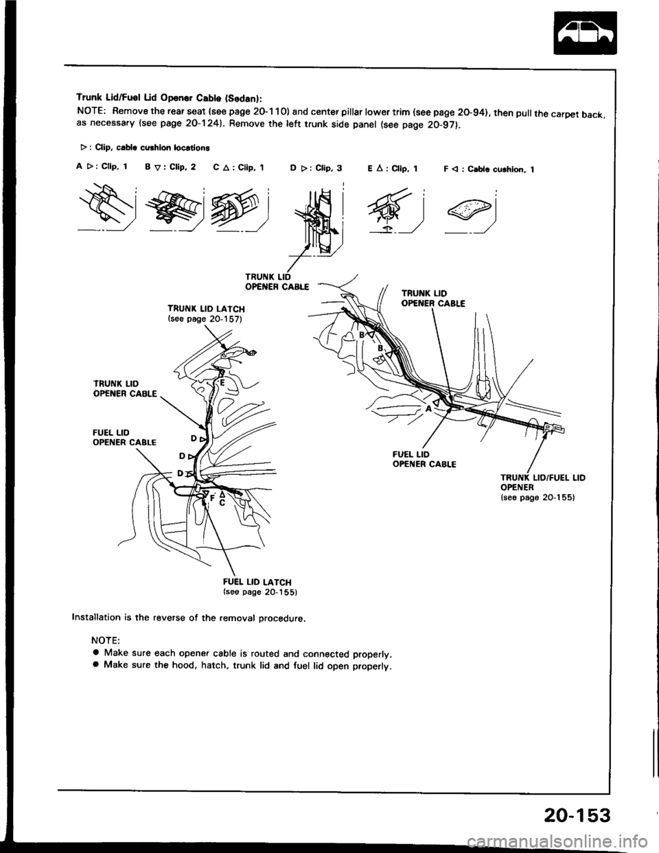
Trunk Lid/Fuol Lid Opan.. Cablo (Sodanl:
NOTE: Remove the rear seat {see page 2O-1 10) and center pillar lowertrim (see page 20-94}, then pullthe carDet back.as necessa.y (see page 2O-1241. Remove rhe left trunk side panel (see page 20-97).
> : CliD, c.bla cu.hion locstlon!
A >: Cllp, 1 BV:Clip,2 C A: Clip,,tD >: Clip,3F < : C.ble culhlon, 1
ws@:
ffi;
7--
TRUITIK LID LAICH(s€e p6ge 20-157)
FUEL LID
FUEI. LID LATCH(soo pago 20_'|55)
Installation is the reverse of the removal orocedure.
NOTE:
a Make sure each opener cable is routed and connected properly.a Make sure the hood, hatch. trunk lid and fuel lid open properlt.
EArCllp, 1
6,1
OPENER{se6 page 20-1 55)
20-153
Page 1023 of 1413
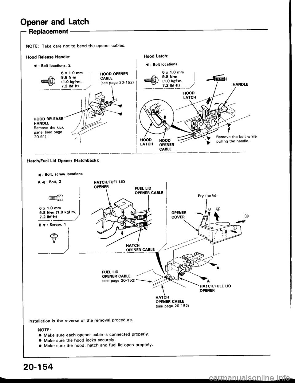
Opener and Latch
Replacement
NOTE: Take care not to bend the opener cables.
Hood Relsase Handle:
< i Bolt locations, 2
Hood Latch:
< : Bolt locations
6 x 1.0 mm9.8Nm(1.0 kgl m,7.2 tbl.lrl
HOOD OPENERCABLE(see page 20'152)
6 x 'l.O mm9.8Nm11.0 kgl m,7 .2 tbt ftl,/HANDLE
HOODLATCH
HOOD RELEASEHANOLERemove the kickpanel (see page
20-91).HOODLATCHHOODOPENERCABLE
Remove the bolt whilepulling the handle.
I
Hatch/Fuel Lid Opener lHatchback):
< : Bolt, sclow locations
A
6' I
vl
/
HATCHiFUEL LID
OPENER
6 x 1.0 mm
9.8 N m 11.0 kgl'm,
7.2 tbl.fr)
FUEL LIDOPENER CAELE
lnstallation is the reverse of the removal procedure'
NOTE:
a Make sure each opener cable is connected properly
a Make sure the hood locks securely
a Make sure the hood, hatch and fuel lid open properly.
the
J'o
t
OPENERCOVER
HATCHOPENER CABLE(see page 20-152)
@
t-
20-154
Page 1024 of 1413
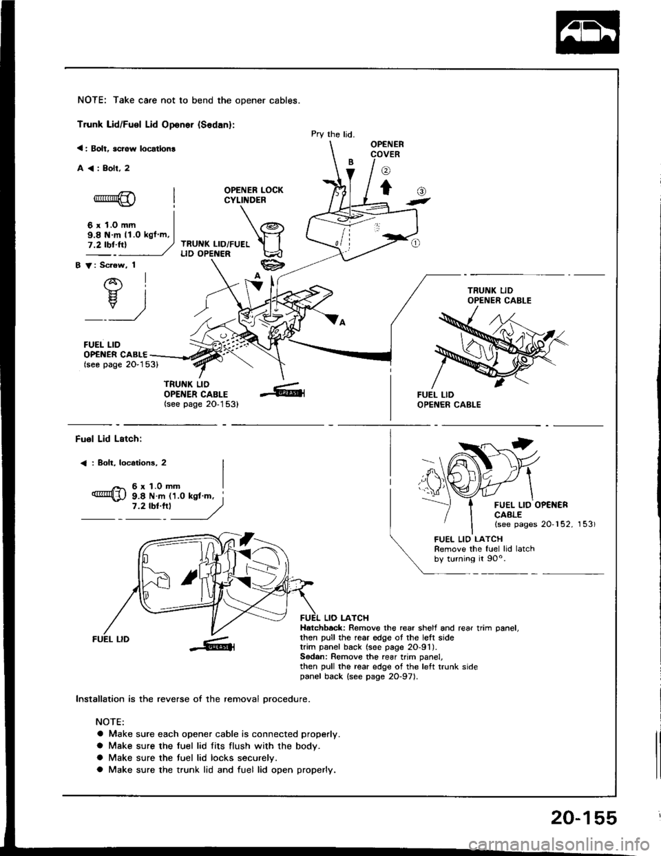
NOTE: Take care not to bend the opener cables.
Trunk Lid/Fuel Lid Oponer {Sodan}:
< : Bolt, scrow locatlon!
A<:Bolr,2
OPENER LOCKCYLINDER
TRUNK LID/FUELLID OPENER
B V: Scrow, 1
AI-}{- IH. I
_:_)
FUEL LID
Pry the ljd.OPENERCOVER
o
to-*rr*@
6 r 1.0 mm
()t
OP€NER CABLE(seo page 2O-153)
TRUNK LIDOPENER CABLE(see page 20-1 53)
9.8 N m 11.O kgl m,
Fuol Lid Lstch:
< : Boh, locotions, 2
6r1.0mm
FUEL LID OP€NERCAALE(see pages 20-152, 153)
9.8 N m 11.0 ksl'm, i7 '2 tbt'''l
------,//
FUEL LID
lnstallation is the reverse of the removal orocedure.
NOTE:
a Make sure each opener cable is connected properly.
a Make sure the fuel lid fits flush with the body.
a Make sure the tuel lid locks securelv.
a Make sure the trunk lid and fuel lid open properly.
LIO LATCHHatchbock: Remove the rear shelf and rear trim oanel.then pull the rear edge ot the lett sidetrim panel back (soe page 2O-91).Sodan: Remove the rear trim panel,then pull the rear edge of the left trunk sidepanel back {see page 2O-971.
FUEL LIO LATCHRemove the fuel lid latchby turning it 90o.
20-155
Page 1059 of 1413
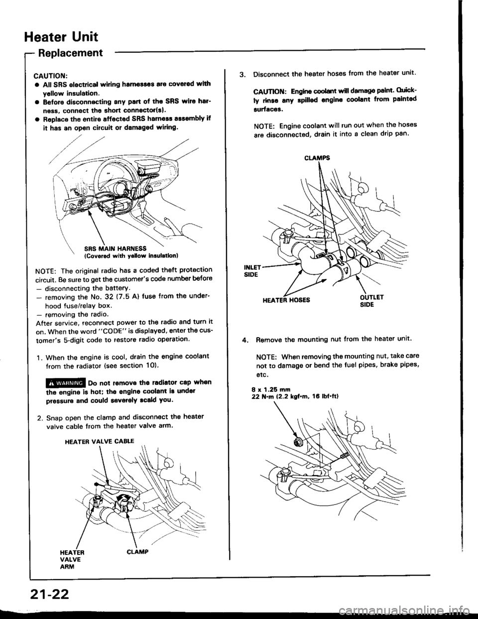
Heater Unit
Replacement
CAUTION:
a All SRS electrical witing hame$os are covoed wlth
yollow insulation.
a Before disconnecting any patt of tho SRS wito har-
neas, connect tha shott connoctol(s|.
a Roplaco th€ enlire sffacted SRS harnosr a$smbly if
it has an opon cilcult or dsmaged wiring.
NOTE: The original radio h8s a coded theft protection
circuit. Be sure to get the customer's code number betors
- disconnecting the bafterY.
- removing the No. 32 (7.5 A) fuse from th€ under-
hood tuse/relav box.- removing the radio
After service. teconnect power to the radio and turn it
on, when the word "CODE" is displayed, enter the cus-
tomer's 5-digit code to restore radio operation.
1. When the engine is cool, dtain the engine coolant
from the radiator (see section 1O).
@@ oo not lomove tho radiator cap whan
the ongine is hol; tha ongino coolant is undot
pressure and could a€voralY tcald you.
2. Snap open the clamp and disconnect the heater
valve cable from the heater valve arm.
HEATER VALVE CABLE
21-22
CLAMFS
3. Disconnect the heater hoses from the heater unit'
CAUTIOII: Engino coobnt will damago paint. orick-
ly dnse any rpilled engine coolant from paintod
surfac63.
NOTE: Engine coolant will tun out when the hoses
are disconnected, drain it into a clean drip pan'
HEATER HOSES
Remove the mounting nut from the heater unit.
NOTE: When removing the mounting nut, take care
not to damage or bend the fuel pipes, brake pipes,
etc.
8 r 1,25 rn|n22 N.m 12.2 kgt.m, tO lbf'ftl
4.
Page 1107 of 1413

Electrical
Special Tools
Troubleshooting
Tips and Precautions ................................ 23-3Five-stop Tloubleshooting ..............,...-..-... Z3-sSchematic Symbols ................................_. 23-6wire Color Cod€s ..................................... 23-6Relay and Control Unit Locations
Engine Compartment .........,............ ... --. 23-7Dsshboard and Door ..,,......................... 23-gDashboard and Floor ............................. 23-t OOuaner Panel .....-.....23-12Connector ldentification and WireHarness Routing ........ 23-i 3
Index to Circuits and Systems
Airbag ............... ...-..-... 2g-26sAir Conditioning ....,.. Section 2lAltelnator ......_.............. 23-99Anti-lock Brake Systsm (ABS) Section 19Automatic Transmission Section 14Battery .............. .......... 23-66Chafging System ........... 23-98rCigalstte Lighter .....................-...-......-..-.. Z3-2O4Cfock ................. ..........23-197rcruise Controf .......--..-... 23-242Distributor .................... 23-87Fan Controls ................. 23-1ogFuel and Emissions ... Section 1i*Fuses
Under-dash Fuse/Relay Box ................... 23-48Undor-hood ABS Fuse/Retay Box ............ 23-51Under-hood Fuse/Relay Box,.................. 23-52rGauges
Engine Coolant Temperature {ECT)Gauge ................ ..23-126Fuef cauge ............... 2g-123'Gauge Assembly ....--.23-113Speedometer .....-...,,. 23-114Tachometer .....,.....-.. 23-114Ground Distribution ........ 23-60Heater ,,,........,.... ..... Section 2lrHorn ................. ........... 23-199*fgnition Switch ............. 23-70fgnition Syst6m .......-..-.. 23-A7lgnition Timing .............. 23-89Indicator Lights"A/T Gear Position .............. ................... 23-1 32B1ak6 System ...,..,..-.23-127Engine Oil Pressura .............................. _ 23-1 51Low Fuel ............ ......23-125Malfunction Indicator Lamp {MlL} ...,,. Section I l
tfnteglated Control Unit ...29-144*lnterlock System ...................................... 23-1 3gLights, Exteriol
Back-up Lights ........... 23-179Brake Lights .............. 23-t8ltDaytime Running Lights {Csnada} ........... 23-156Front Palking Lights ............................. 23-1 65Flont Side Marker Lights ....................... 23-165Front Turn Signal Lights ........................ 23-1 65*Hazard Warning Lights .........................- 2g-1A4Headlights ................. 23-t6tLicense Plate Lights .............................. 23-1 69Taillights(Harchback) .......... 23-166
{Sedan) .............. .. 23-167Lights. Inteliol
Cargo Area Light {Hatchback) ...... -.. -.. -... 23-177Ceifing Light ........-..-.23-175
Dash Lights Blightness Controt .............. 23-t70Glove Box Lighr ................................... 23-1 69Spotfighr ............ ....-.23-174Trunk Light (Sedanl ............... .............. - 23.-177*Lighting Sysrem .......-.-... 23-152:Moonroof ,,.,.......,..,,,,,.-.23-211PGM-FI Systom ........ S€crion 11Power Distribution .,.-..--..23-54Power Door Locks .............,,..................... 23-233Power Mirors ..,..,....-...- 23-216Power Relays ...........,..... 23-68Power Windows ............ 29-222*Rear Window Defogger ........,... ..........,..... - 23-20,6Reminder Systems
Key-in Remindel System ....,.............,.... 23-1 50Lights-on Reminder System ................... 23-l 5f*Maintenance Reminder system ..,,.... -.. - -. 23-.1 2gSeat Belt Reminder System ..................- 23-125*Side Markel/Turn Signal/Hazard
Ffasher System .,..,..-.23.-1A4Spark Pfugs .........-...-..... 23-97Starting System ....,,.....-. 23-73*Stereo Sound System ...,.......................,,.. 23-l gg
Supplemental Restraint System {SRS} ......... 23-265Vehicfe Speed Sensor {VSS) .............--..-.... 23-122*Wiper/Washer Systom ...............--.........-..- Zg-254
rRead SRS pi€cautions on Page 23-271 betore workingin these areas.
-+
Page 1108 of 1413
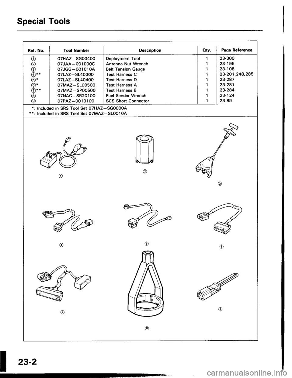
Special Tools
Rel. No. I Tool NumbolDescriptionOty. I Pago R6toronce
o
o
@
@.'
@'
@'
o--
@
@
07HAZ-SG00400
07JAA-001000c
07JGG-001010A
07LAZ-S140300
oTLAZ-S140400
oTMAZ-S100500
oTMAZ-SP00500
oTNAC-SR20100
oTPAZ-0010100
Deployment Tool
Antenna Nut Wrench
Belt Tension Gauge
Test Harness C
Test Harness D
Test Harness A
Test Harness B
Fuel Sender wrench
SCS Short Connecto.
23-300
23-195
23-108
23-201 ,248,285
23-247
23-241
23-244
23-124
23-89
lncluded in SRS Tool Set oTHAz-SGoOooA
Included in SRS Tool Set OTMAZ-SLOo10A
o
@@
o
@
I
z3-2