Page 1291 of 1413
UNDEN-HOOD FUSE/RELAY 8OX
N0.41 1100A) No.40 (50A)
Gircuit Diagram
COMBINATIONLIGHTSWTCHA.---of-RED/GRN
IGNITION SWITCH
/6i\WHT/BTK +WHT+ +- BIK/YET
\jv
UNDER-DASH FUSE/RELAY 8OX
FUSE HOTJER
GRN/BtU
TURN SIGiIALswtTcH
I
|l
+DASH TIGHTSBRIGHTNESSCONTROLLER
SIOE MAFKER LIGHTFLASHER CIRCUITlln tho intogruted controlunitl
RIGHT TURN SIGNAT TIGHTS
INOICATOR I FRONT I REARL|GHT I t32CD I t32CPl(1.4W1
23-185
Page 1292 of 1413
Side Marker/Turn Signal/Hazard Flasher System
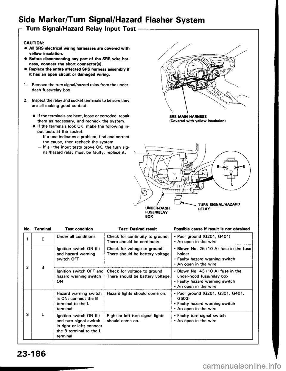
Turn Signal/Hazard Relay Input Test
CAUTION:
a All SRS electrical wiring harn6ss6s ar€ covered with
yellow insulation.
a B€foro disconn6cting any part of th€ SRS wire har-
noss, connoct tho short connector(s).
a Replaco tho ontiro sftoctod SRS harness ass€mbly it
it has an open circuit or damagod wiring,
I . Remove the turn signal/hazard relay from ths under-
dash Juse/relay box.
2. Inspect the relay and socket terminals to be sure they
are all making good contact.
a It the terminals are bent, loose or coroded, repair
them as necessary, and recheck the system.
a lf the terminals look OK, make the tollowing in-
put tests at the socket.- lf a test indicates a problem, find and correct
the cause, then recheck the system.- lf all the input tests prove OK, the turn sig-
nal/hazard relay must be taulty; replace it.
UI{DEB-DASHFUSE/RELAYBOX
Test: D€sired rosult
SBS MAIN HAR ESS{Covg.ed with yollow inrulltion)
TelminalTeEt conditionPo$iblo causo it fosult is not obtainod
,lEUnder all conditionsCheck for continuity to ground:
There should be continuitv.
. Poor ground (G201 , G4O1). An oDen in the wire
2B
lgnition switch ON (ll)
and hazard warning
switch OFF
Check for voltage to ground:
There should be battery voltage.
Blown No. 26 (10 A) fuse in ths fuse
holder
Faulty hazard warning switch
An open in the wire
lgnition switch OFF and
hazard warning switch
ON
Check for voltage to ground:
There should be battery voltage.
Blown No. 43 (10 Al fuse in the
under-hood fuse/relay box
Faulty hazard warning switch
An ooen in the wire
3
Hazard wa.ning switch
is ON; connect the B
terminal to the L
termrnat.
Hazard lights should come on.Poor ground (G2O1, G3O1, G4O1
G503)
Faulty hazard warning switch
An open in the wire
lgnition switch ON (lll
and turn signal switch
in right or left; connect
the B terminal to the L
terminal.
Right or left turn signal lights
should come on.
. Faulty turn signal switch. An open in the wire
23-186
-
Page 1294 of 1413
Stereo Sound System
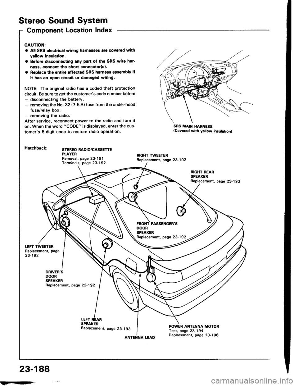
Component Location Index
LEFT TWEETERReplacement, page
23-192
DRIVER'SDOORSPEAKERRepfacement, page 23-192
CAUTION:
a All SRS el€ctrical wlring harneaseE are covered with
yallow insulation.
a Belore dbconnscting any part of the SRS wire har-
nass, connect tho short connector(sl.
a Replace tho entir6 affoctod SRS harn6ss assembly if
it has an opan circuit or damag6d widng.
NOTE: The original radio has a coded theft protection
circuit. Be sure to get the customet's code number belore- disconnecting the battery.- removing th€ No. 32 (7.5 A)tuse from the under-hood
fuse/relay box.- removing the radio.
After service, reconn€ct power to th€ radio and tutn it
on. When the word "CODE" is displaved, enter the cus-
tomer's 5-digit code to restore radio opelation.
Hatchback:STEBEO RADIO/CASSETTEPTAYERRemoval. paoe 23-191Terminals, page 23-192
SBS MAII{ I{ARI{ESS(Covor€d wirh y6llow in3ulationl
LEFTSPEAKER
RIGHT REARSPEAKERReplacement. page 23-193
ANTENNA MOTORTest, page 23-194
DOORSPEAKERRepfacement, page 23-192
23-188
!iltil;s'
Replacemenr. page 23-193
Replacement, page 23-196
Page 1297 of 1413
Unit Removal
CAUTION:
a All SRS oloctrical wi ng harn.$.s ara covcrrd withyellow insulation.
a B€toro disconnocting any part ot tho SRS wirc hrr-
nosa, connsct tho short conn6ctol(rl.
a Raplaco the sntirs sttoctod SRS hamoas asacmbly it
it has an opon circuil 01 damagod widng.
NOTE: The original radio has a coded theft protection
circuit. Be sure to get the customer's code number b€lore- disconnecting the battery.- removing the No. 32 (7.5 A) fuse in the under-hood
fuse/relay box.- removing the radio.
After ssrvice, reconnect power to the radio and turn it on.
When the word "CODE" is displayed, enter the cus-
tomer's 5-digit code to restore radio operation.
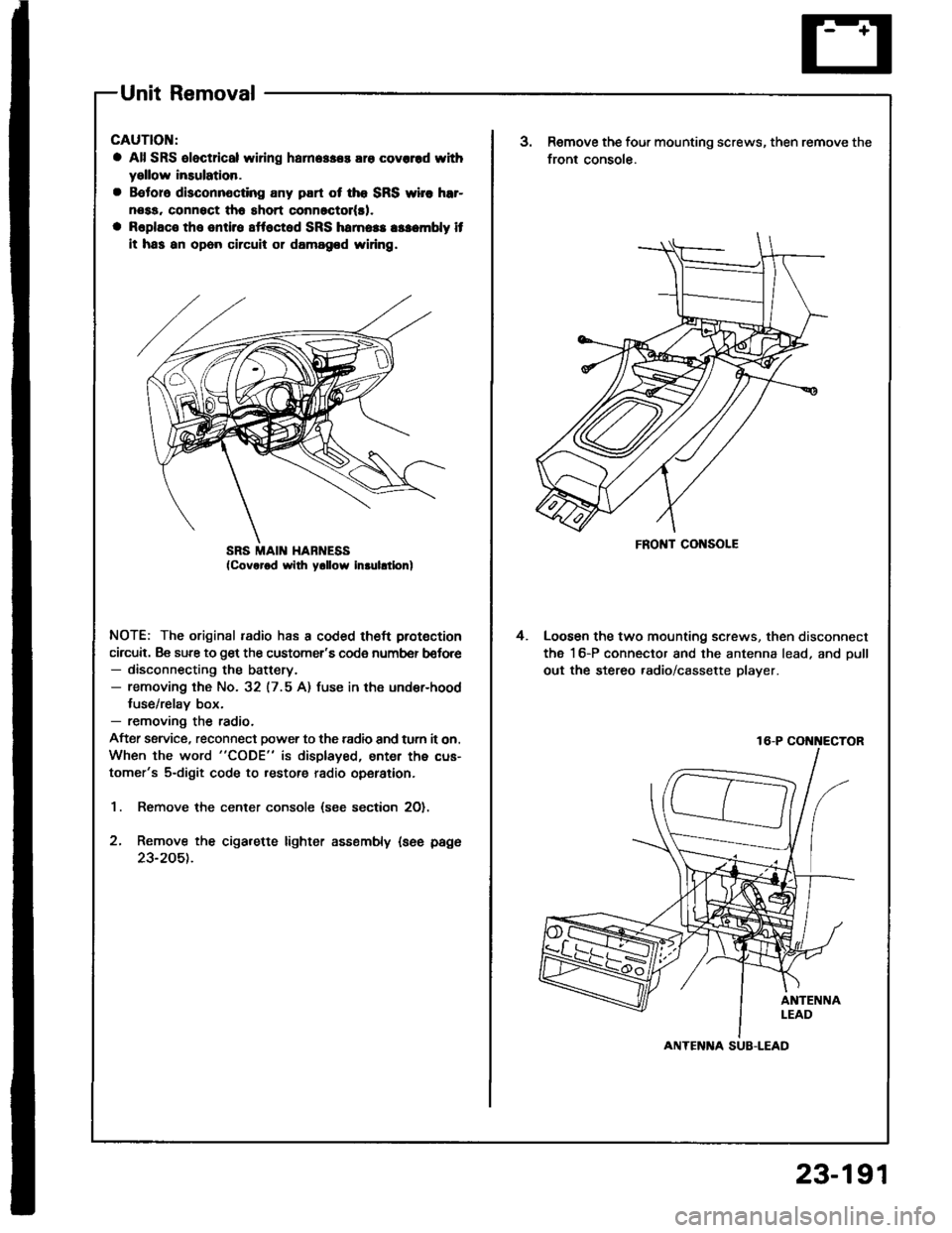
1. Remove the center console (see section 2O).
2, Remove the cigarette lighter assembly {see page
23-205t.
SRS MAII{ HABNESSFRONT CONSOLE
3.Remove the four mounting screws, then remove the
front console.
Loosen the two mounting screws, then disconnect
the 16-P connector and the antenna lead, and oull
out the stereo .adio/cassette player.
4.
16-P COi{i{ECTOR
ANTENlTA SUB-LEAD
23-191
Page 1307 of 1413
Switch Test
CAUTION:
a All SRS el6ctrical wiring harnossos are covarod withyellow inaulation.
a Beforo disconnecting any pan ot the SRS wire har-neaa, connoct ths short connector(s).a Roplace the entil€ afloctod SRS harne$ a$6mbly ifit has an open circuit or dsmagad wlring.
NOTE; The original radio has a coded theft protection
circuit. Be sure to get the customer's code number before- disconnecting the battery.- removing the No. 32 {7.5 A) fuse lrom the under-hoodtuse/relav box.- removing the radio.
After service, reconnect power to the radio and turn iton. When the word "CODE" is displayed, enter the cus-tomer's 5-digit code to restore radio operation.
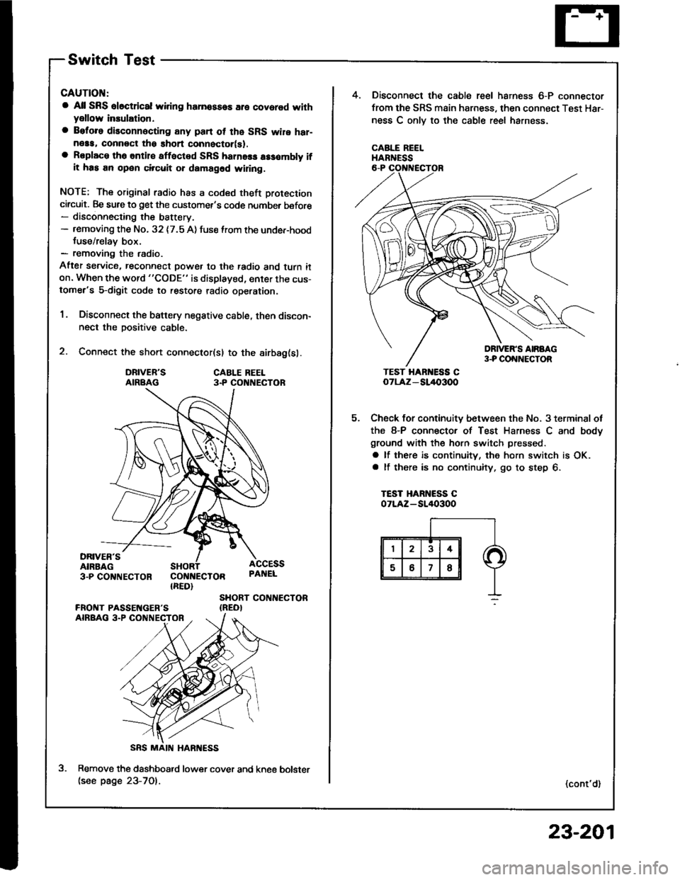
1. Disconnect the battery negative cable, then discon-nect the positive cable.
2. Connect the short connector(sl to the airbag(sl.
DRIVER'SAIRBAGCABLE REEL3.P CO NECTOR
DRIVER'SAIRBAG3-PCO'TNECTOR COI{NECTOR{RED}
ACCESSPAI{EL
SHORT CONTIECTOR{REO}
Remove the dashboatd lower cover and kne€(see page 23-701.
5.
4. Disconnect the cable reel harness 6-P connector
from the SRS main harness, then connect Test Har-
ness C onlv to the cable reel harness.
CABLE REELHARNESS
TEST HAR ESS CoTLAz - SL/l{,3OO
Check for continuity between the No, 3 terminal ot
the 8-P connector of Test Harness C and body
ground with the horn switch pressed.
a lf there is continuity, the horn switch is OK.a lf there is no continuity, go to step 6.
TEST HARNESS COTLAZ-SI/I()3OO
(cont'd)
bolster
23-201
Page 1330 of 1413
Power Windows
Circuit Diagram (Hatchback)
UNDER - HOOD FUS€/REI.AY BOX
tlo.41 l100Al ilo.39 {50A)
UNOER- OASH FUSE]NEI.AY 8OX
8LX z
G50tG502
D PASSENGER'SwrNDowswITcH
PASSENGEN'SwtN00w M0T0nG401
23-224
Page 1350 of 1413
+ No.24 ll5Al: 81881 onoineNo.24 l20Al: 818C1 ensine
UNDER-DASH FUSE/RELAY BOX
HORN
Y
UNOER _HOOD FUSE/RELAY BOX
No.4l (100A) No.39l50A)
INDICATORTIGHT{0,91W}
IP
I D Suur
6yffi Bi,G#,,'.
BTK
t-
G201G401
II
I
f7
VEHICLE SPEEDSENSOR iVSS)
M/r : CLUTCH SWITCH IA/T : A/T GEAR IPOS|T|oN SWTTCH IInIEI,E) I
PNK
BI-K
T
G201G401
Cruise Gontrol
Circuit Diagram
23-244
Page 1351 of 1413
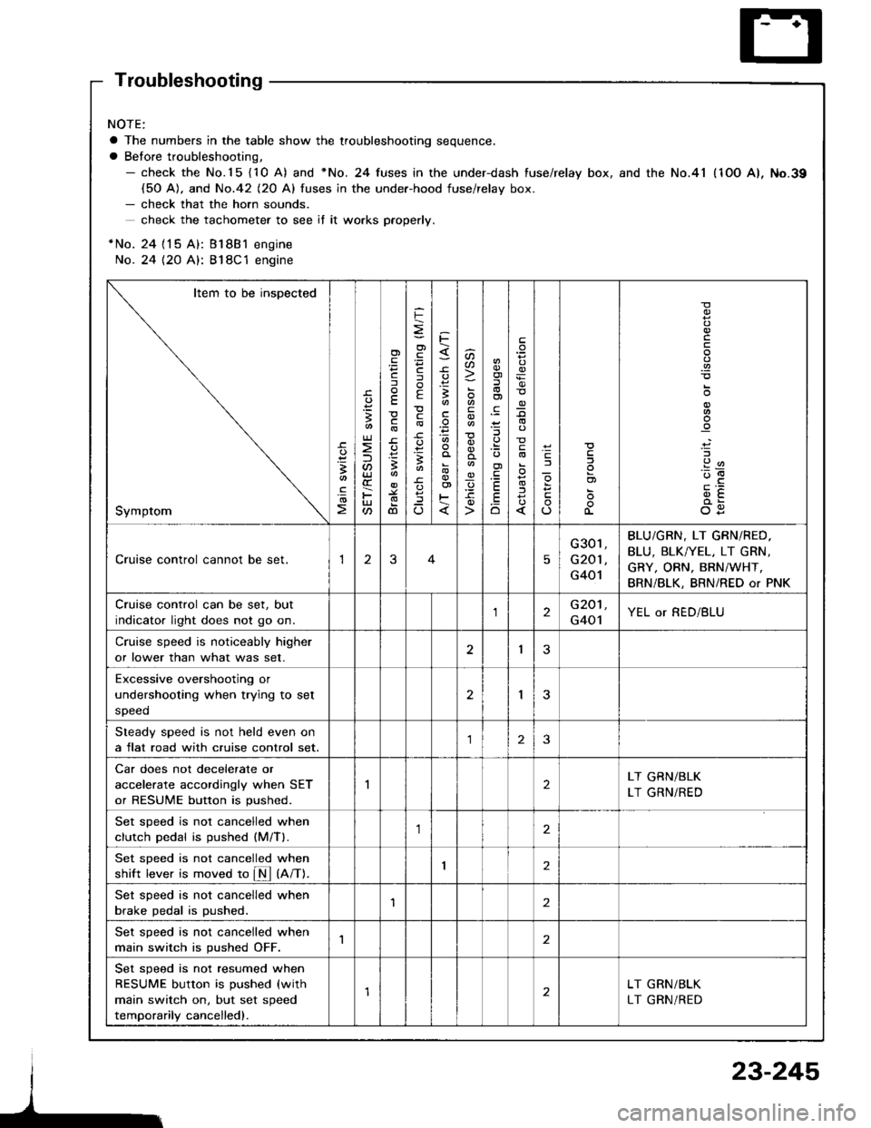
Troubleshooting
NOTE:
a The numbers in the table show the troubleshooting sequence.
a Before troubleshooting,- check the No.15 {10 A) and *No. 24 fuses in the under-dash fuse/relay box, and the No.41 (1OO A), No.39(50 A). and No.42 (20 Al fuses in the under-hood fuse/relav box.- check that the horn sounds.
check the tachometer to see if it wo.ks pfoperly.
*No. 24 {15 A): Bl8B1 engine
No. 24 {2O A}: 818C1 engine
Item to be inspected
Symptom
-c.
!I
.!o
;
U)
F
'Fcf
E
c
3
dl
F
o)
F
f
E
c
B
^
3
'.E
aa
_q
E
oi
.9:
E
.Eo
_9
l
If
L
!
.9
912'oE
og
Cruise control cannot be set.13
G301,
G201 ,
G401
BLU/GBN, LT GRN/RED.
BLU, BLK/YEL, LT GRN,
GRY, ORN. BRN/WHT,
BRN/BLK, BRN/RED or PNK
Cruise control can be set, but
indicator light does not go on.2G201,
G401YEL or RED/BLU
Cruise speed is noticeably higher
or lower than what was set.I3
Excessive overshootjng or
undershooting when trying to set
speed
2I
Steady speed is not held even on
a flat road with cruise control set.23
Car does not decelerate or
accelerate accordingly when SET
or RESUME button is pushed.
2LT GRN/BLK
LT GRN/RED
Set sDeed is not cancelled when
clutch Dedal is oushed (M/Tl.,1
Set sDeed is not cancelled when
shift lever is moved to fM tnnt.I2
Set speed is not cancelled when
brake pedal is pushed.'I2
Set speed is not cancelled when
main switch is pushed OFF.1
Set speed is not resumed when
RESUME button is pushed (with
main switch on, but set speed
temporarily cancelled).
LT GRN/BLK
LT GRN/RED
23-245