Page 1229 of 1413

Fuel Gauge
Gauge Test
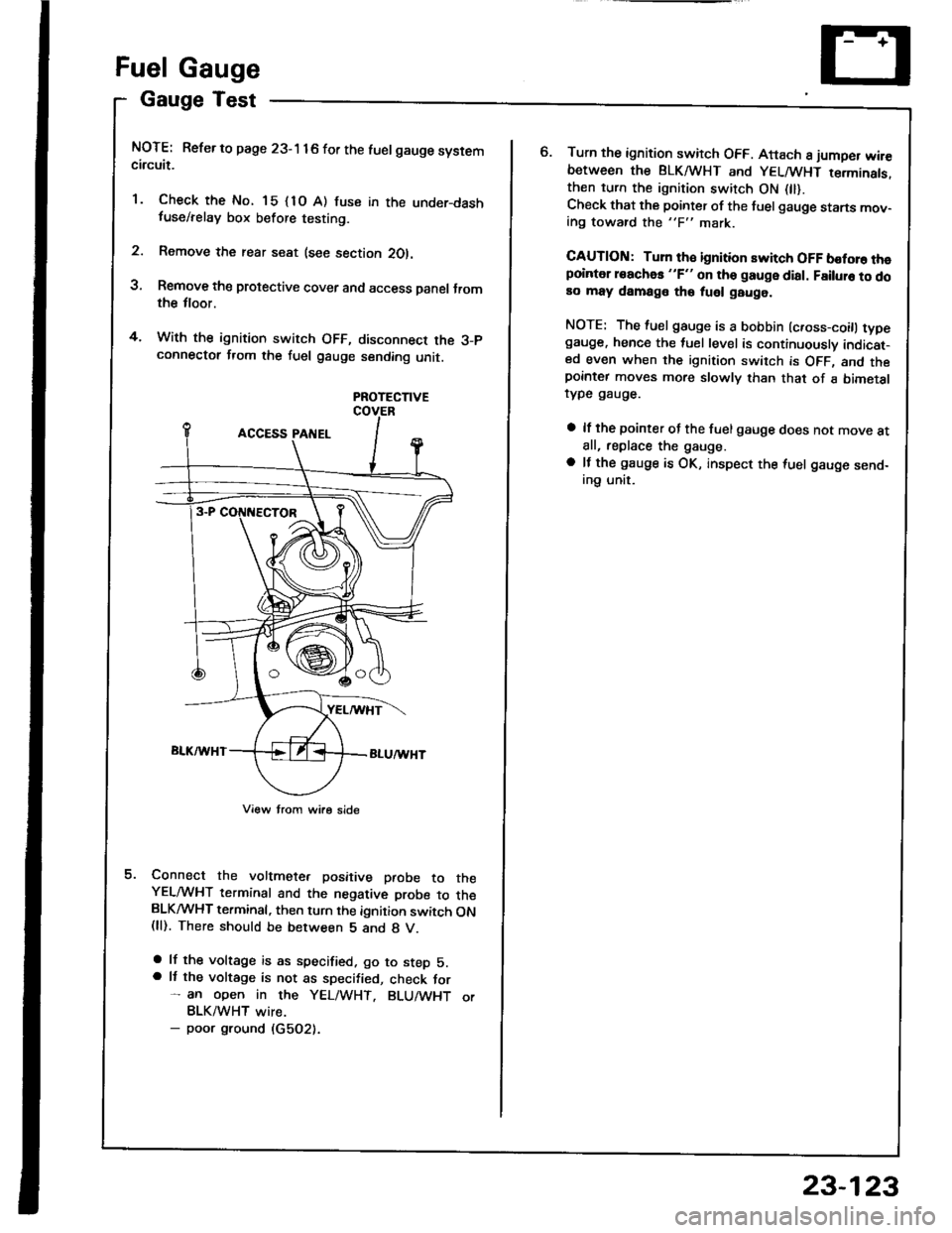
NOTE: Refer to page 23-1 16 for the luelgauge systemcircuit.
'1. Check the No. 15 {1O A) fuse in the under-dashfuse/relay box before testing.
2. Remove the rear seat (see section 2Ol.
3, Remove the protective cover and access Danel Jromthe tloor.
4. With the ignition switch OFF, disconnect the 3-pconnectot from the fuel gauge sending unit.
PROTECTIVE
Connect the voltmete. positive paobe to theYELMHT terminal and the negative probe to theBLKMHT terminal, then turn the ignition switch ON(ll). There should be between 5 and 8 V.
a lf the voltage is as specified. go to step 5.a It the voltage is not as specified, check for- an open in the YEL/WHT. BLU/WHT orBLK/WHT wire.- poor ground (G5O2).
o.Turn the ignition switch OFF. Attach 8 jumper wir€between the BLKA HT and YELMHT terminats.then turn the ignition switch ON 0l).Check that the pointer of the fuel gauge starts mov-ing toward the "F" mark.
CAUTION: Turn th€ ignition switch OFF boforo thepointer roachas "F" on tho gauge dial. Failuro to doao may damage tho fuel gauge.
NOTE: The fuel gauge is a bobbin (c.oss-coitl typegauge. hence the tuel level is continuously indicat-ed even when the ignition switch is OFF, and thepornter moves more slowly than that of a bimetalrype gauge.
a lf the pointer of the fuel gauge does not move atall, replace the gauge.
a lf the gauge is OK, inspect the {uel gauge send-ing unit.
23-123
Page 1230 of 1413
Fuel Gauge
Sending Unit Test/Replacement
@ oo not lmoke while working on tho fuol
system. Kaop open flamos away from your wotk aroa.
1. Remove the rear seat (see section 2O).
2. Remove the protective cover and access panel lrom
the floor.
3. With the ignition switch OFF, disconnect the 3-P
connector from the fuel gauge sending unit.
4. Remove the tuel gauge s€nding unit.
5. Measure the resistance between the A and B termi-
nals at E (empty), 1/2 (half full) and F (full) by mov-
ing the tloat.
6. Check the change in resistance by moving the float
uo and down.
(
lf unable to obtain the above readings or it resistance
do€s not change, replace the fuelgauge sending unit.
Float PositionE
Resistance lO)105-11025.5-39.52-5
o
23-124
Page 1250 of 1413
Integrated Control Unit
Circuit Diagram
D.3c ptlon
An integrat€d control unit, located in the left kick panel, integratss the functions of tho keyin/seat beh r6mind€r, sido
markar light {lasher, wiper/washer, lights-on r6minder, rear window dsfogger timer, brak€ system light bulb check, and
enging oil pressure indicator flasher circuitE,
NOTE: Difforent wires with the same color have be6n given a numbor suffix to distinguish them (for Example,
GRN/RED1 and GRN/RED'� are not the same).
WNOSHIELD WIPER/WASHER SWITCH
IMT OFFiINT
I
II
IIIIIIIIIIII
YEUEE
rl
t
P
UNOER - DASH FUS€/RETAY BOX
r NTEGRATED COI{TROI UNIT
t-0wErGrilE 0|lPRESSI'REINDICATORLIGI{T
WINDSHIELOWIPERAVASHERswtTcH
tr-/
IBLK/GRN BI
WINDSHIELOWIPERMOTOR{Asl
VOLTAGEREGULATOR{ln ahamator,
UNOER- HOOD FUSE/RELAY 8OX
I
r3
r8relit;rBt5I
23-144
lr ) : With combinod washef-wip€r oporation
Page 1268 of 1413

Headlight
Adjustment
Belol€ adiusting lha hoadlights:
a Park the car on level ground.
a Make sure the luel tank is full.
a The driver or someone who weighs the same should
sit in the driver's seat.
a Load the trunk with the items you usually carry (if you
usually pull a trailer, attach it to the carl.
a Push down on the tront and rear bumDers several
times to make sure the car is sitting normally.
a When installing a new headlight assembly, tighten the
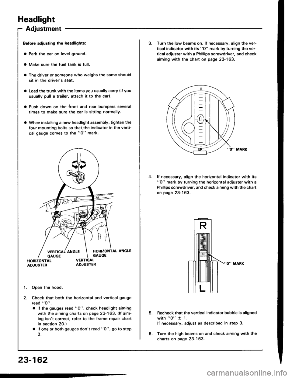
four mounting bolts so that.the indicator in the verti-
cal gauge comes to the "O" mark.
1. Open the hood.
2. Check that both the horizontal and vertical gauge
read " O" .
. lf the gauges rcad "O", check headlight aiming
with the aiming charts on page 23-163. (lf aim-
ing isn't correct, refer to the trame repair chart
in section 20.)
a lf one o. both gauges don't read "O". go to step
23-162
3. Turn the low beams on. lJ necessary, align the ver-
tical indicator with its "O" mark by turning the ver-
tical adiuster with a Phillips screwdriver, and check
aiming with the chart on page 23-163.
lf necessary, align the horizontal indicator with its"0" mark by turning the horizontal adjuster with a
Phillips screwdriver, and check aiming with the chart
on page 23-163.
4.
5.Recheck that the vertical indicator bubble is aligned
with "o" 1 1.
lf necsssary, adjust as described in step 3.
Turn the high beams on and check aiming with the
charts on page 23-163.