Page 1134 of 1413
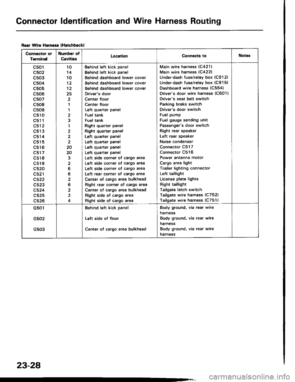
Connector ldentification and Wire Harness Routing
Roar wiro Harn$s (Hatchbsckl
Connector or
Torminal
Numbor of
CavitiosLocationConnecta tollotos
c501
c502
c503
c504
c505
c506
c507
c508
c509
LStt
c51 1
c512
c513
c514
c515
c516
c517
c5r 8
c519
c520
c521
c522
c523
c524
c525
c526
10'14
10
12
25
2
1
1
2
I
2
20
20
2
6
b
2
2
2
4
Behind left kick panel
Behind left kick panel
Behind dashboard lower cover
Behind dashboard lower cover
Behind dashboard lower cover
Driver's door
Center tloor
Center lloor
Left qusrter panel
Fuel tank
Fuel tsnk
Right quarter panel
Right quarter panel
Left quarter panel
Left quarter panel
Left quarter panel
Left quarter panel
Left side corner of cargo area
L€ft side corner of cargo area
Left side corner of cargo area
Left rear corner of cargo area
Center ot cargo area bulkhead
Right rear cornor oJ cargo area
Center of cargo area bulkhsad
Right side of cargo area
Right side of cargo area
Main wire harness (C4211
Main wire harness (C422)
Under-dash fuse/relay box (C912)
Under-dash fuse/relay box (C91 5)
Dashboard wire harness (C554)
Driver's door wire harness {C6011
Driver's seat belt switch
Palking brake switch
Driver's door switch
Fuel pump
Fuel gauge sending unit
Passenger's door switch
Right rear speaket
Left rear speaker
Noise condenser
Connector C517
Connector C516
Power antenna motor
Cargo area light
Traile. lighting connector
LeJt taillight
License plate lights
Right taillight
Tailgate latch switch
Tailgate wire harness (C752)
Tailgate wire harness (C751)
G501
G502
G503
Behind left kick psnel
Left side of Jloor
Center ot cargo area bulkhead
Body ground, via rear wire
harness
Body ground, via rear wire
harness
Body ground, via rear wire
harness
23-28
Page 1178 of 1413
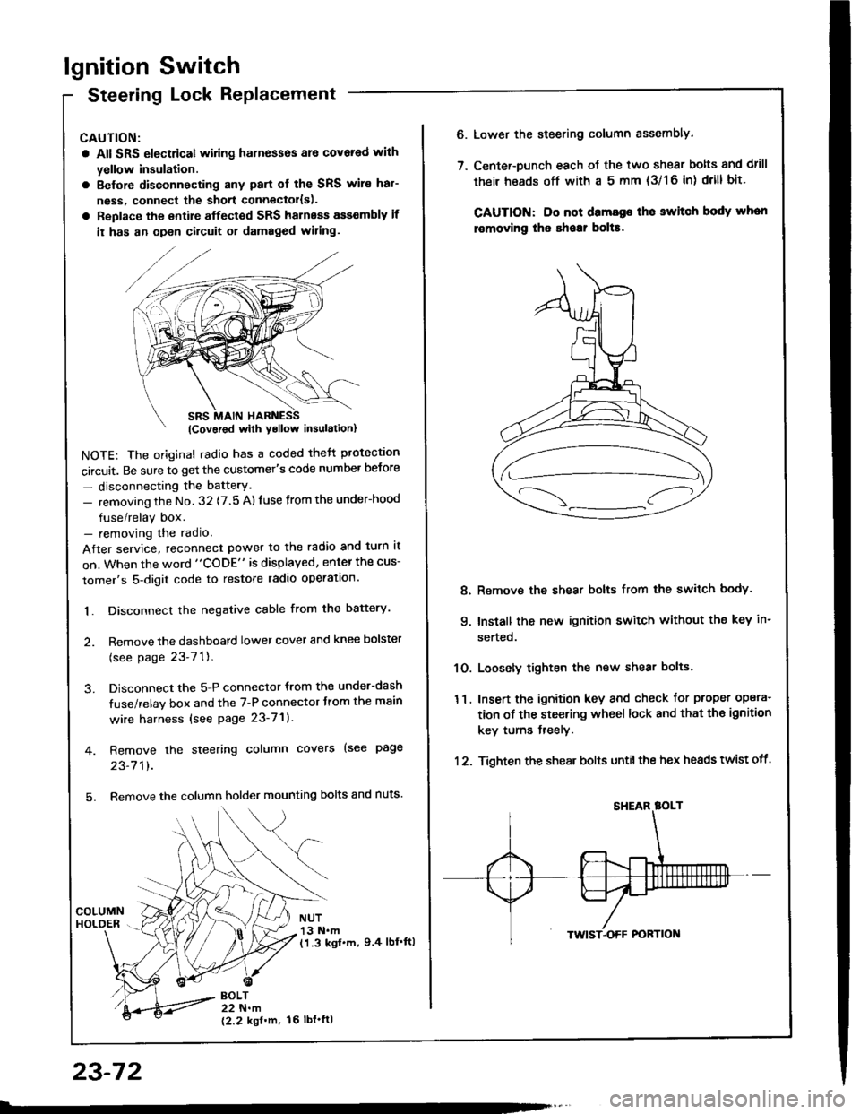
lgnition Switch
Steering Lock Replacement
CAUTION:
a All SRS electrical wiring harnesses ale covsred with
yellow insulation.
a Belore disconnecting any parl ot the SRS wir€ hal-
ness, connecl the short connector{s).
a Replace the entire alfected SRS harness a$6mbly il
it has an open circuit or damaged wiring.
NOTE: The original radio has a coded thett protection
circuit. Be sure to get the customer's code number betore
- disconnecting the batterY.
- removing the No. 32 (7.5 A) fuse from the under-hood
fuse/relay box.- removing the radio.
After service, reconnect power to the radio and turn it
on. When the word "CODE" is displayed, enter the cus-
tomer's 5-digit code to restore radio operation.
1. Disconnect the negative cable from the battery.
2. Remove the dashboald lower cover and knee bolster
(see page 23-7'l ).
3. Disconnect the 5-P connector from the under-dash
fuse/relay box and the 7-P connector trom the main
wire harness {see page 23-71).
4. Remove the steering column covers (see page
23-711.
5. Remove the column holder mounting bolts and nuts'
BOLT22 N.m
12.2 kgl'm.
NUT13 N.m(1.3 kgf.m, 9.4 lbl'ftl
23-72
16 tbt.ftl
6. Lower the steering column sssembly.
7. Center-Dunch each oJ the two shear bolts and drill
their heads off with a 5 mm {3/1 6 in) drill bit'
CAUTION: Do not dama96 tho switch body whon
r€movlng the shoar bol$.
Remove the shear bolts from the switch body.
Install the new ignition switch without the key in-
serted.
Loosely tighten the new shear bolts.
Insert the ignition key and check for proper opera-
tion of the steering wheel lock and that th€ ignition
key turns freely.
Tighten the shear bolts untilthe hex heads twist off.
8.
q
10.
11.
12.
Page 1267 of 1413
Headlight
Description
The low beam lights are proiector-type lights which are more compact while maintaining sufficient brightness. Bundling
the light rays reduces stray light and yields a spotlight-effect which improves visibility during night or foul weather driving.
For easier aiming, the headlights are equipped with vertical and horizontal gauges.
NOTE: As the oute. lenses are made oI a resin material, don't cover the headlights when they a.e turned on.
OUTER LENScoNvEx LEI{SSUB-REFLECTORsEcoND FOCUSINTERRUPTER PLATEREFLECTOBFIRST FOCUSBULB
23-161
Page 1269 of 1413
Measurements (Standardl:
A: 9 fi 10 in (3000 mm)
B: 23 in (585 mm)
C: 46.1 in (1170 mml
D: 33.5 in (85O mm)
E; 1.2 in {31 mm}
Headlight Aiming
Low beam:High besm:
HEADLIGHTLOW BEAMCEt{TER
FLOOR
HEADLIGHTHIGH BEAM
FLOOR
CAUTION: Th6 out6r lonses get very hot when tho hoadlights are on; do not cover them.
23-163
Page 1320 of 1413
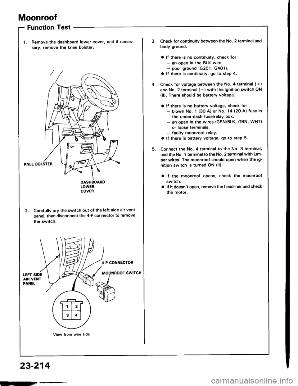
Moonroof
Function Test
Remove the dashboard lower cover,
sarv, remove the knee bolste..
and if neces-
KNEE BOLSTER
DASHBOARDLOWERCOVER
2. Carefully pry the switch out of the left side air vent
panel, then disconnect the 4-P connector to remove
the switch.
4-P CONI{ECTOR
MOOi{ROOF SWITCH
View from wire side
.r--r
ll l2lf--T� --t
l314l
23-214
Check Jor continuity between the No. 2 terminal and
body ground.
a ll there is no continuity, check for- an ooen in the BLK wire.- poor ground (G201 , G4Ol ).
a lf there is continuity, go to step 4.
Check tor voltage between the No. 4 terminal ( + )
and No. 2 terminsl { - ) with the ignition switch ON
{ll). There should be battery voltage.
a lf there is no baftery voltage, check tot- blown No. 1 (3o Al or No. 14 {20 A) fuse in
the under-dash tuse/relay box.- an open in the wires (GRN/BLK, GRN, WHT)
or loose terminals.- faulty moonroof relay.
a lf there is battery voltage, go to step 5.
Connect the No. 4 terminal to the No. 3 terminal,
and the No. 1 terminal to the No, 2 terminal with jum-
per wires. The moonroot should open when the ig-
nition switch is turned ON (ll).
lf the moonroof ooens, check the moonroof
switch,
ll it doesn't open, remove the headlinet and check
the motor.
4.
Page 1321 of 1413
Switch Test
1, Remove the dashboard lower cover.
2. Carefully pry the switch out of the left side air vent
Danel, then disconnect the 4-P connector and re-
move the switch.
3. Check lor continuity between the terminals in each
switch position sccording to the table,
MOONROOF SWITCH
Motor Test
Remove the headliner (see section 20).
Disconnect the 2-P connector from the moonroot
moror.
Check the motor by connecting power and ground
according to the table.
NOTE: Motor clutch test is in section 20.
lHatchblckl (Scd!n)
View from terminal side
It the motor fails to run or doesn't run smoothly.
replace it.
4.
Torminal
P"ri i-
---__\AID
OFFG---o
OP€No---oG-
CLOSE
o---o
Te.minal
Condition -- ---------lAB
OPENo
CLOSE@
,l
rd\./ cLos€
Y
IOPEiIIOFF
23-215
Page 1379 of 1413
Supplemental Restraint System (SRS)
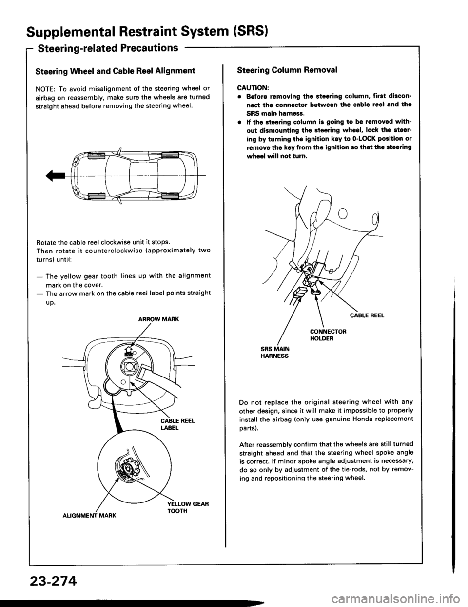
Steerin g-related Precautions
Steering Wheel and Cable Reel Alignment
NOTE: To avoid misalignment of the steering wheel or
airbag on reassembly, make sure the wheels are turned
straight ahead before removing the steering wheel.
Rotate the cable reel clockwise unit it stops.
Then rotate it co u nterclockwise (approximately two
turnsl until:
- The yellow gear tooth lines up with the alignment
mark on the cover.- The arrow mark on the cable reel label points straight
up.
ALIGNMENT MARK
ARROW MARK
23-274
Steering Column Removal
CAUTION:
. Bofore romoving tho 3l6oring column, first discon'
nect tha connector between ths cablo 16ol snd tho
SRS main harness.
. lf th6 stssring column is going to be removed with-
out dbmounting the stesring wh6el, lock the sl6sr-
ing by turning th€ ignition k.y to o-LOCK po3ition or
removo tha k€y llom ths ignilion so that th6 3loaring
wheel will not turn.
Do not replace the original steering wheei with any
other design, since it will make it impossible to properly
instsll the airbag (only use genuine Honda replacement
oans).
After reassemblv confirm that the wheels are still turned
straight ahead and that the steering wheel spoke angle
is correct, lf minor spoke angle adjustment is necessary,
do so only by adjustment of the tie-rods, not by remov-
ing and repositioning the steering wheel.
Page 1408 of 1413
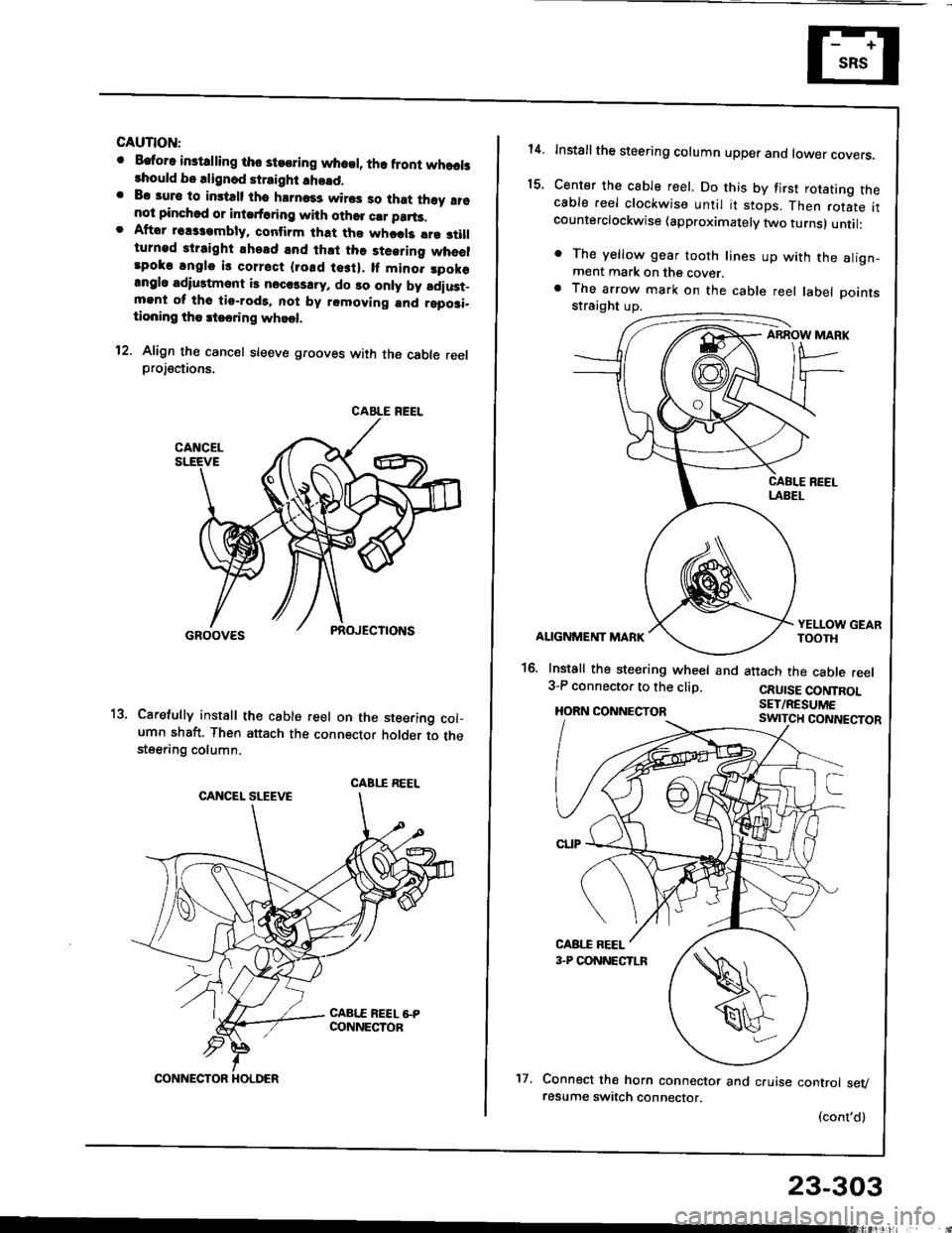
GAUTION:
o Eatora instdling tho steoring whosl, lha front whaelslhould bo alignod straight !ho!d.. Bc auro to imtalt tho hrrnass wiros so that th6y !16not pinchod or intsrt6ring with othor crr parts.. Aftor rsassambly. conlirm that tho whods lre 3tillturnad straight ahead and lh.t the steering wheolrpoko angle is corrsct {rosd tesi}. lf mino. spok€angl6 adiustmont is necols!ry, do 30 only by ldiust_mgnt ol tho tio-rod9. not by removing and rgposi-tioning tho rteering whoel.
12. Align th€ cancel sleeve grooves with the cable reelprojections.
Carefully install th€ cable reel on the steering col-umn shaft. Then attach the connector holder to thesteering column.
CABLE REEL
CABI.I REEL
CONNECTOR HOLDER't7.
23-303
14.
t5.
Installthe steering column upper ano tower covers.
Center the cable reel. Do this by first rotating thecable reel clockwise until it stops. Then rotate itcounterclockwise (approximately two turns) until:
. The yellow gear tooth lines up with the align-ment mark on the cover.a The arrow mark on the cable reel label Dointsstraight up.
ABROW MARK
ALIGNMENT MARK
16. Install the steering wheel and3-P connector to the clip.
HORN CONNECTOR
YELLOW GEARTOOTH
attach the cable reel
CRUISE CONTROLSET/RESUME
Connect the horn connector and cruise control sevresume switch connector.
(cont'd)