1994 HONDA INTEGRA Radiator
[x] Cancel search: RadiatorPage 1075 of 1413
Troubleshooting
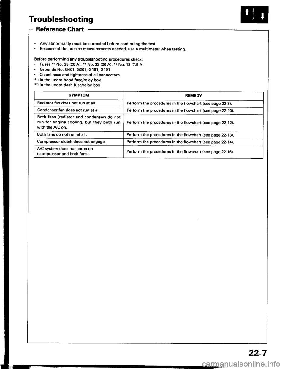
Reference Ghart
. Any abnormality must be correctsd before continuing the test.. Because of the precise measurgments needed, use a multimeter when testing.
Before performing any troubleshooting procedures check:. Fus€s .r No. 35120 A), *1 No. 33 (20 A), ), No. 13(7.5A). Grounds No. G401, G201, G'151, G101. Cleanliness and tightness of all connectors*1: In the under-hood fuse/relay box*2: In the under-dash fuse/relay box
SYMPTOMREMEDY
Radiator fan does not run 8t all.Perform the procedures in the flowchan (see page 22-8).
Condenser fan does not run at all.Perform the procedures in the flowchart (see page 22-10).
Both fans (radiator and condenser) do not
run for engine cooling, but they both run
with the Ay'C on.
Perform the procedures in the flowchan (see page 22-12).
Eoth fans do not run at all.Perform the procedures in the flowchart (see page 22-13).
Compressor clutch does not engage.Perform the procedures in the flowchart (see page 22-14).
Ay'C system does not come on
{compressor and both fans}.Perform the procedures in the flowchart (see page 22-16).
22-7
Page 1076 of 1413
Troubleshooting
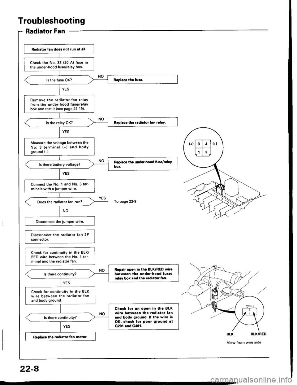
Radiator Fan
Redi.to. fan doo3 not run at all.
check rhe No. 33 {20 A) fuse inthe under-hood luse/relay box.
Remove the radiator lan r€layfrom the under-hood Iuse/relaybox and test it (see page 22-19).
Raplaca tha radiator tln rahy.
Measure the voltage between theNo. 3 terminal (+) and bodyground {-}.
ls therg battery voltag€?
Connect the No. 1 and No. 3 ter-minals with a jumper wire.
Does the radiator Ian run?
Chock for continuity in the BLK./RED wire between the No. 1 ter-minal and the radiator fan.
R.p.ir opdr in th. 8LK/RED wir.batwaon th. unda.-hood fut./ralay box rnd tha radirtor f.n.
Check for continuity in th€ BLKwire between the radiator {anand body ground.
Ch.ck to..n op.n in th. BLKwirc batwaan th. rldirtor hnlnd body ground, lf tha wita i!OK, chack tor poor gtound rtG2ol lnd GiOl.
Rephco tho radi.tor frn motor.
To p3ge 22-9
22-A
Page 1085 of 1413
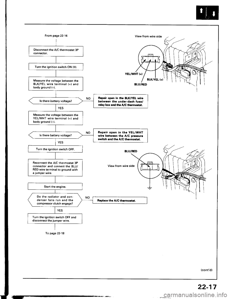
From page 22-15
Turn the ignition switch ON (IIl.
Measure tho voltage betweon theBLK/YEL wire terminal (+) andbody ground (-).
R.p.i. op.n ir th. BLX/YEL wirobatwc.n tha unda.-darh fuao/r.l.y box .rd rh. A/C th.rmo.t!r.
Measure th€ voltage between theYEL/WHT wire terminal {+} andbody ground (-).
R.prir op.n in th. YEL/WHTwiro bctwaan tha A/C praaau.crwhch .nd th. A/C th..mo.ht.
ls there battory voltage?
T!rn the ignition switch OFF.
R€connect the Ay'C thermostat 3Pconn€ctor and connect the BLU/RED wire terminal to ground witha l!mper wire,
Do the radiator and con-donser fans run and thecompressor clutch engage?
Turn the ignition switch OFF anddisconn6ct the jumper wire.
YEL/WHT l+l
View from wir€ side
To page 22-18
(cont'd)
22-17
Page 1087 of 1413
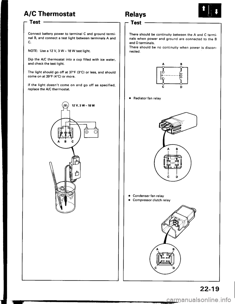
A/C Thermostat
Test
Connect battery power to terminal C and ground termi-
nal B, and connect a test light between terminals A and
NOTE: Use a 12 V, 3W- 18Wtest light.
Dip the A-/C thermostat into a cup filled with ice water,
and check the test light.
The light should go off at 37"F (3"C) or less. and should
come on at 39"F (4"C1 or more.
lf the light doesn't come on and go off as specified,
replace the Ay'C thermostat.
There should be continuity between the A and C term!nals when power and ground are connected to the Band D terminals.
There should be no continuity when power is discon-nected.
. Radiator fan relay
Condenser fan relay
Compressor clutch relay
Relays
a
a
,I Ir-b
InP.I I
12V.3W-18W
ABC
22-19
Page 1091 of 1413
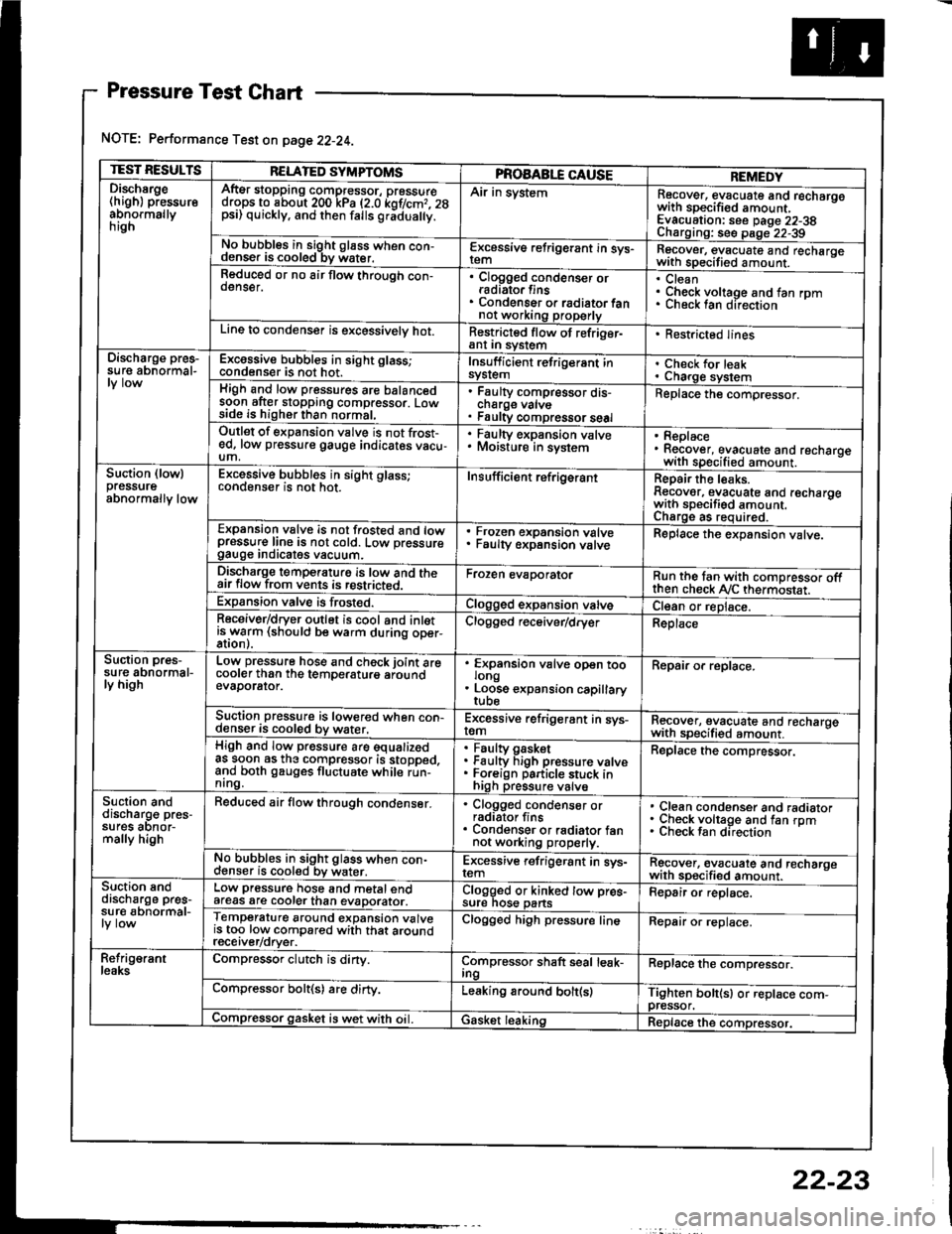
Pressure Test Chart
NOTE: Performance Test on page 22-24.
TEST RESULTSRELATED SYMPTOMSPROAABLE CAUSEREMEDYDischsrge(high) pressureabnormallynrgn
AftEr stopping compressor, pressuredrops to about 200 kPa (2.0 kof/cmr. 28psi) quickly, and then falls gr;dua y.
Air in systemRecover, evacuate and recharqowith sDecified amount. -
Evacuation: see Daqe 22-38Charoino: se6 D;op--2?-?qNo bubbles in sight g16ss when con-denser is cooled bv water.E-\cessive refrigerant in sys-Recover, evacuate and recharqewith specitied amount. -
Reduced or no air flow through con-oenser.Clogged condenser orradiato. finsCondenser o. radiator fannot working properly
CleanCheck voltage and fan rpmunecK lan ofeclton
Line to condenser is excessivelv hot.Restricted flow of refriger-ant In syslem. Restricted lines
Discharge pres-su re abnormal-Excossive bubbles in sight glass;condenser is not hot.Insuff icient refrigerant insyslemCheck for leakCharge systemHigh and low pressures are balancedsoon after stopping compressor. Lowside is higher than normal,
Faulty compressor dis-cnarge vaNsFaulty compressor seal
Replace the compressor.
Outlet of expansion vslve is not frost-ed, low pressure gauge indicates vacu-um,
. Faulty expansion valve. Moisture in sysiem. Replace. Recover, evacuate and recharoewith specified amount. -
Suction (lowlpressureabnormally low
Excessive bubbles in sight glass;conqenser rs not hot_Insuff icient ref rigerantReoair the leaks.Reaover, evacuate and recharoewith sDecifisd amount. -
Charqe as required.Expansion valve is not trosted and lowpressur€ line is not cold. Low pressuregauge Inorcates vacuum.
Frozen expansion valveFaulty expansion valveReplace the expansion valve.
Discharge temperaturg is low and theair flow from vents is restricted.Froren evaporatorRun the tan with comoressor oftthen check Ay'C thermostat.Expansion valve is frost€d.Clogged expansion valveCl€an or replace.Receiver/dryer outlet is cool and inletisrryarm (should be warm during oper-Clogged r€ceiver/dry€rReplace
Suction pres-su re abnormal-ly high
Low pressure hose and check joint arecooler than the temDeraturo aroundevaDorator.
'
ffin"nsion u"lu" oD"n too
. Loose expansion capillary
Repair or replace.
Suction pressure is lowered when con-denser is cooled by water,Excessive refrigerant in sys-remRecover, evacuate and recharqewith sDecifi€d amount. -
High and low pressure are equalizedas soon as the compressor is stopped,and both gauges fluctuate while run-nrng.
Faultv oasketFaulty Figh pressure valveForeign particle stuck inhigh pressure valve
Replace the compressor.
Suction anddischarg€ pres-sufes aonor-mally high
Reduced air flow through condenser.. Clogged condenser orradiator fins. Condenser or radiator fannot working properly.
Clean condenser and radiatorCheck voltage and fan rpmCheck fan direcrion
No bubbles in sight glass when con-cl€nser is cooled bv water.Excessive refrigerant in sys-remRgcover, €vacuate and recharoewith sp€cified amount.Suction snddischarge pres-su r€ abnormal-
Low pressure hose and metal endafeas are cooler than evaDorator.Clogged or kinked tow pre€-sure nos€ pansFepair or replace.
Temperature around expansion valveis too low compared with that aroundrecerver/orver.
Clogged high pressure lineRepair or replace.
Refrig€rantleaksCompressor clutch is dirty.Compressor shaft seal leak-IngReplace the comDressor.
Compressor bolt(s) are dirty.Leaking around bolt(s)Tighten bolt(sl or replace com-pressor.Compressor gasket is wet with oil. IGasket leakingReplace the compressor.
22-23
Page 1103 of 1413
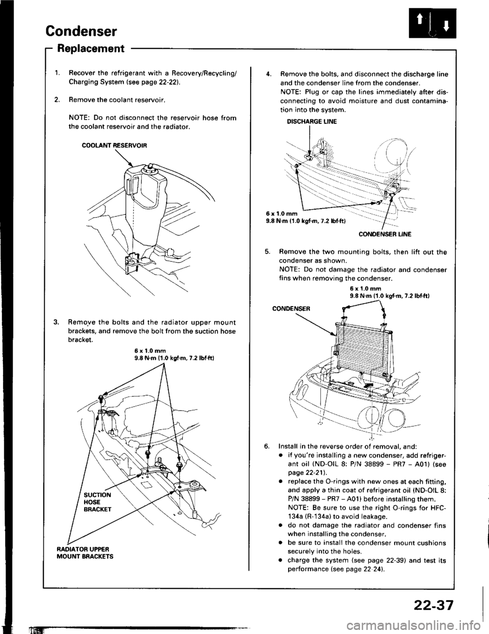
Condenser
Replacement
RAOIATOR UPPENMOUNT BRACKETS
Recover the relrigerant with a Becovery/Recycling/
Charging System (see page 22-221.
Remove the coolant reservoir,
NOTE: Do not disconnect the reservoir hose from
the coolant reservoir and the radiator.
COOLANT RESERVOIR
Remo.ve the bolts and the radiator upper mount
brackets, and remove the bolt from thg suction hose
bracket.
9.8 N.m {1.0 kgf.m.7.2 lbtftl
'1Iffi
22-37
6x1.0mm9.8 N.m (1.0 kgl.m,7.2 lbt.ft)
......-.....
CONOENSER LINE
Remove the bolts. and disconnect the discharge line
and the condenser line from the condenser.
NOTE: Plug or cap the lines immediately after dis-
connecting to avoid moisture and dust contamina-
tion into the system.
DISCHARGE LINE
Remove the two mounting bolts, then lift out the
condenser as shown.
NOTE: Do not damage the radiator and condenser
fins when removing the condenser.
6x1.0mm9.8 N.m (1.0 kgf.m, 7.2 lbl.tt)
Install in the reverse order of removal. and:
. if you're installing a new condenser, add refriger-
ant oil (ND-OIL 8: P/N 38899 - PR7 - A01) (see
page 22-21t,.
. replace the O-rings with new ones at each fitting,
and apply a thin coat of refrigerant oil {ND-OIL 8:
P/N 38899 - PR7 - A01) before installing them.
NOTE: Be sure to use the right O-rings for HFC-
134a (R-134a) to avoid leakage.
a do not damage the radiator and condenser fins
when installing the condenser,
. be sure to install the condenser mount cushions
securely into the holes.
. charge the system (see page 22-39) and test its
performance (see page 22 24!�.
Page 1128 of 1413
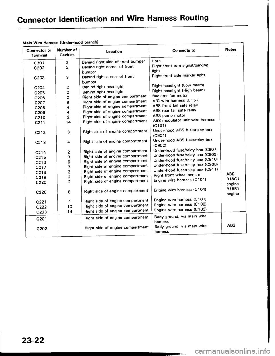
Connector ldentification and Wire Harness Routing
{Undor-hood
Horn
Right tront turn signal/Parking
light
Right Iront side marker light
Right headlight (Low beam)
Right headlight (High beam)
Radiator fan motor
A/C wire harness (C151)
ABS front fail saJe relay
ABS rear fail sate relay
ABS pump motor
ABS modulator unit wire harness
(c161)
Under-hood ABS fuse/relaY box
(c901)
Under-hood ABS fuse/relaY box
(c902)
Under-hood fuse/relay box (C907)
Under-hood tuse/relaY box (C909)
Under-hood fuse/relay box (C9l Ol
Under-hood fuse/relaY box (C908)
Under-hood fuse/relaY box (C91 1)
Right front wheel sensor
Engine wire harness {C 104)
Engine wire harness (C'l 04)
Engine wire harness (C101)
Engine wire harness (C l 02)
Engine wire harness {C 103)
Behind right side of tront bumper
Behind right corner of tront
bumper
Behind right corner of front
bumpet
Behind right headlight
Behind right headlight
Right side of engine comPartment
Right side of engine comPartment
Right side ot engine comPartment
Right side oJ engine comPartment
Right side of engine comPartment
Right side oJ engine comPartment
Right side of engine comPartment
Right side of engine comPartment
Bight side ot engine comPattment
Right side of engine comPartment
Right side of engine comPartment
Right side of engine comPartment
Right side of engine comPartment
Right side of engine comPartment
Right side of engine comPartment
Righl side ot engine comPartmenl
Right side of engine compartmenl
Right side of engine comPartmen'
Right side of engine comPartment
8
4
14
7
J
2
c201
c202
c203
c204
c205
c206
c207
c208
c209
c210
c211
c212
c213
c214
c215
c216
c217
c218
c219
c220
c220
c221
c222
c223
Body ground, via main wire
harness
Body ground, via main wire
harness
Right side of engine compartment
Right side of engine comPartment
23-22
Page 1158 of 1413
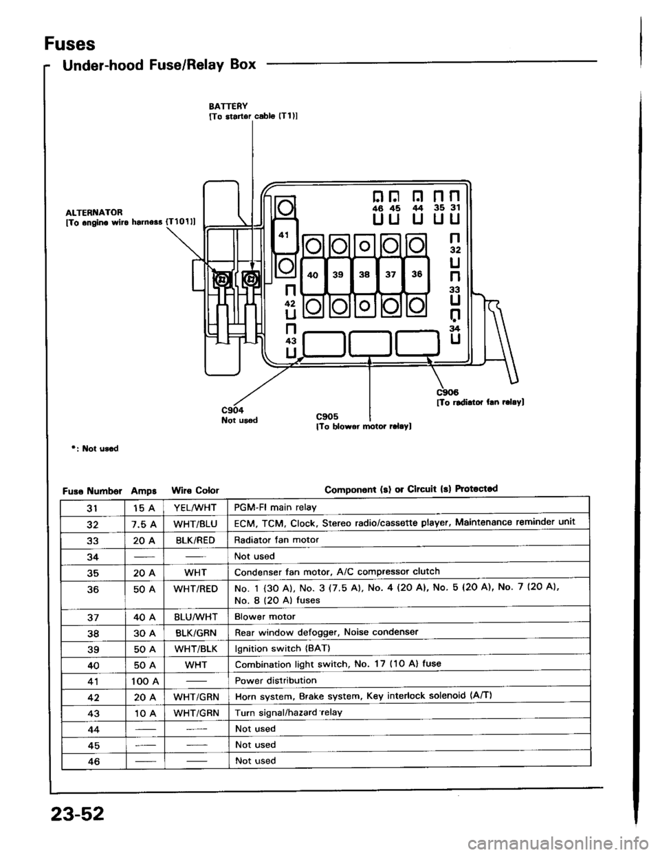
Fuses
Under-hood Fuse/Relay Box
ALTERI{ATOR
fTo .ngino wlto hsrno$ {Tlolll
Not usod
r: l\lot u3.d
umborAmpsColor
nF n nn46 45 /t4 35 3l
UU U UU
n32
U
n
33
U
r:rg
U
n
42
U
n43
U
[To rldidor hn r.l.Yl
Componon! (sl 01 Clrcuit 13) Protoqtod
3115 AYEL/WHTPGM-Fl main relay
327.5 AWHT/BLUECM, TCM. Clock, Stereo radio/cassette plsyer, Maintenance reminder unit
a2204BLK/REDRadiator Jan motor
34Not used
35204WHTCondenser fan motor, A/C compressor clutch
50AWHT/REDNo. I {3O A), No. 3 (7.5 A). No. 4l2O Al, No 5 (2O A), No. 7 (2O A),
No. I (20 A) fuses
3740ABLU/lVHTBlower motor
3830ABLK/GRNRear window defogger, Noise condenser
?q50AWHT/BLKlgnition switch {BAT}
4050AWHTCombination light switch, No. 17 (1O Al fuse
41100 APower distribution
4220AWHT/GRNHorn system, Brake system, Key interlock solenoid (Aff)
4310 AWHT/GRNTurn signal/hazard.elay
44Not used
45Not used
46Not used
23-52