Page 228 of 1413

Troubleshooting
Self-diagnostic Procedures (cont'dl
':818C1 engine
a lf codes other than those listed above are indicated, verifv the code. lf the code indicated is not listed above, replace
rhe ECM.
a The MIL may come on, indicating a system problem when, in fact, there is a poor or intermittent electricalconnection.
First, check the electrical connections, clean or repair connections it necessary.
o The MIL and @ indicator light may light simultaneously when the Diagnostic Trouble Code (DTC) 6, 7 or 17. Check
the PGM-Fl system according to the PGM-Fl system troubleshooting, then recheck the l!! indicator light. ll it lights,
see page 14-5O, 51.
a The MIL does not come on when there is a malfunction in the A/T Fl signal or Electrical Load Detector (ELDI circuits.
However, it will indicate the codes when the Service Check Connector is shorted.
DIAGNOSTIC
TROUBLE
CODE (DTCISYSTEM INDICATEDPsge
oENGINE CONTROL MODULE IECM)11-42
,lHEATED OXYGEN SENSOR IHO25)1 1-46
aMANIFOLD ABSOLUTE PRESSURE {MAP SENSOR)11-52
4CRANKSHAFT POSITION (CKP SENSOR)1 1-56
oENGINE COOLANT TEMPERATURE (ECT SENSOR)11-58
THROTTLE POSITION (TP SENSOR}11-60
ITOP DEAD CENTER POSITION (TDC SENSORI1 1-56
9No. 1 CYLINDER POSITION (CYP SENSOR)1 1-56
10INTAKE AIR TEMPERATURE (IAT SENSOR)11-62
13BAROMETRIC PRESSURE (BARO SENSOR}1|-64
14IDLE AIR CONTROL (IAC VALVE}11-42
tcIGNITION OUTPUT SIGNAL11-66
toFUEL INJECTOR1't-102
17VEHICLE SPEED SENSOR {VSSI11-68
20ELECTRICAT LOAD DETECTOR (ELD)'t 1-70
21VARIABLE VALVE TIMING & VALVE LIFT ELECTRONIC CONTROL SOLENOID
VALVE {VTEC SOLENOID VALVE)'6-36
22VARIABLE VALVE TIMING & VALVE LIFT ELECTRONIC CONTROL PRESSURE
SWITCH (VTEC PRESSURE SWITCHI-6-38
23KNOCK SENSOR {KS}-11-7 4
30A/T FI SIGNAL A11-76
3'rA/T FI SIGNAL B1 1-76
4'lHEATED OXYGEN SENSOR (HO25} HEATER11-47
43FUEL SUPPLY SYSTEM1 1-50
11-36
Page 267 of 1413

ldle Gontrol System
System Troubleshooting Guide
NOTE:
a Acrosa each row in the chan, the sub-systems that could be sources of a symptom are ranked in the order they should
be inspected, starting with O. Find the symptom in the left column, read across to the most likely source, then reler
to the page listsd at ths top ot that column. It inspection showa the system is OK, try the next system @, etc.
a lf the idle speed is out of sp€cification and th€ Malfunction Indicator Lamp {MlL) does not blink Diagnostic Trouble
Code (DTC) 14, 9o to inspection describ€d on pags 1 1-81.
PAGE
SYMPTOM
IDTIOJUSTIiSCREW
IDLE AIRc0NTROt-
AIRcoN0fTtoNtitcSIGNAL
ALTER.NAION FNSIGNAL
AUTOMATICIRAI{SA(LEGtARP0sm0 stGIAt
ERAK€swrTcHSIGNAL
STARTERswtTcHSIGNAT
POWERSTEERII'IGPffESSUREswncHSIGNAL
FAST IOLETHERMO
HOSESANOCONNEC.TIONS
11-9511-4211-841 1-8611-8811-9011-92I 1-9311-94
DIFFICULT TO STARTENGINE WHEN COLD@o
WHEN COLD FAST IDLE OUT OFSPEC l1,0OO- 2,0OO rpm|o@o
ROUGH IDLEo
WHEN WARM RPM TOO HIGHooo
WHEN
TOO LOW
ldl6 3p6od b b€lowspecitisd rpm (no loadl@o
ldla 5p66d doos nolincraas€ alter initialo
On mod6l3 with auto-matic transmBsion, thsidlo sp€ed drops in 963ro
ldl6 sp€eds drops when8ir condilioner in ONoo
ldls spo6d drops when6ts6iing wh66l i6 turninC@o
ldla spoed lluctust63with alactrical loado
FREOUENTSTALLING
WHILE WARMING UP@o
AFTER WARMING UPo@
FAILS EMISSION TESTo
11-78
.,Hilffirl|,
Page 270 of 1413
1. when the idls speed is out of specification and the Malfunction Indicator Lamp (MlLldoes not blink Diagnostic Trou-
ble Code (DTC) 14, check the tollowing items:. Adiust the idle speed {see page I1-95). Air conditioning signal (see page l1-84). ALT FR signal (see page '11-86)
A/T gea, position signal (see page 11-88)
Erake switch signal (see page 1 1-90)
Starter switch signal (see page 1l-921
PSP switch signal (see page 1 1-93)
Fast idl6 thormo valve (see page l1-94)
Hoses and connsctions
IAC valve and its mounting O-rings
2. lf the above items are normal, substitute a known-good IAC vslv€ and readjust the idle speed (see page 11-95)'
. It the idle speed srill cannot be adjusted to speciJication (and the MIL does not blink code 14) after IAC valve
roplacement, substitute a known-good ECM and recheck. It symptom goes away, replsce the original ECM.
1 1-81
Page 287 of 1413
Fuel Supply System
Fuel
NOTE:Check all fuel system lines and hoses for damage, leaks or deterioration, and replaco if n€cessery.
11-98
Page 289 of 1413

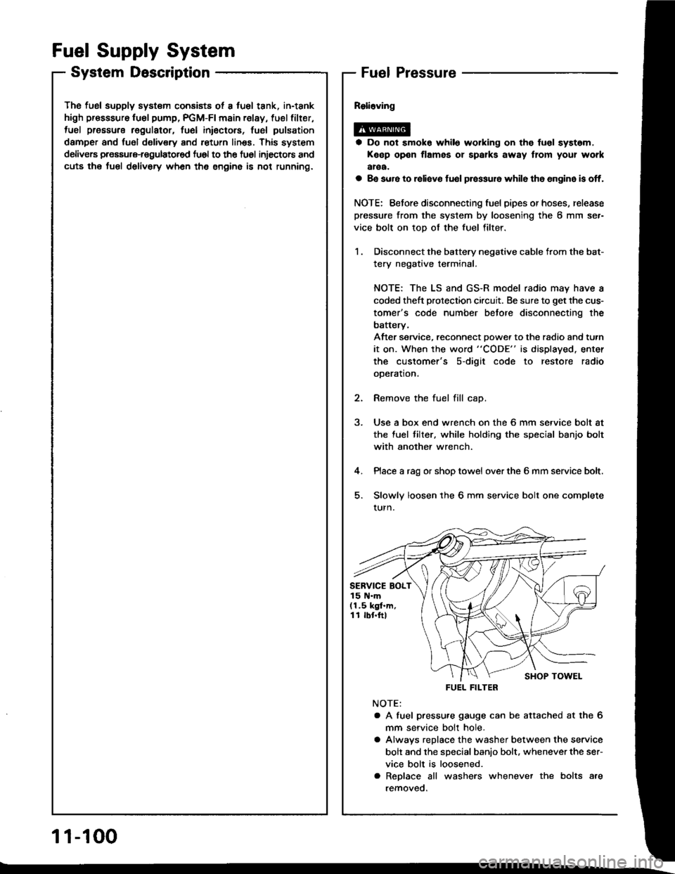
The fusl supply system consists ot a fuel tank, in-tank
high presssure fu6l pump, PGM-FI main relay, fuel filter,
tuel pressure regulatot, fuel inioctors, fusl pulsation
damper and fuol delivery and return linss. This system
delivers pressure-regulatored fu6l to the fu6l injectors and
cuts the fuel delivory wh6n the engine is not running.
Fuel Supply System
System DescriptionFuel Pressure
a Do not smok6 while working on the fuol syst6m,
Keep open flames or spalks away tlom your work
aroa.
a 8e sure to raliavo fuol p.essur6 while th6 6n9in6 is off.
NOTE: Eefore disconnecting fuel pipes or hoses, release
pressure from the system by loosening the 6 mm se.-
vice bolt on top of the fuel filter.
1 . Disconnect the battery negative cable from the bat-
tery negative terminal.
NOTE: The LS and GS-R model radio may have a
coded theft protection circuit. Be sure to get the cus-
tomer's code number betore disconnecting the
batterv,
After service, reconnect Dowe. to the radio and turn
it on. When the word "CODE" is displayed. enter
the customer's s-digit code to restore radio
ooeration.
2. Remove the fuel fill cap.
3. Use a box end wrench on the 6 mm service bolt at
the fuel tilter, while holding the special banjo bolt
with another wrench.
4. Place a rag or shop towel over the 6 mm service bolt.
5. Slowly loosen the 6 mm service bolt one complete
turn.
NOTE:
a A fuel pressu.e gauge can be attached at the 6
mm seryice bolt hole.
a Alwavs replace the washer between the service
bolt and the special banio bolt. whenever the ser-
vice bolt is loosened.
a Replace all washers whenever the bolts are
removeo.
SERVICE BOLT15 N.m(1.5 kgf.m,11 rbr.ftl
FUEL FILTER
1 1-100
Page 290 of 1413

Insp6ction
1. Relieve fuel pressure (see page 11-1OO)
2. Remove the service bolt on the tueltilter while hold-
ing the banjo bolt with another wrench. Attach the
special tool
3. Siart the engine. * Measure the {uel pressur€ with
the engine idling and vacuum hose of the fuel pres-
sure regulator disconnected from the tuel pressure
regulator and pinched.
Pressure should b€;
818B1 engins:
275-324 kPa (2.8-3.3 kgl/cm2, 40-47 psil
818C1 ongine:
329-37a kPa (3.35-3.85 kgf/cmz, 48-55 pei)
4. Reconnect vacuum hose to the tuel plessure
regulator.
Prossuro should b€;
Bl8Bl ongino:
216-245 kPa (2.2-2.5 kgf/cm'�, 31 -36 psil
B18Cl on9in6:
27O-319 kPa 12.75-3.25 kgt/cm'�, 39-46 psi)
FUEL PRESSURE GAUGE07406 - OO4000 1
lf the engine will not stan, turn the ignition switch
on. wait for two seconds, turn it off, then back on
again and read the fuel pressure.
CLAMP
a lf the fuel pressure is not as specified, first check the
fuel pump (see page 1 l - 1 1O). lf the fuel pump is oK,
check the following:
- lf the fuel pressuro is higherthan specified, inspect for:
. Pinched or clogged tuel return hose or line.
. Faulty fuel pressure regulator (see page 11-106)
- It the fuel p.essu.e is lower than specitied, inspect fo.:
. Clogged fuel tilter.. Faulty fuel pressure regulator (see page '11-106).
. Leakage in the fuel line.
1 1-101
Page 294 of 1413

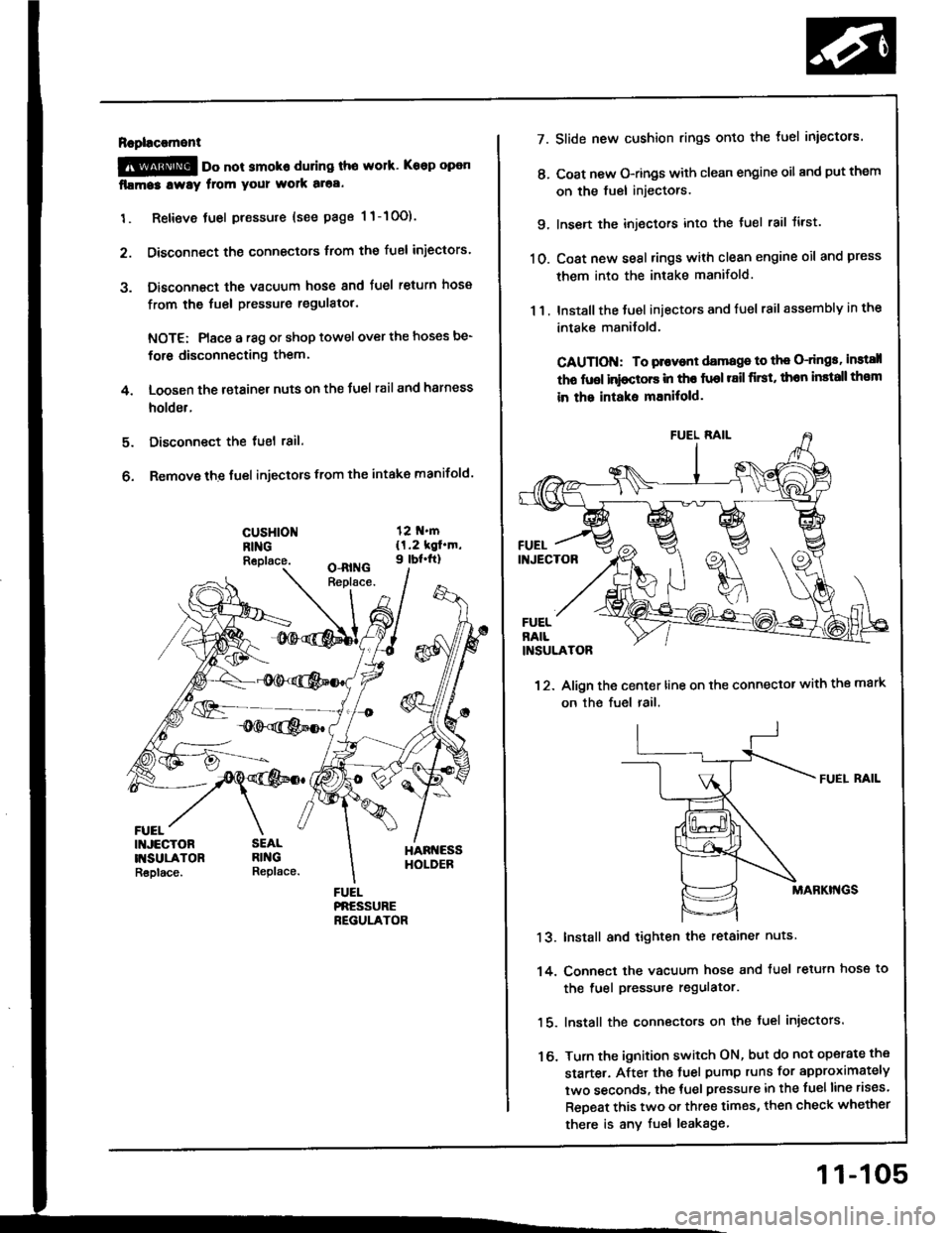
Rapl!c!ment
@ oo not smoko during tho work. Keep open
fllma3 lway from your wolk aloa.
1. Retieve tuel pressure {see page 1 1-10O).
2. Disconnect the connectors trom the fuel iniectors.
3. Disconnect the vacuum hose and fuel return hosa
from the fuel pressure regulatol.
NOTE: Place a r8g or shop towel over the hoses be-
for6 disconnecting them.
4. Loosen the retainer nuts on the Juel rail and harness
holder.
Disconnect the tuel 18il.
Remove the fuel injectors from the intake manifold.
5.
6.
cusHloNRINGReplace.
FUEL
7.
t'.
9.
10.
13.
14.
16.
11.
Slide new cushion rings onto the luel iniectors.
Coat new O-rings with clean engine oil and put them
on the fuel injectors.
Insen the injectors into the tuel rail tirst.
Coat new seal rings with clean engine oil and press
them into the intake manifold.
Install the Juel iniectors and fuel rail assembly in the
intake manilold.
CAUTION: To plovont damage to th€ O-dngs, instsll
tho fuol inioctors in tho fuol r8il first, thon install th€m
in the intaks mEnitold.
12. Align the center line on the connector with the mark
on the fuel rail.
FUEI. RAIL
MABKI'{GS
Install and tighten the retainer nuts
Conn€ct the vacuum hose and tuel retuln hose to
the fuel pressure regulator.
lnstall the connecto.s on the fuel injectors.
Turn the ignition switch ON, but do not operate the
starte.. After the tuel pump runs for approximately
two seconds, the tuel pressure in the fuelline rises.
ReDeat this two or three times, then check whether
there is any fuel leakage
11-105
Page 295 of 1413

Fuel Supply System
Fuel Pressure Regulator
FUELRETURI{
Description
The fuel pressure .egulator maintains a constant Juel
pressure to the tuel injectors. When the difference be-
tween the fuel pressure and manitold pressur€ exceeds
3.O kgf/cm'� 1294 kPa, 43 psi) tB18C1 engine: 3.5
kgt/cm, (343 kPa, 50 psi)], the diaphragm is pushed up-
ward, and the excess fuel is fed back into the fuel tank
through the retufn line,
CLOSE:
DIAPHRAGM
__l FUEL INLET
INTAKEMA'{IFOLDVACUUM
DIAPHNAGM
/1-
\J FUEL INLET
11-106
Te6ting
@ oo not smoko during the t€st. Ko6p opon
flames away from your work area,
1. Attach a fuel pressure gauge to the se.vice port of
the luel filter {see page 11-101).
Prossuro should be;
Bl88l ongin€:
275-324 kPa (2.8-3.3 kgf/cm', 40-47 psil
B18Cl €ngino:
329-378 kPa (3.35-3.85 kgf/cm'�.48-55 pEi)
(with tho tuol pressure rsgulator vacuum hoso dls-
connoctod and pinched)
FUEL PRESSURE GAUGE07406 - oO/IOOO 1
Reconnect the vacuum hose to the fuel pressure
regulator.
Check that the tuel pressure rises when the vacu-
um hose from the fuel pressure regulator is discon-
nected again.
a lf the fuel pressure did not rise, replace the fuel
pressure regulatot.