Page 326 of 1413
#7 VACUUM HOSE
Troublclhooting
VACUUM PUMP/GAUGEA973X-O41-XXXXX
EVAP PTJBGE COI{TROLDIAPHRAGM VALVE
EVAPPUBGE CONTROL
Bl8Bl .noin.:YEL/BLK I+I
(-t
wirg aide
--\
EVAPR'RGE COI{TROLSOLENOID VALVE
(cont'd)
VALVE
YEL/BLK (+I
Disconn€ct #7 vacuum hose
trom the EVAP putgo control di'
aph.agm valve lon the EVAPcon-
t.ol canistor) and connoct a
vacuum gauge to tho hose.
Stsrt the €ngine and allow it toidls.NOTE: Engine coolant tempera-
ture must be b€low 163oF (73ocl
Oisconnect the 2P connegtor trom
the EVAP purge control solenoid
Mea suro voltago betw€enYEL/BLK {+) terminsl 6nd RED
l-) terminal.
Inapact vacuum hoa€ror.ring.l| OK, toolrc. EVAPpurgo conttol solenoidls ther6 battery voltage?
Moasule voltage botweenYEL/BLK {+) terminal bodYground.
(To pa96 1 1- 138)
(To page 1 'l -139)
11-137
Page 412 of 1413
Description
Electronic Control System (cont'd)
. GRADE LOGIC CONTROL SYSTEM
How it works:
The TCM compares actual driving conditions with driving conditions memorized in the TCM. based on the input trom
the vehicle speed sensor, throttle position sensor, engine coolant temperature sensor, brake switch signal and select
lever position signal, to control shifting while a vehicle is ascending or descending a slope. or reducing speed.
SIGNALS DETECTED
Dliving ResistanceJudgement of Controlling Area
Engine Coolant
TemDerature Sensor
. Flat road mode. Asconding mode
(Fuzzy logic). Gradual Ascending
mode. Steep Ascending
14-20
Page 437 of 1413
Component Location
)/
,/s\
{7v
A0t
AUTOMATIC TRANSAXLE IA/TIGEAR POSITION SWITCH
VEHICLE SPEEDSENSOR {VSSI
COUNTERSHAFTSPEED SEf{SORMAINSHAFT SPEEDSENSORTHROTTLE POSITION (TP}SENSOR
at
,
)''ENGINE COOLANT TEMPERATURE (ECTISENSOR
14-45
Page 443 of 1413

Number of @indicator light
blinks while
Service Check
Connector is
connected with
the special tool.
@ indicator
lightPossible CauseSymptomRefer to
page
'loBlinksDisconnected engine coolant tempera-
rure (ECT) sensor connector
Short or open in ECT sensor wire
Faulty ECT sensor
Lock-up clutch does not
engage.14-68
1lOFFDisconnected ignition coil connector
Short or open in ignition coil wire
Faulty ignition coil
. Lock-up clutch does not
engage.'t 4-7 0
13Blinks. Shon or open in LT GRN wire between
the D3 terminal and ECM. Faulty barometric pressure {BARO)
sensor
NOTE: The BARO sensor is built into
the ECM
. No specific symptom
appears.
14-7 1
14Blinks. Short of open in FAS {YEL} wire be-
tween the D16 terminal and ECM. Faulty ECM
. Transmission jerks hard
when shitting.
't5OFFDisconnected mainshaft speed sensor
connecror
Short or open in mainshaft speed sen-
sor wire
Faulty mainshaft speed sensor
. Transmission jerks hard
when shifting.
14-75
SymptomProbable CauseRet.page
LQ! indicator light is on steady, not blinking whenever the ignition is on.14-77
[Q3] indicator light does not come on for 2 seconds after ignition is first
turned on.14-78
Lock-up clutch does not have duty operation (ON-OFFI.Check A/C signal with
A/C on.14-80Lock-up clutch does not engage.
Shitt leve. cannot be moved lrom @ position with the brake pedal
depressed.Check brake switch signal,14-41
It the self-diagnosis LQ4 indicator light does not blink, perform an inspection according to the table below.
a lf a customer describes the symptoms for codes 3, (yet the LQ! indicator light is not blinkingl, 6, 1 1 or 15, it will
be necessa.y to recreate the symptom by test driving. and then checking the @ indicator light with the ignition still
oN.
e lt ttre @ indicator light displays codes olher than those listed above or stays lit continuously, the TCM is faulty.. Sometimes the Lqd indicator light and the Malfunction Indicator Lamp (MlL)/Check Engine light may come on simul-taneously. lf so, check the PGM-Fl system according to the numbe. of blinks on the MIL/Check Engine light. thenreset the memory by removing the BACK UP fuse in the unde.-hood fuse/relay box for more than 1O seconds. Drive
the vehicle for several minutes at speed over 30 mph (5O km/h), then recheck the MIL/Check Engine light.
NOTE:
. PGM-FI system
The PGM-Fl system on this model is a sequential multiport fuel injection system.a Disconnecting the BACK UP luse also cancels the radio anti-theft code. preset stations and the clock setting. Get
the fuse so vou can reset them.the customer's code number and make note ot the radio
14-51
Page 460 of 1413
Electrical Troubleshooting
Troubleshooting Flowchart (cont'dl
Possibl€ Caus6
. Disconnoct€d engine coolantt€mp€rature (ECTI sensor con-noctor. Short or open in the ECT sensor
. Faulty ECT s€nsor
Self-diagnosis E indicator lightblinks ten times.
Turn the ignition switch ON.
Check whether the MalfunctionIndicator Lamp {MlL} blinks (seesection 1 1)-
ls the MIL blinking?Rop.ir tho PGM-FI Syrt.m (!go
!.ction 111.
Turn the ignition switch OFF.
Disconnectthe 26P and 22P con-nectors trom the TCM.Connect the Test Harness "A"
and "D" conneclors to the wireharness only, not to the TCM (seepage 14 49).
Measure the voltage between theD'18 and A25 or A26 lorminals.
Bopair op.n or .hofi In WHT/BLKwiro botwoon tho O18 tanni.|al.nd the ECM.ls the voltage 4.75-5.25 V?
Turn the ignition switch OFF.
oooooooooooo
ooooooooooooooooooooooo
oooo o oo o
Dlal + I
Page 1045 of 1413

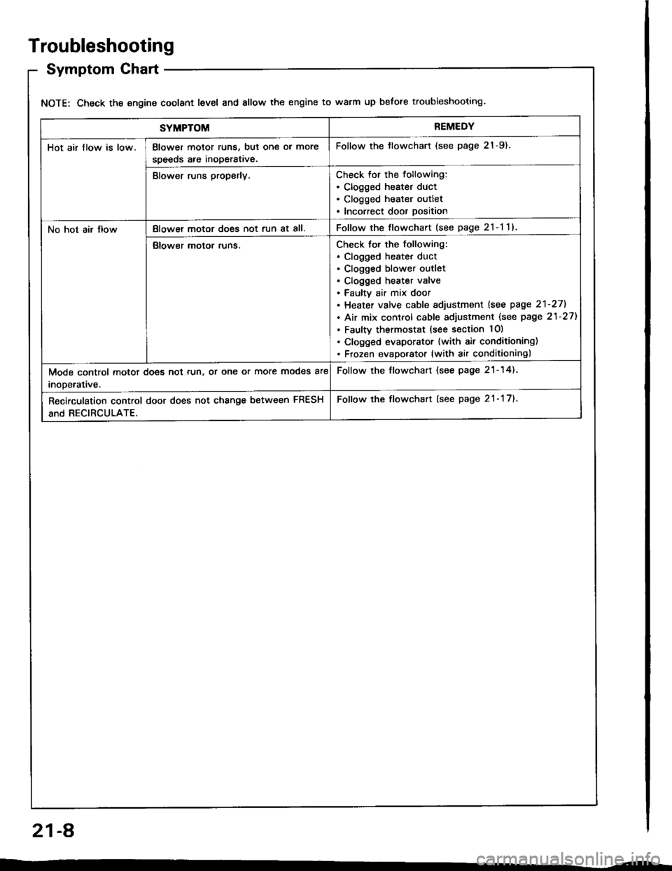
Troubleshooting
Symptom Chart
NOTE: Check the engine coolant level and allow the engine to warm up before troubleshooting.
SYMPTOMREMEDY
Hot air flow is low.Blower motor runs, but one ol more
speeds are inoperative.
Follow the tlowchart (see page 21-9).
Blower runs properly.Check for the following:. Clogged heater duct. Clogged heater outlet. Incorrect door position
No hot air JlowBlowel motor does not run at all.Follow the flowchart (see page 2l-l1l
Blower motor runs.Check for the following:. clogged heatet duct. Clogged blower outlet. Clogged heater valve. Faultv air mix door. Heater valve cable sdjustment lsee page 2'l-271
. Air mix control cable adjustment (see page 21-27)
. Faulty thermostat (see section lO)
. Clogged evaporator (with air conditioning). Frozen evaporator (with air conditioning)
Mode control motor does not run, or one or more modes are
inooerative.
Follow the flowchart (see page 21-14).
Recirculation control door does not change between FRESH
and RECIRCULATE.
Follow the flowchart (see page 21- 17).
21-A
Page 1059 of 1413

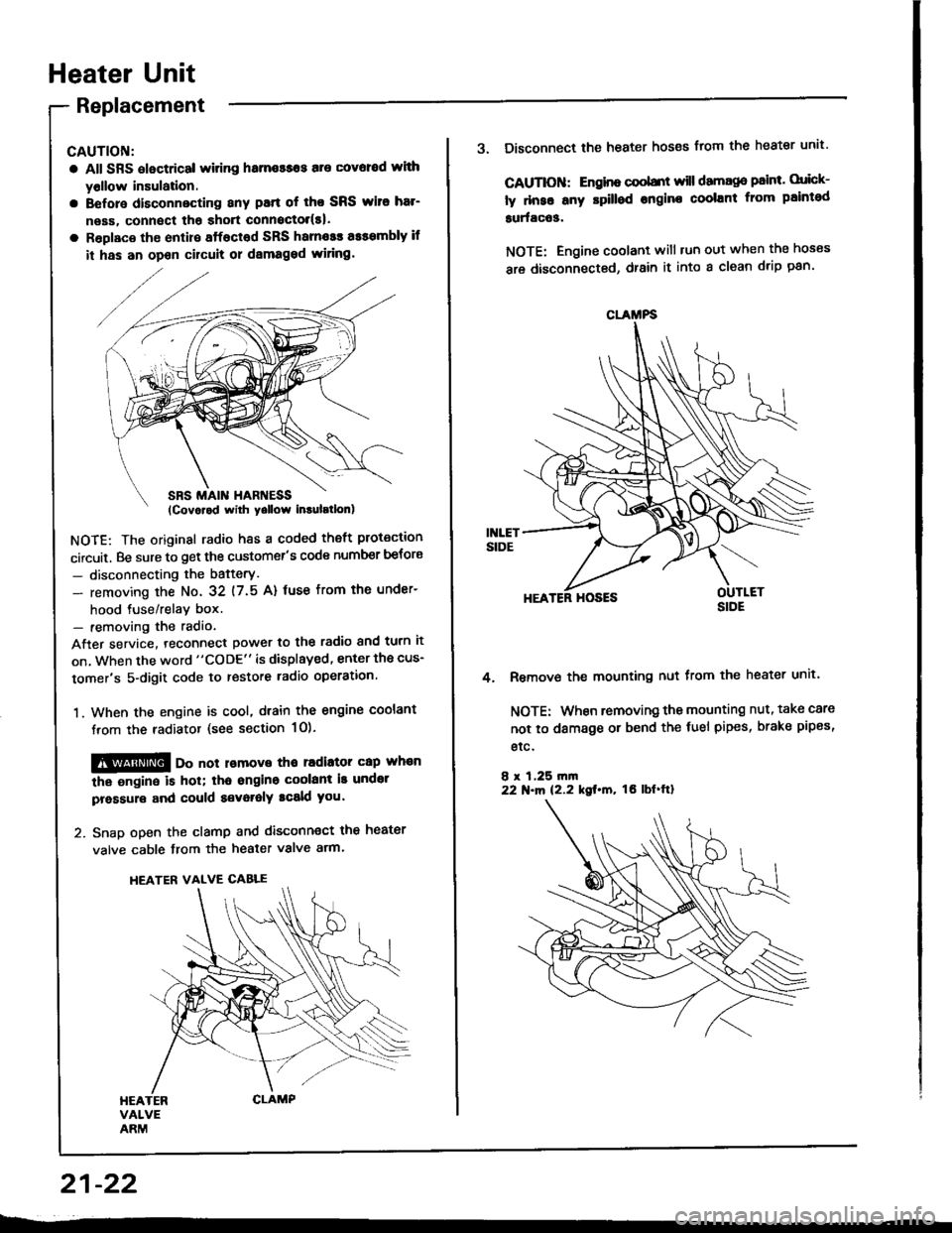
Heater Unit
Replacement
CAUTION:
a All SRS electrical witing hame$os are covoed wlth
yollow insulation.
a Before disconnecting any patt of tho SRS wito har-
neas, connect tha shott connoctol(s|.
a Roplaco th€ enlire sffacted SRS harnosr a$smbly if
it has an opon cilcult or dsmaged wiring.
NOTE: The original radio h8s a coded theft protection
circuit. Be sure to get the customer's code number betors
- disconnecting the bafterY.
- removing the No. 32 (7.5 A) fuse from th€ under-
hood tuse/relav box.- removing the radio
After service. teconnect power to the radio and turn it
on, when the word "CODE" is displayed, enter the cus-
tomer's 5-digit code to restore radio operation.
1. When the engine is cool, dtain the engine coolant
from the radiator (see section 1O).
@@ oo not lomove tho radiator cap whan
the ongine is hol; tha ongino coolant is undot
pressure and could a€voralY tcald you.
2. Snap open the clamp and disconnect the heater
valve cable from the heater valve arm.
HEATER VALVE CABLE
21-22
CLAMFS
3. Disconnect the heater hoses from the heater unit'
CAUTIOII: Engino coobnt will damago paint. orick-
ly dnse any rpilled engine coolant from paintod
surfac63.
NOTE: Engine coolant will tun out when the hoses
are disconnected, drain it into a clean drip pan'
HEATER HOSES
Remove the mounting nut from the heater unit.
NOTE: When removing the mounting nut, take care
not to damage or bend the fuel pipes, brake pipes,
etc.
8 r 1,25 rn|n22 N.m 12.2 kgt.m, tO lbf'ftl
4.
Page 1060 of 1413
5.
6.
7.
Rsmove the dashboard (see section 2O).
Remove the heater duct (see page 21-20) or theevaporator lse€ page 22-26).
Rsmove the two bolts, nut and the passenger,s SRS(}eam.
PASSEIVGER'SSRS EEAM
Disconnect the mode control motor conngctor, andremove the wire harness clip from the h€8ter unit.Remove the two mounting nuts and the haater unit.
6 r 1.0 mm9.8 .m (l.O kgt.m, 7.2 tbt.frl
MODE COI{TROL I,IOTORcol{t{€cToF
8.
8 x 1,26 mln22 N.m 12.2 kgf.m, 18 tbt.ttl
9. Install in the reverse order of removal, and:
a apply sealant to the grommets.a do not int6rchange the inlet and outl€t hoses.Make sure that the hose clamps are secure.a loosen th€ ble6d bolt on th6 engine and r€fillthetadiator and coolant r€servoir with the propsr en_gine coolant mixture (sse section 1O).Tighten the blsed boh when all the trapped air has6sc8p6d and engine coolant begins to flow fromit (see section 1O).a connect all csbles and make sure they 8re properlyadiusted (see pdge 21-271.
21-23