Page 967 of 1413
Headliner
Replacement
CAUTION: Whon Fyhg with I flat tip sclewdrivsr, wrap
it whh protectivs tapo to prevent damaga.
NOTE:
a Take care not to bend and scratch the headliner.
a Be caretul not to damage the dashboard and other in-
terior lrim.
a Fold the front seat-back backward.
Halchback
1. Remove;
. Door trim (see page 20-93)
a Front Dillar tirm {see page 20-91)
a Ouarter trim (see page 20-93)
a Coat hanger (see page 20-93)
a Rearview mirror {see page 20-52)
2. Remove the sunvisor and holder from each side.
: Scrow location!, 6
al
u)
LOCK WASHER(Outside)
"^/
HAaqr+- SUNV|SOR
Y
BRACKETHOLDEB
NOTE:
a lf necessary, remove the sunvisor bracket as
shown.
a When installing the sunvisor bracket, apply grease
and make sure it's installed properly.
suNvlsoRBRACKET
suNvrsoR
20-98
3. Remove the tront and rear ceiling lights, then dis-
connect the conneclors.
: Sc.ew, nut localions
A
: Scrcw, 2B
: Nut, 2
&)?)
HOOK
A
ffi)
LENS
HOOK
I
,r--T-\
m)
H
LENS
CONNECTOR
CONNECTOR
HOOKS
Page 993 of 1413

Garpet
Replacement
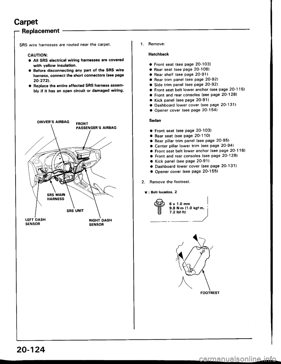
SRS wire harnesses are routed near the carpet.
CAUTION:
a All SRS slectrical wiring harn€ssos al€ covorod
with yollow insulation.
a Belore disconn€cting 8ny patt of th€ SRS wite
harness, connoct th€ short connectors {see pago
20-2721.
a ReDlace the €ntire affected SRS haln€sa assam-
bly if it has an opan cilcuit or damaged wiring.
ORIVER'S AIRBAG
1. Remove:
Hatchback
a Front seat (see page 2O-103)
a Rear seat (see page 20-108)
a Rear shell {see page 2O-91}
a Rear trim panel {see Page 20-921
a Side trim panel (see page 20-92)
a Front seat belt lower anchor (see page 20-115)
a Front and rear consoles (see page 2o-128)
. Kick panel (see page 2O-91)
a Dashboard lower cover (see page 20-131)
a Opener cover (see page 20-154)
Sedsn
a Front seat (see page 20-103)
a Rear seat {see page 2O-1 10)
a Rear pillar trim panel (see page 20-95)
a Center pillar lower trim (see page 20-94)
a Front seat belt lower anchor {see page 20- 1 1 6l
a Front and rear consoles (see page 20-128)
a Kick panel (see page 20-91)
a Dashboard lower cover (see page 20-131)
o Opener cover (see Page 20-155)
2. Remove the footrest.
V : Bolt locatios, 2
FOOTREST
20-124
I
v
6 x 1.O mm9.8 N.m {'l.o7 .2 tbt.ftl
Page 995 of 1413
Carpet
Replacement (cont'd)
4. Remove the SRS unit covers.
> : Clip locations, 2
Cut tne @ ana @ areas in the carpet, then pull it
back, as shown.
SRS UNIT COVERS
SRS MAIN
20-126
PARKING BRAKE
Cut here.
6. Cut the carpet under the parking btake lever'
CARPET
7. Remove the dashboard center bracket and center
beam bracket.
V : Bolt locatlona
AV : Boll, 4
s x 1.2s mm I22 N.m I12.2 ksf m, I16 tbt.ftl /,/
B>: Bolt, 1
6x1.Omm I9.8 N'm tl.O kgl m, I
l:?'o'!"t -'/C> : goli, 2
6 x 1.0 ftm I9.8Nm I11.0 kst'm, i'1Y"!_/
Page 997 of 1413
Front and Rear Consoles
Replacement
SRS wire harnesses are routed near the front console.
CAUTION:
a All SFS electrical wiring harnesses aro coverod
with y6llow insulalion.
a Betore disconnecting any part of lho SRS wire
harness, connect th€ short connoctorc (so€ pago
20-272t.
a Replaco tho sntilo aftocted SRS halness assom-
bly it it has an opon circuit or damaged wlring.
FBONTPASSENGER'S AIRBAG
20-128
NOTE: Take care not to scratch the tront and rear con-
soles, and dashboard.
1. Remove the access cap.
CAUTION: liYhen prying with a flat tip scr€wd.lv€r,
wrap it with protoctivo tape to provent damag€.
ACCESS CAP
2. Remove the sctews.
v : Scraw loc€tlona
At : Scr.w, 2 Bv : Scrow, 2
E)
w)
Page 1000 of 1413

Dashboard
Component Removal/lnstallation
SRS wire harnesses are routed near the dashboard andsteering column.
CAUTION:
a All SRS olectrical wiring harnesses ar6 covolodwith yallow insulation.
a Betoro disconnecting any paft ot th6 SRS wiro
harn€ss, connoct th€ shoi connectots (s66 page
23-2721.
a Replaco th€ entire Itlocted SRS hsrness asaem-
bly il h has an open circuh or damagod wiring.
CAUTION: Whan prying with a flat tip scrowdiv... wrapit with protoctiv€ tape, and apply protectivo tapo a.oundth€ felatsd parts. to provent damag€.
Instiumont p8n6l, Dashboad lower covor. Knec bobtcframoval:
l. Lower the steering column.
2. Remove the screws and detach the cliDs, then re-
move the instrument panel.
3. Remove the coin oocket.
4. Remove the screws and detach the clips, then re-
move the dashboard lower cover.
Disconnect the connector.
: Scrawlocation3, 5
AIF|]A\g)
A i Clip locationg
AA: Cllp, 2 B> : Clip, 2
I l-l L'l| ,-__-, )
itrvi
) 4Z)
_:n,,4<-ft
INSTRUMENT PAI{EL
(cont'd)
COIN POCKET
20-131
Page 1001 of 1413

Dashboard
Component Removal/lnstallation (cont'dl
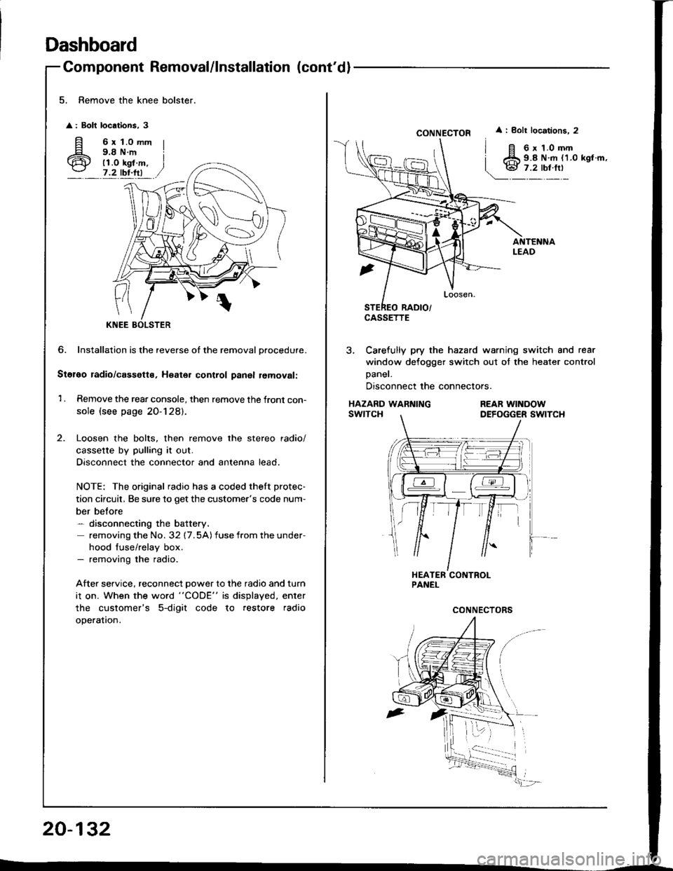
5. Remove the knee bolster.
: Bolt locations, 3
fi 6rt.omm
6 i;i'i#.,7.2 tbr.ftl
?
KNEE
6. Installation is the reverse of the removal Drocedure.
Stol€o radio/cassette, Heater control panal removal:
1 . Remove the rear console, then remove the front con-
sole (see page 20-128).
Loosen the bolts, then remove the stereo radio/
cassette by pulling it out.
Disconnect the connector and antenna lead.
NOTE: The original radio has a coded theft protec-
tion circuit, Be sure to get the customer's code num-
ber belore- disconnecting the battery.
removing the No. 32 17.5A) fuse from the under-
hood fuse/relay box.- removing the radio.
After service, reconnect power to the radio and turn
i1 on. When the word "CODE" is displayed. enter
the customer's 5-digit code to restore radio
operation.
20-132
CONNECTOR
CASSETTE
i Bolt locations. 2
6 x 1.0 mm9.8 N.m {1.0 kgl.m,
3, Carefully pry the hazard warning switch and rear
window defogger switch out of the heater control
Daner.
Disconnect the connectors.
HAZARD WARNINGswtTcHREAR WINOOWDEFOGGER SWITCH
Page 1003 of 1413
Dashboard
4.
20-134
Component Removal/lnstallation (cont'd
Side air vent .emoval:
Drivsi's
1. Remove the dashboard lower cover (see page
20-1 31 ).
2. Caretully pry the moonroof switch out of the side
air vent, then disconnect the connector.
MOONROOFswrTcH
CONI{ECTOR
SIDE AIRVENT
3, Remove the screw, then remove the side air vent.
< : Clip, hook locatlont
A< : Clip, 1
BV : Hook, 3
lnstallation is the reverse of the removal procedure.
NOTE: Make sure the connector is connected
properly.
> : Sc.6w location,
I
o@)
SIDE AIRVENT
Front passsng€r'�s
Careiully pry the side air vent at the lower edge, then
pull it out.
A : Clip, hook locationg
AA : Clip, 1BV : Hook, 2
Hi
1.'' 11 ,/
SIDE AIRVENT
PROTECTIVETAPE
Sido detoggor t m romoval:
Carefully pry the side detogger trim at the rear edge, then
remove rt.
A : Cllp, hook location!
AA : Clip,lB A: Hook, 1
PROTECTIVE
Page 1005 of 1413

Dashboard
Replacement Precautions
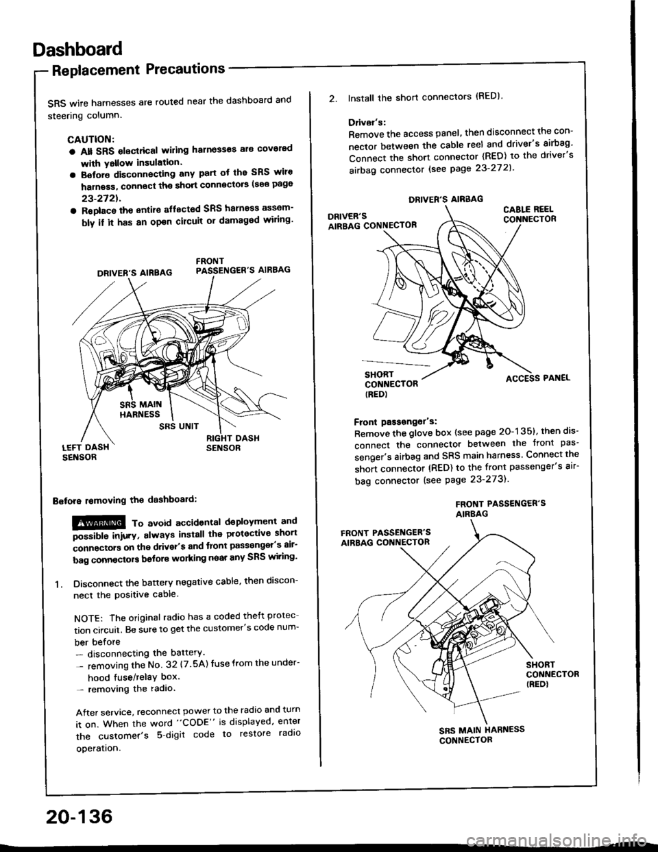
SRS wife harnesses are routed near the dashboard and
steering column.
CAUTION:
a Alt SRS olectrical wiling harness€s ale covorad
with Yollow insulation.
a Botore disconnecting any part ot the SRS wiro
harness, connect ths short connscto6 (see page
23-2721.
a Roplac6 ih€ entiro aflectod SRS halnoss assem-
bly il it has an opon cilcuit or damagod wiling'
LEFT DASHSENSOR
Bstora lomoving the dashboaid:
!@@ To avord accioenlal dsployment and
""iUU inir.v, always install the plotoctive short
;onnectors on the driver's and tlont pass€ngel's air-
bag connectors bolors working near any SRS wiring'
1. Disconnect the battery negative cable, then discon-
necl the positive cable.
NOTE: The original radio has a coded theft protec
tion circuit. Be sure to get the customer's code num-
ber before- disconnecting the battery.
- removing the No 32 (7.5A) Iuse from the under-
hood fuse/relaY box'- removing the radio.
After service, reconnect power to the radio and turn
it on. When the word "CODE" is displayed, enter
the customer's 5 digit code to restore radlo
ooeration.
DRIVER'S AIREAG
SRS UNIT
20-136
DRIVER'S AIRBAG
2.lnstall the short connectors (RED)
Ddvar's:
Remove the access panel, then disconnect the con-
nector between the cable reel and driver's airbag'
Connect the short connector (RED) to the driver's
airbag connector lsee page 23-27 2l'
DRIVER'SAIRBAG CONNECTOB
CABLE REELCONNECTOR
SHORTCONNECTOR(RED)
Front passongor's:
Remove the glove box {see page 20-135}, then dis-
connect the connector between the tront pas'
senger's airbag and SRS main harness Connect the
short connector (RED) to the front passenger's air-
bag connector (see Page 23-273).
FROf{T PASSENGER'SAIRBAG
ACCESS PAI{EL
FRONT PASSET{GER'SAIRBAG CONNECTON
SHORTCONNECTOR(REDI
SBS MAIN HARNESS
CONNECTOR