Page 1177 of 1413
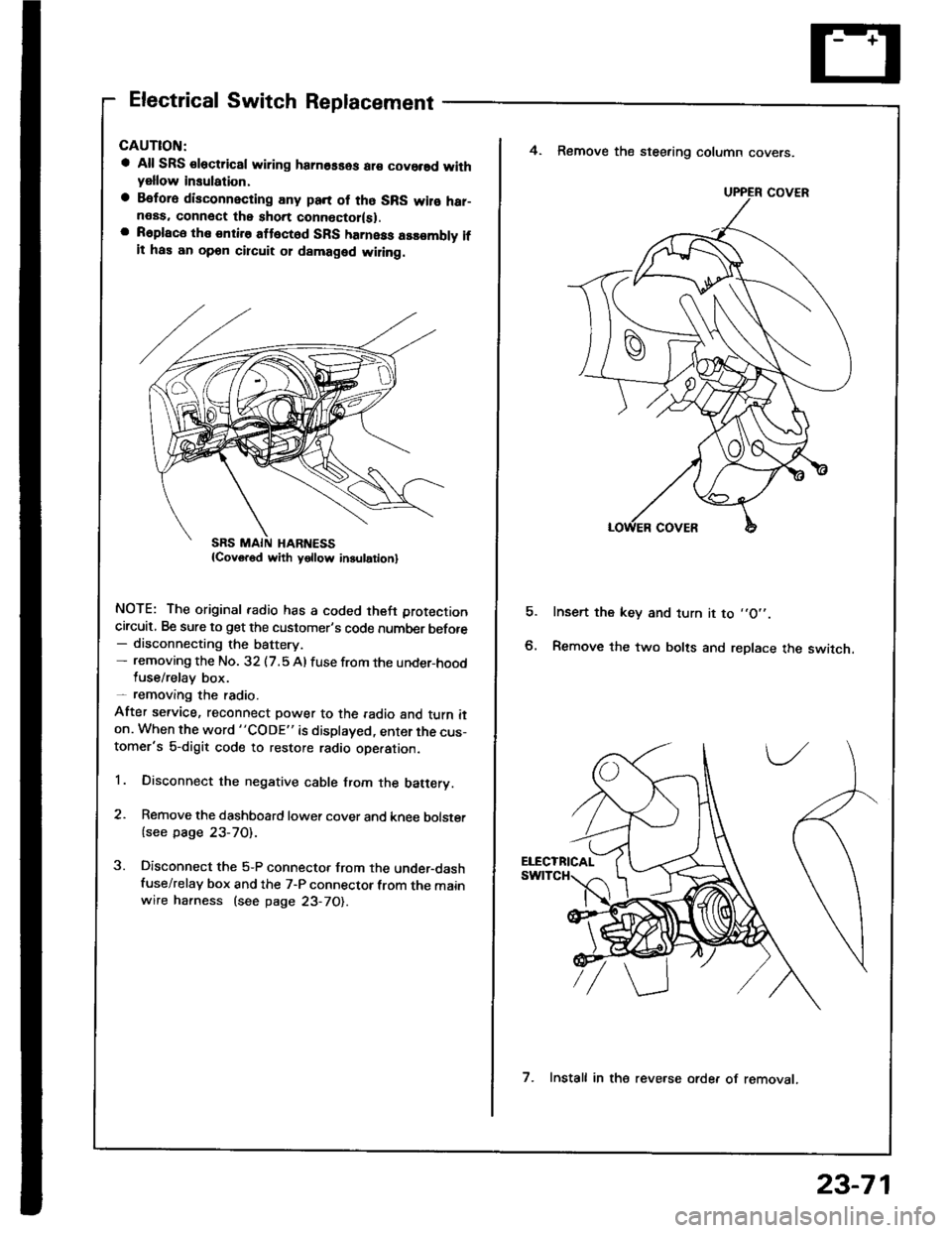
Electrical Switch Replacement
a All SRS €lectric8l wiring hamosses ar€ covorsd withyellow insulation,
a Befora disconnecting any pan of tho SRS wilo har-neas. connect the short connoctor(sl.a R6place the entire attect6d SFS harness assombly ifit has an opon circuit 01 damaged wiling.
NOTE: The original radio has a coded theft protection
circuit, Be sure to get the customer's code number before- disconnecting the battery.- removing the No. 32 (7.5 Al fuse from the under-hoodluse/relay box.- removang the radio.
After service, reconnect power to the radio and turn iton. When the word "CODE" is displayed, enter the cus-tomer's 5-digit code to restore radio ope.ation.
1. Disconnect the negative cable from the batery.
2. Remove the dashboard lower cover and knee bolster
{see page 23-70).
3. Disconnect the 5-P connector from the under-dashfuse/relay box and the 7-P connector from the mainwire harness (see page 23-70).
E
4. Remove the steering column covers.
Insert the key and turn it to ,,O',.
Remove the two bolts and replace the switch.
UPPER COVER
7. Install in the reve.se orde. of removat.
23-71
Page 1178 of 1413
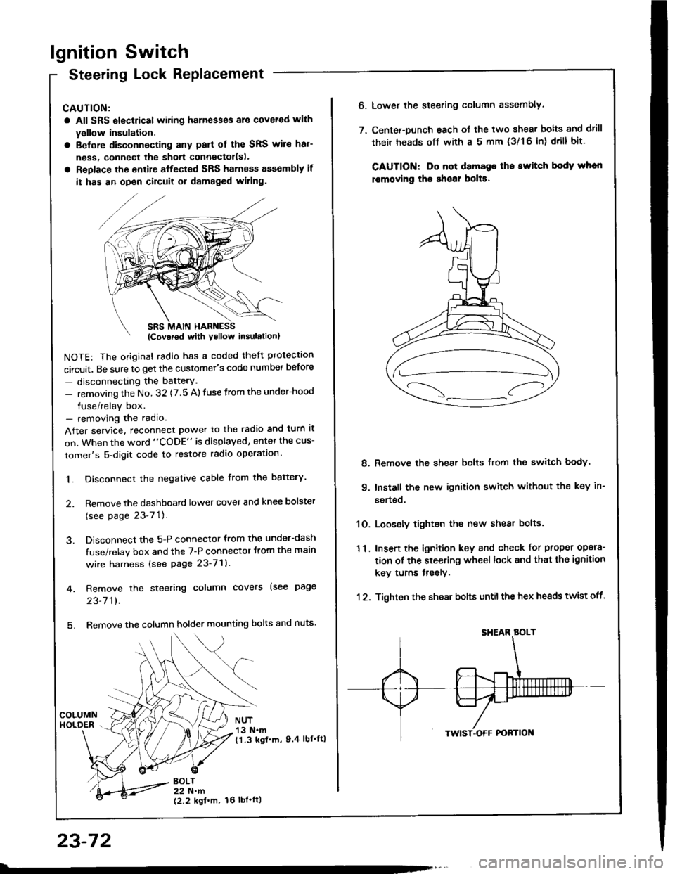
lgnition Switch
Steering Lock Replacement
CAUTION:
a All SRS electrical wiring harnesses ale covsred with
yellow insulation.
a Belore disconnecting any parl ot the SRS wir€ hal-
ness, connecl the short connector{s).
a Replace the entire alfected SRS harness a$6mbly il
it has an open circuit or damaged wiring.
NOTE: The original radio has a coded thett protection
circuit. Be sure to get the customer's code number betore
- disconnecting the batterY.
- removing the No. 32 (7.5 A) fuse from the under-hood
fuse/relay box.- removing the radio.
After service, reconnect power to the radio and turn it
on. When the word "CODE" is displayed, enter the cus-
tomer's 5-digit code to restore radio operation.
1. Disconnect the negative cable from the battery.
2. Remove the dashboald lower cover and knee bolster
(see page 23-7'l ).
3. Disconnect the 5-P connector from the under-dash
fuse/relay box and the 7-P connector trom the main
wire harness {see page 23-71).
4. Remove the steering column covers (see page
23-711.
5. Remove the column holder mounting bolts and nuts'
BOLT22 N.m
12.2 kgl'm.
NUT13 N.m(1.3 kgf.m, 9.4 lbl'ftl
23-72
16 tbt.ftl
6. Lower the steering column sssembly.
7. Center-Dunch each oJ the two shear bolts and drill
their heads off with a 5 mm {3/1 6 in) drill bit'
CAUTION: Do not dama96 tho switch body whon
r€movlng the shoar bol$.
Remove the shear bolts from the switch body.
Install the new ignition switch without the key in-
serted.
Loosely tighten the new shear bolts.
Insert the ignition key and check for proper opera-
tion of the steering wheel lock and that th€ ignition
key turns freely.
Tighten the shear bolts untilthe hex heads twist off.
8.
q
10.
11.
12.
Page 1183 of 1413
5. Check lor 8n op€n in the BLKMHT wire circuit be-
tween the staner and ignition switch, and con-
nectors.
6. Check the ignition switch (see page 23-70).
7, On cars with automatic transmission, check the A/Tgear position switch (neutral position switchl and
connector. On cars with manualtransmission, check
the staner cut relay, clutch interlock switch, and
connectors.
NOTE: Check the No. 39 (5O A) fuse in the under-hood
fuse/relay box for the starter cut relay.
Check tor Woar and Damago:
The starter should crank the engine smoothly and stead-
ily. lf th€ startsr engages, but cranks the engine errati-
cally, remove it. Inspect the starter, drive gear, and
flywheel ring gesr for damage.
a Check the drive gear overunning clutch for binding
or slipping when the armature is rotated with the drivegear held. Replace the gesrs if damaged.
Check Cranking Voltago 8nd Current Draw:
Cranking voltage should be no less than 8.O volts.
Current draw should be no more than 360 amperes.
lf cranking voltag€ is too low, or current draw too high,
check for:
a Fully charged battery
a Open circuit in starter armature commutatot segments
a Starter armature dragging
a Shoned armature winding
a Excessive drag in engine
Chack Cranking rpm:
Engine spsod during cranking should be above 1O0 rpm.
lf spe6d is too low, ch€ck for:
a Loose battsry or starter teminals
a Excessively worn starter brushes
a Open circuit in commutator segments
a Dirty or damaged helical spline or drive gear
a Defective drive gear overrunning clutch
Chock StErtor Disongagomoni:
Press the clutch pedal allth€ way in (M/T), turn the ioni-
tion switch to "lll" and rolease to "11".
The starter drive gear should disengage from the tlywheel
ring gear. When you rolease the key.
lf the drive gear hangs up on th€ flywheel ring gear, check
for:
a Solenoid plunger and switch malfunction
a Dirty drive gear assembly or damaged overrunning
clutch
23-77
Page 1244 of 1413
Interlock System
Component Location Index
All SRS electrical wiring harnass€s are covered with
yallow insulation.
Before disconnecting any part of the SRS wire har-
ness, connect the shon connector(sl.
Replace the entire affected SRS halness ass€mbly it
it has an open circuit or damaged wiring.
INTERLOCKCONTROLUNITfnput Test, page 23-141
SRS MAI[{ HARNESS
lcovorod with yellow insulstionl
SHIFT LOCK SOLENOIOTest, page 23- 143Repfacement, page 23-1 43
KEY INTERLOCK SOLENOIDsnd KEY INTERLOCK SWITCH(ln the steering lock assembly)Test, page 23-142
23-138
Page 1245 of 1413
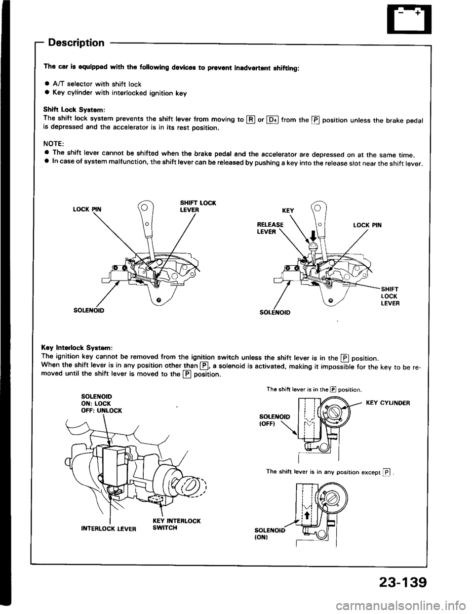
Descraption
The car is squippod with thq following dovlc6. to prevont inadvoft.nt shitting:
a A/T selector with shift locka Key cylinder with interlocked ignition key
Shift Lock Syst6m;
The shitt lock system prevents the shift lever from moving to @ or lDil from the @ position unless the brake pedalis depressed and the accelerator is in its rest oosition.
NOTE:
a The shift lever cannot be shifted when the brake pedsl and the accelerator are depressed on at the same time.a In case ot system malfunction, the shift lever can be released by pushing a key into the release slot near the shift lever.
Koy Ints.lock Systsm:
The ignition key cannot be removed from the ignition switch unless the shil-t lever is in the E positionWhen the shift lever is in any position other than @, a sol€noid is activated, making it impossible for the key to be re-moved until the shift lever is moved to the llj position.
SOLEI{OIDON: LOCKOFF: UNLOCK
Th€ shift lever is in the E position.
KEY CYLINDER
The shift lever is in any position except pl .
II{TERLOCK LEVERswtTcH
23-139
Page 1247 of 1413
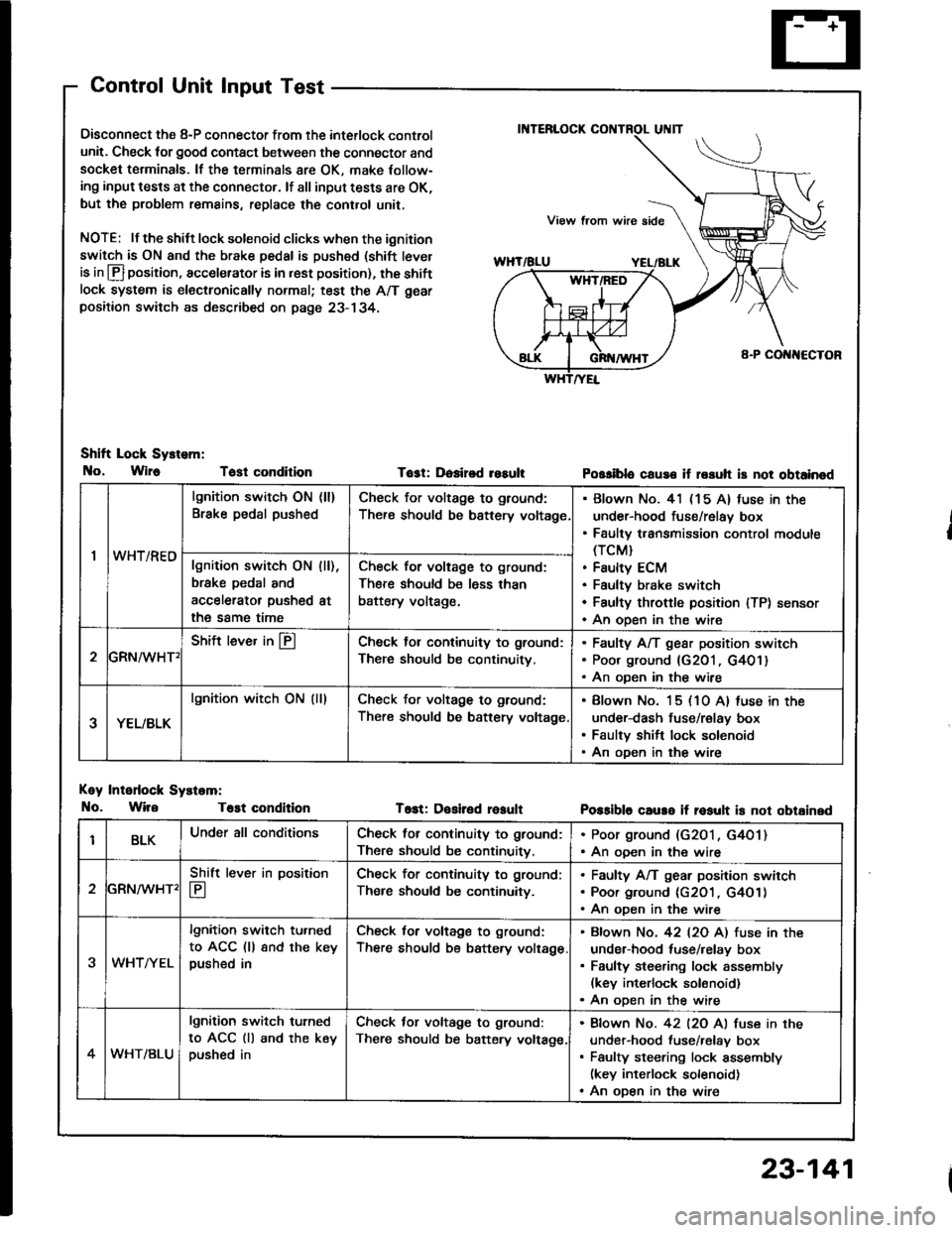
Control Unit Input Test
Oisconnect the 8-P connector from the interlock control
unit. Check for good contact between the connector and
socket terminals. lf the terminals 8re OK, make Iollow-
ing input tests at the connector. lf all input tests are OK,
but the problem remains, replace the cont.ol unit,
NOTE: lf the shilt lock solenoid clicks when the ignition
switch is ON and the brake pedal is pushed (shift tever
is in lfl position, accelerator is in rest position), the shiftlock system is electronically normal; test the A/T gear
positaon switch as described on page 23- 134.
Shift Lock Sy.tem:
No, Wlr6 Tost condition
Koy Intodock Systam:
No. WireT6st condition
Tost: Dosired resultPossiblo cause if rssuh is not obtainod
T6st: Desiled reaultPossible caure if rosult is not obtainsd
'I
lgnition switch ON (ll)
Brake pedal pushedCheck for voltage to ground:
There should be bsttery voltage
Blown No. 41 (15 A) fuse in the
under-hood fuse/relay box
Faulty transmission control module(TCM}
Faulty ECM
Faultv brake switch
Faulty throftle position lTP) sensor
An oDen in the wire
wn t/hEulgnition switch ON
brske pedal and
accelerator pushed
the same time
I [),
at
Check for voltage to ground:
There should be less than
battery voltage.
GRN^/vHT'
Shift lever in @Check lol continuity to ground:
There should be continuity.
Faulty A/T gear position switch
Poor ground {G201, G401}
An oDen in the wire
YEL/BLK
lgnition witch ON (lllCheck for voltage to ground:
There should be battery voltage
Blown No. 15 (10 A) luse in the
under-dash fuse/relay box
Faulty shift lock solenoid
An oDen in the wire
BLKUnder all conditionsCheck for continuity to ground:
There should be continuitv.
. Poor ground (G2O1, G4O1). An ooen in the wire
2
Shift lever in position
E
Check for continuity to ground;
Ther€ should be continuity.
Faulty A/T gear position swirch
Poor ground (c2O1 , G4O1)
An oDen in the wire
3WHTAYEL
lgnition switch tu.ned
to ACC (ll 8nd the keypushed in
Check for voltage to ground:
There should be battery voltage
Bfown No. 42 l2O Al fuse in the
under-hood tuse/relay box
Faulty steering lock assembly(kev interlock solonoid)
An oDen in the wire
4WHT/BLU
lgnition switch turned
to ACC (ll and the keypushed in
Check tor voltage to ground:
There should be batery voltage,
Bfown No. 42 l2O Al fuse in the
under-hood fuse/relav box
Faulty steering lock assembly(key interlock solenoid)
An oDen in the wire
23-141
Page 1248 of 1413
Interlock System
Kev Interlock SolenoidTestKey IntenocK Dorenoro I esr -
CAUTION:
a All SRS electrical wiring harnesses ar€ covered rYith
yollow insulation.
a 8eforc disconnecting any pan of the SRS wire har-
ness. connecl tha short connoclol{s|.
a Raplace the ontire affected SRS harness assembly if
it has an opon circuit or damaged wiring,
4. Check for continuitv between the terminals in each
switch position according to the table.
5, Check that the key cannot be removed when the bat-
tery is connected to the No. 6 8nd No. 7 terminals.
a It the kev cannot be removed, the key interlock
solenoid is OK.
a lf the key can be removed, replace the steering
lock assembly (key interlock solenoid is not avail-
able separately).
1.Remove the dashboard lower cover
Remove the knee bolster.
Disconnect
narness.
the 7-P connector from the main wire
\______________rry
Position7
lonitionS hch Acc
Koy push€d ino---o
Koy roleEsod r--o
* : l5-20ohms
{Covorod with yollow inlulrtionl
23-142
Page 1250 of 1413
Integrated Control Unit
Circuit Diagram
D.3c ptlon
An integrat€d control unit, located in the left kick panel, integratss the functions of tho keyin/seat beh r6mind€r, sido
markar light {lasher, wiper/washer, lights-on r6minder, rear window dsfogger timer, brak€ system light bulb check, and
enging oil pressure indicator flasher circuitE,
NOTE: Difforent wires with the same color have be6n given a numbor suffix to distinguish them (for Example,
GRN/RED1 and GRN/RED'� are not the same).
WNOSHIELD WIPER/WASHER SWITCH
IMT OFFiINT
I
II
IIIIIIIIIIII
YEUEE
rl
t
P
UNOER - DASH FUS€/RETAY BOX
r NTEGRATED COI{TROI UNIT
t-0wErGrilE 0|lPRESSI'REINDICATORLIGI{T
WINDSHIELOWIPERAVASHERswtTcH
tr-/
IBLK/GRN BI
WINDSHIELOWIPERMOTOR{Asl
VOLTAGEREGULATOR{ln ahamator,
UNOER- HOOD FUSE/RELAY 8OX
I
r3
r8relit;rBt5I
23-144
lr ) : With combinod washef-wip€r oporation