Page 561 of 1413
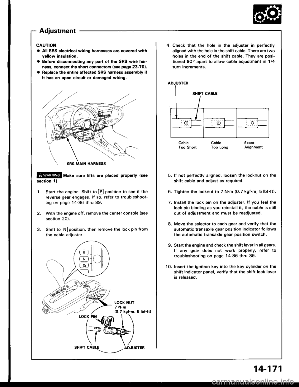
4. Check that the hole in the adiuste. in perfectly
aligned with the hole in the shift cable. There are two
holes in the end of the shitt cable, They are posi-
tioned 9Oo apart to allow cable adiustment in 1/4
lurn Incremenls.
ADJUSTER
CableI oo snonCableToo LongExactAlignment
5. It not perfectly aligned, loosen the locknut on the
shift cable and adjust as required.
6. Tighten the locknut to 7 N.m (O.7 kgf.m, 5lbf.ft).
7. Install the lock pin on the adiuster. lf you feel the
lock pin binding as you reinstall it, the cable is still
out of adjustment and must be readjusted.
8. Move the selector to each gear and verify that the
automatic transaxle gear position indicator tollows
the automatic transaxle gear position switch.
9. Start the engine and check the shift lever in all gea.s.
lf any gea. does not work properly, refer to
troubleshooting on page 14-86 thru 89.
1O. lnsert the ignition key into the key cylinder on the
shift indicator panel, ve.ify that the shift lock lever
is released,
CAUTION:
a All SRS electrical widng harn€sses are covar€d with
yollow insulation.
a Before disconnecting any part of ths SRS wire har-
ness, connect the shon connectors (see page 23-701.
a R€place the entire affected SRS halnass asssmbly it
it has an op€n circuit or damaged wiring.
@ tu"t" sure lifts a.e placed properly ls66
ssction 1).
Start the engine. Stritt to @ position to see if the
reverse gear engages. lf so, refer to troubleshoot-
ing on page 14-86 thru 89.
Wilh the engine off, remove the center console {see
section 20).
Shilt to N position. then remove the lock pin from
the cable adjuster.
'1.
/
''fidlfr
I
t+@
\/ \
CABLE-.'.-_--l../ADJUSTER
]H
@
@
@
Adjustment
14-171
Page 1075 of 1413
Troubleshooting
Reference Ghart
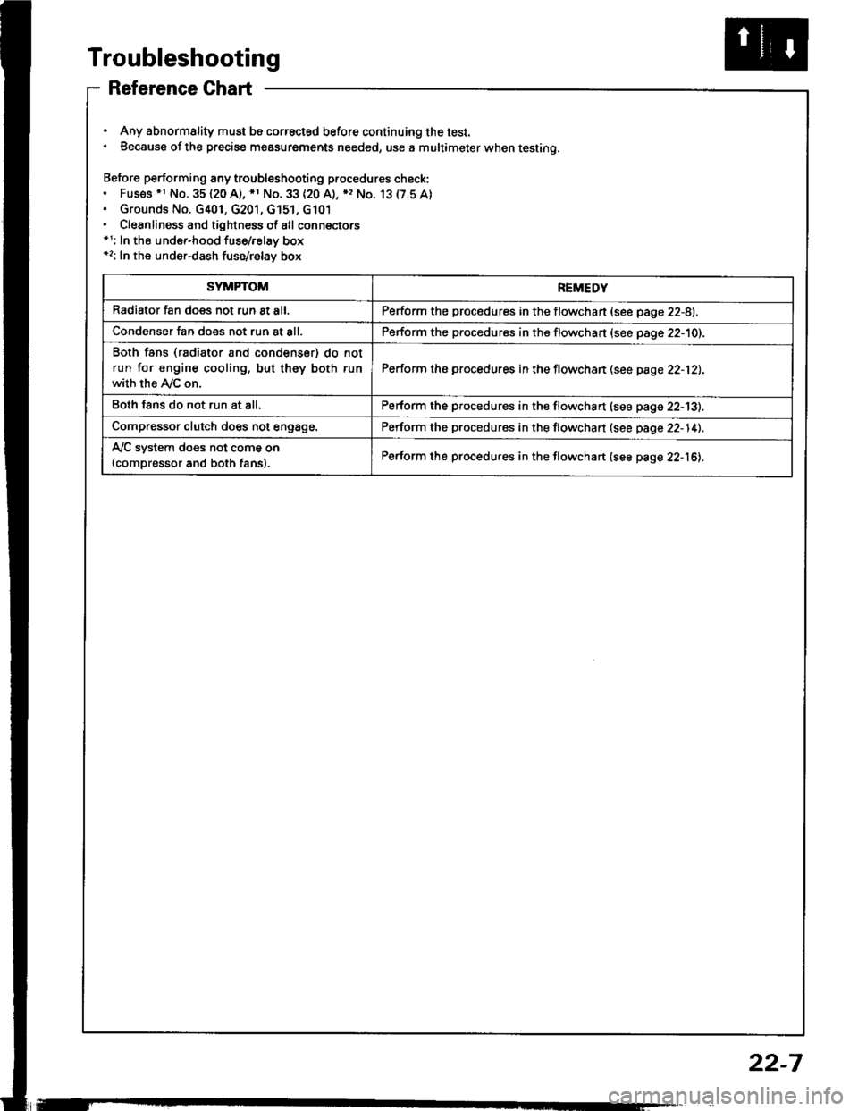
. Any abnormality must be correctsd before continuing the test.. Because of the precise measurgments needed, use a multimeter when testing.
Before performing any troubleshooting procedures check:. Fus€s .r No. 35120 A), *1 No. 33 (20 A), ), No. 13(7.5A). Grounds No. G401, G201, G'151, G101. Cleanliness and tightness of all connectors*1: In the under-hood fuse/relay box*2: In the under-dash fuse/relay box
SYMPTOMREMEDY
Radiator fan does not run 8t all.Perform the procedures in the flowchan (see page 22-8).
Condenser fan does not run at all.Perform the procedures in the flowchart (see page 22-10).
Both fans (radiator and condenser) do not
run for engine cooling, but they both run
with the Ay'C on.
Perform the procedures in the flowchan (see page 22-12).
Eoth fans do not run at all.Perform the procedures in the flowchart (see page 22-13).
Compressor clutch does not engage.Perform the procedures in the flowchart (see page 22-14).
Ay'C system does not come on
{compressor and both fans}.Perform the procedures in the flowchart (see page 22-16).
22-7
Page 1109 of 1413
Troubleshooting
Tips and Precautions
Before Troubloshooting
a Check applicable fuses in the appropriate fuse/relay
DOX.
a Check the battery for damage, state of charge, and
clean and tight connections.a Check the alternator belt tension.
CAUTION:
a Do not quick-charg€ a battery unless the batteryground cabla has be€n disconnoctsd. oth€rwisoyou will damage the alternator diodss.a Do not att6mpt to crank the engine with the bat-tery ground cable loosely connectsd or you will se-vorsly damag€ tho widng.
a The original radio has a codod thatt plotection ci.-cuit. Be sul€ to got tho customor's code numbet
before- disconnecting th€ battery.- lomoving tho No. 32 (7.5 Al tuso f.om the
under-hood tuse/lelay box.- removing tho radio.
Aflor s€lvic€. reconn€ct powet to tho radio and
turn it on. Whon the word "CODE" is displayed,
€nt€l the customer'E s-digit codo to .astore ladio
operation.
Handling Connectors
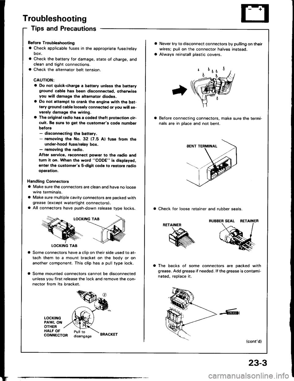
a Make sure the connectors are clean and have no loose
wire terminals.
a Make sure multiple cavity connectots are packed withgrease (except watertight connectors).a All connectors have push-down release type locks.
LOCKII{G TAA
LOCKING TAB
a Some connectors have a clio on their side used to at-
tach them to a mount bracket on the body or on
another component. This clip has a pull type lock.
a Some mounted connectors cannot be disconnected
unless you first release the lock and remove the con-
nector from its bracket.
LOCKINGPAWL ONOTHERHALF OFPull toorsengageCONNECTORBRACKET
23-3
a Never try to disconnect connectors by pulling on thei.
wires; pull on the connector halves instead.
a Always reinstall plastic covers.
Belore connecting connectors, make sure the lermi-
nals are in Dlace and not bent.
a Check tor loose retainer and rubber seals.
RETAINER
a The backs of some connectors are oacked with
grease. Add grease if needed. It the grease is contami-
nated, reDlace it.
(cont'd)
Page 1119 of 1413
Connector ldentification and Wire Harness Routing
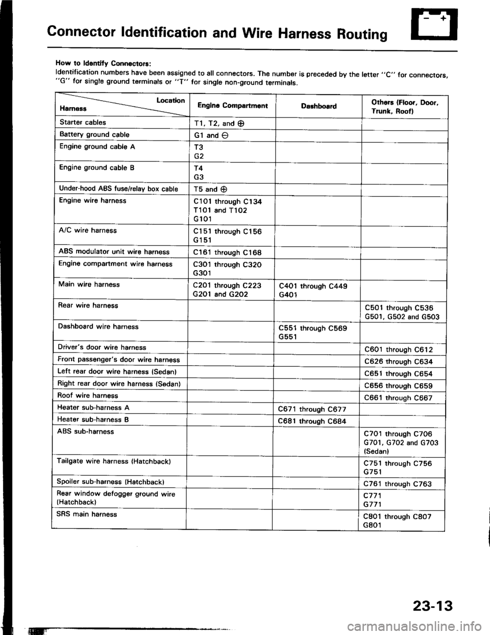
How to ldentity ConnoctolS:
ldentification numbers have been assigned to all connectors. The number is preceded by the letter ,,C,, for connecrors,"G" for single ground terminals ot "f" hr single non-ground terminals.
Location
HamessEngino CompartmontDarhboardOthors (Floor, Door,
Trunk, Rootl
Starter cablesT1, T2, and (E
Battery ground cableG1 and O
Engine ground cable AT3
Engine ground cable BT4
G3
Under-hood ABS fuse/relav box cableT5 and (D
Engine wire harnessC101 through C134
Tl Ol and T102
G 101
A/C wire harnessCl 5'l through C156
G151
ABS modulator unit wir€ harnessC161 through C168
Engine companment wire ha.nessC3O'l through C32O
G301
Main wire hatnessC2O1 through C223
G2Ol and G2O2
C4O1 through C449
G401
Rear wire harnessC501 through C536
G501, G502 and G5O3
DashboSrd wire harnessC551 through C569
G551
Driver's door wire harnessC601 through C612
Front passenger's door wire harnessC626 through C634
Left rear door wire harness (Sedan)C651 through C654
Right rear door wire harness (Sedan)C656 through C659
Roof wire harnessC661 through C667
Heater sub-harness AC671 through C677
Heater sub-hatness BC681 through C684
ABS sub-harnessC7O1 through C7O6
G7O1, G702 and G703(Sedan)
Tailgate wire harness (Hatchback)C751 through C756
Spoiler sub-ha.ness (Hatchback)C761 through C763
Rear window defogger ground wire(Hatchback)c77'l
G771
SRS main harnessC8O1 through C8O7
G801
23-13
Page 1183 of 1413
5. Check lor 8n op€n in the BLKMHT wire circuit be-
tween the staner and ignition switch, and con-
nectors.
6. Check the ignition switch (see page 23-70).
7, On cars with automatic transmission, check the A/Tgear position switch (neutral position switchl and
connector. On cars with manualtransmission, check
the staner cut relay, clutch interlock switch, and
connectors.
NOTE: Check the No. 39 (5O A) fuse in the under-hood
fuse/relay box for the starter cut relay.
Check tor Woar and Damago:
The starter should crank the engine smoothly and stead-
ily. lf th€ startsr engages, but cranks the engine errati-
cally, remove it. Inspect the starter, drive gear, and
flywheel ring gesr for damage.
a Check the drive gear overunning clutch for binding
or slipping when the armature is rotated with the drivegear held. Replace the gesrs if damaged.
Check Cranking Voltago 8nd Current Draw:
Cranking voltage should be no less than 8.O volts.
Current draw should be no more than 360 amperes.
lf cranking voltag€ is too low, or current draw too high,
check for:
a Fully charged battery
a Open circuit in starter armature commutatot segments
a Starter armature dragging
a Shoned armature winding
a Excessive drag in engine
Chack Cranking rpm:
Engine spsod during cranking should be above 1O0 rpm.
lf spe6d is too low, ch€ck for:
a Loose battsry or starter teminals
a Excessively worn starter brushes
a Open circuit in commutator segments
a Dirty or damaged helical spline or drive gear
a Defective drive gear overrunning clutch
Chock StErtor Disongagomoni:
Press the clutch pedal allth€ way in (M/T), turn the ioni-
tion switch to "lll" and rolease to "11".
The starter drive gear should disengage from the tlywheel
ring gear. When you rolease the key.
lf the drive gear hangs up on th€ flywheel ring gear, check
for:
a Solenoid plunger and switch malfunction
a Dirty drive gear assembly or damaged overrunning
clutch
23-77
Page 1198 of 1413
lgnition System
Distributor Installation
Coat a new O-ring with engine oil, then install it.
Slip the distributor into position.
NOTE: The lugs on the end of the distributor and
its mating grooves in the camshaft end are both off-
set to eliminate the possibility ot installing the dis-
tributor 18Oo out of time.
DISTRIBUTOR END CAMSHAFT END
Install the mounting bolts and tighten them tem-
porarily.
Connect the 2-P and 8-P connectors to the dis-
tributor.
24 N.m (2.4 kgf'm' 17 lbt'ft|
23-92
5. Connect the ignition wires as shown.
Set the timing with a timing light (se€ page 23-89).
After setting the timing, tighten the mounting bolts.
Page:
< prev 1-8 9-16 17-24